Sign In
Upload
Manuals
Brands
Tektronix Manuals
Server
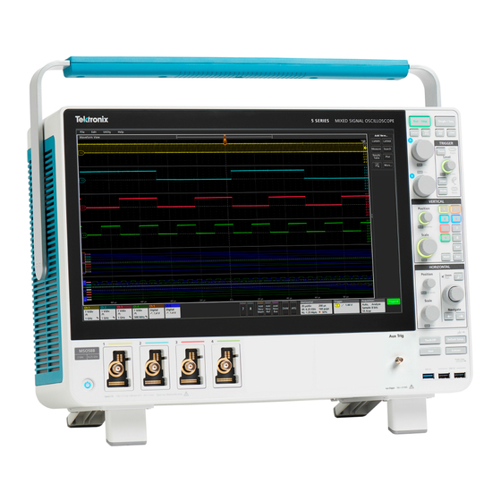
5 Series MSO
Tektronix 5 Series MSO Oscilloscope Manuals
Manuals and User Guides for Tektronix 5 Series MSO Oscilloscope. We have
1
Tektronix 5 Series MSO Oscilloscope manual available for free PDF download: Service Manual
Tektronix 5 Series MSO Service Manual (50 pages)
Brand:
Tektronix
| Category:
Server
| Size: 8 MB
Table of Contents
Table of Contents
3
List of Figures
5
List of Tables
6
Important Safety Information
7
General Safety Summary
7
Service Safety Summary
9
Terms in the Manual
9
Terms on the Product
9
Symbols on the Product
10
Preface
11
Supported Products
11
Replaceable Parts
11
Where to Find Operating Information
11
Theory of Operation
12
Power Supply
12
Figure 1: 5 Series MSO Block Diagram
12
Carrier Interface Assembly
13
Main Board and Front-End Board
13
Front Panel and Display
13
Adjustment Procedures
14
Adjustment
14
Adjustment Interval
14
Adjustment after Repair
14
Maintenance
15
Preventing ESD
15
Inspection and Cleaning
15
Exterior Cleaning (Other than Display)
15
Flat Panel Display Cleaning
16
Interior Cleaning
16
Table 1: External Inspection Checklist
16
Lubrication
17
Returning the Instrument for Service
17
Table 2: Internal Inspection Checklist
17
Removal and Replace Procedures
18
Required Equipment
18
Remove Front-Panel Knobs
18
Table 3: Required Equipment for Removal and Replacement
18
Remove SATA Riser Board Assembly
19
Remove Feet
19
Remove Handle
20
Remove Rear Grill and Case
20
Remove Rear Chassis Assembly
20
Remove the Baffle Bracket
22
Remove the Power Supply Assembly
22
Remove Carrier Interface Assembly
24
Remove the AFG Riser Assembly
26
Remove Handle Hub Assembly
27
Remove the Main Fan Assembly
27
Remove M.2 Memory Board
28
Troubleshooting 5 Series MSO
29
Service Level
30
Check for Common Problems
30
Equipment Required
30
Table 4: Failure Symptoms and Possible Causes
30
Troubleshooting Flow Chart
31
Figure 2: Primary Troubleshooting Tree
31
Troubleshoot the Power Supply
32
Figure 3: Power Status Leds
32
Instrument Self Tests
33
Software Updates
33
After Power Supply Module Replacement
34
Replaceable Parts
35
Parts Ordering Information
35
Module Servicing
35
Abbreviations
36
Using the Replaceable Parts List
36
Table 5: Parts List Column Descriptions
36
Front Cover and Rear Case
37
Figure 4: Front Cover and Rear Case Exploded View
37
Table 6: Front Cover and Rear Case
37
Carrier Interface Board and Rear Chassis
39
Figure 5: Carrier Interface Board and Rear Chassis Exploded View
39
Table 7: Carrier Interface Board and Rear Chassis
39
Baffle and Power Supply Module
42
Figure 6: Rear Chassis Baffle and Power Supply Exploded View
42
Table 8: Baffle and Power Supply Module
42
MID-Plane Chassis
44
Figure 7: MID-Plane Chassis Exploded View
44
Table 9: MID-Plane Chassis
44
Front Panel and Display
46
Figure 8: Front Panel and Display Exploded View
46
Table 10: Front Panel and Display
46
Advertisement
Advertisement
Related Products
Tektronix Phaser 550
Tektronix 545A
tektronix 575 series
Tektronix Option 5H
Tektronix 543B
Tektronix 51582-1
Tektronix 53C
Tektronix 50
Tektronix 5A13N
Tektronix 53G Series
Tektronix Categories
Test Equipment
Measuring Instruments
Amplifier
Portable Generator
Printer
More Tektronix Manuals
Login
Sign In
OR
Sign in with Facebook
Sign in with Google
Upload manual
Upload from disk
Upload from URL