Sign In
Upload
Manuals
Brands
Tektronix Manuals
Measuring Instruments
318
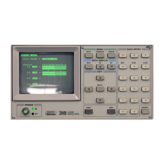
Tektronix 318 Logic Analyzer Manuals
Manuals and User Guides for Tektronix 318 Logic Analyzer. We have
1
Tektronix 318 Logic Analyzer manual available for free PDF download: Technical Manual
Tektronix 318 Technical Manual (555 pages)
LOGIC ANALYZER
Brand:
Tektronix
| Category:
Measuring Instruments
| Size: 9 MB
Table of Contents
Table of Contents
7
List of Illustrations
17
Table of Contents
20
Operator's Safety Summary
23
Service Safety Summary
25
Introduction
26
Scope
26
Description
27
Modes of Operation
27
Configurations
28
Related Documents
28
Optional Accessories
29
Options
29
Standard Accessories
29
Standard and Optional Accessories
29
318/338 Electrical Specifications
30
Specifications
30
318/338 Environmental Specifications
42
318/338 Physical Specifications
43
Options
44
Installation
45
Introduction
45
Operating Instructions
45
Power Cord
45
Power Requirements
45
Menu Characteristics
46
Menu Default Displays
46
Menu Fields and the Edit Cursor
46
Menus and Submenus
46
Power-Up Configuration Display
46
Error Message and Acquisition Status Readout
47
Inputs During Acquisition
47
Major Mode Selection Field
47
Menu Functions
47
Setup Menu
47
Threshold Menu
47
Character Menu (Serial Only) (318S1/338S1)
48
Non-Volatile (NVM) Menu (318S1/338S1)
48
OPERATING INSTRUCTIONS (Cont.)
48
Remote (RMT) Menu (318S1/338S1)
48
State Table Menu
48
Timing Diagram Menu (Parallel Only)
48
Trigger Menu
48
Diagnostics
49
Power-Up Self Test
49
Diagnostics Menu
50
User-Changeable Fields for each Test's Display
50
Diagnostics Menu: First Display
51
CRT Test
52
CRT Test: Second Display
53
Diagnostic Test Descriptions
52
KBD Test
52
CLK Test
54
WR Test
54
ACQ Test
55
SQRAM Test
55
N&DLY Test
56
SEQ Test
56
THRSH Test
57
P6107 Probe Assignment and Compensation for the 318S1 and 338S1
58
SER Test
59
RMT Test
60
NVM Test
61
Digital Logic Conventions
62
General System Description
62
Section Organization
62
Theory of Operation
62
Acquisition Module
63
P6107 External Clock Probe
63
P6451 Parallel Data Probe
63
Parallel Data Inputs (A01 and A02)
63
Acquisition Control Board (A03)
64
Clock Selector
64
Data Buffers, Delay Lines, and First Lactches
64
Event/Delay Counter
64
External Clock Circuit
64
Qualifier Selector
64
Strobe Generator
64
Threshold Circuit
64
Trigger Sequencer
64
Word Recognizer
64
Bus Buffer
65
Display Controller and Character ROM
65
Key Control Logic
65
Mainframe
65
Mother Board (A08)
65
Mpu/Display Board (A06)
65
Rams
65
Rom
65
Rom/Threshold Board (A05)
65
Threshold Circuit
65
318S1/338S1 (A07)
66
A01 Input a Board <1> <2> A02 Input B Board <3> <4
66
Detailed Circuit Descriptions for the 318
66
Left-Side Panel
66
Overview
66
Power Supply (A11And A12)
66
Serial I/O Controller
66
Serial Input Comparator
66
Address Decoder <2
67
Clock Selector <4
67
External Clock Comparator <4
67
External Clock Input <4
67
Data Threshold Buffer <4
68
Glitch Control <2> <3> <4
68
Pipeline Register <1> <3
68
Word Recognizer <1> <2> <3
68
A03 ACQ Control Board <5> <6> <7
69
Simplified Diagram of the ACQ Control Circuitry on Schematics <5> and <6>
70
Probe Compensation <4
69
I/O Address Decoder <6
71
Qualify/Sqram Data Register <5
72
Clock Qualify Flip-Flop <6
73
Qualify Logic <5> <6
73
Retiming Clock <6
73
START/STOP Logic <6
73
Strobe Generator <6
73
Trigger Qualify Flip-Flop <6
73
External or Glitch Trigger Circuit <7
74
Retiming Flip-Flop <6
74
Address Buffer <7
75
N Flag Circuit
75
THEORY of OPERATION (Cont.)
75
Trigger Sequencer Flag <7
75
Trigger Sequencer RAM <7
75
Address Decoder
76
Lsi-A A03U158 <7
76
SQRAM Data/Word Recognizer Data Multiplexer <7
76
STOP Flag Circuit
76
SUCCEED Flag Circuit
76
TRIG'D Flag Circuit
76
ACQ Status Logic
77
DL Register
77
Event/Delay Counter
77
LSI-A Input Signals
77
Mask Register
77
N Register
77
A04 ACQ Memory Board <8> <9
78
Acquisition Memory and ACQ Address Counter <8
78
Chip Select Latch
78
LSI-A Input Signals
78
LSI-A Output Signals
78
ACQ Address Counter and Carry Latch
79
Acquisition Memory
79
Address Decoder
80
Data Selector
80
Divider, Timer, and Slow Clock Detector
80
ECL-To-TTL Translator and TTL Bus Buffer
80
INTCLK Buffer
80
Oscillator
80
Timebase and MPU Bus Interface <9
80
TTL-To-ECL Translator
80
Full Valid Flag Latch
81
Lsi-B (A04U 140)
82
Internal Clock (INTCLK)
83
Simplified Diagram of the Timebase and MPU Bus Interface Circuit
84
318/338 A05 Rom/Threshold Board --<10
85
Memory Map
85
ROM Circuitry
85
Analog Switches
86
D/A Converter
86
Threshold Circuit
86
Simplified Diagram of the ROM and Threshold Circuits
87
318/338 A06 Mpu/Display Board <11
88
Bus Drivers
88
Display Controller
88
Interrupt Gates
88
Keyboard and Keyboard Controller
88
Mpu
88
Ram
88
Simplified Diagram of the Mpu/Display Board
90
318/338 A07 Serial, Non-Volatile Memory, Rs232C <17> <18
91
Chip Select Controller
91
Clock-Level Translator
91
Input Comparator
91
Non-Volatile Memory <17
91
Offset Adjust
91
Serial Input <17
91
THEORY of OPERATION (Cont.)
91
Threshold Voltage Detector
91
Battery Switch
92
Battery Voltage Checker
92
Random Access Memory
92
Baud-Rate Selector
93
Data Bus Buffer
93
I/O Selector
93
Serial Data Acquisition <18
93
External Trigger Latch and Data Polarity
94
Option I/O Device Addressing and Function
94
Serial I/O Controller
94
Baud-Rate Selector
95
Control <18
95
Level Converter
95
Programmable Bit-Rate Generator Outputs
95
RS-232 Control <18>
95
Serial I/O Controller
95
318/338 A10 CRT Board <14
96
Z-Axis Amplifier
96
Horizontal Sweep Generator
97
318/338 A11 Power Supply <15> <16
98
Line Input <15
98
Vertical Sweep Generator
98
Inverter Start Network <15
99
Dead Time Controller
100
Inverter Control <16
100
Low Voltage Rectifiers and Regulators <16
100
Over/Under Voltage Protection <16
100
Regulator
100
Volt and -12 Volt Supplies
100
Volt Supply
100
Address Decoder <20
101
Detailed Circuit Descriptions for the 338
101
Fan Circuit and Fan <16
101
Overview
101
Glitch Control (CH 0-7) <21
102
A03 ACQ Control Board <5> <6> <7
103
Simplified Diagram of the ACQ Control Circuitry on Schematics <5> and <6>
104
Probe Compensation <21> <22
103
Threshold Buffer <22
103
Word Recognizer <19> <21
103
I/O Address Decoder <6
105
Qualify/Sqram Data Register <5
106
Clock Qualify Flip-Flop <6
107
Qualify Logic <5
107
Retiming Clock <6
107
START/STOP Logic <6
107
THEORY of OPERATION (Cont.)
107
Trigger Qualify Flip-Flop <6
107
External or Glitch Trigger Circuit <7
108
Retiming Flip-Flop <6
108
Strobe Generator <6
108
Address Buffer <7
109
Trigger Sequencer Flag <7
109
Trigger Sequencer RAM <7
109
Lsi a A03U158 <7
110
N Flag Circuit
110
SQRAM, Data/Word Recognizer, Data Multiplexer <7
110
STOP Flag Circuit
110
SUCCEED Flag Circuit
110
TRIG'D Flag Circuit
110
ACQ Status Logic
111
Address Decoder
111
DL Register
111
Event/Delay Counter
111
Mask Register
111
N Register
111
LSI-A Output Signals
112
A04 ACQ Memory Board <8> <9
113
Acquisition Memory
113
Acquisition Memory and ACQ Address Counter <8
113
Chip Select Latch
113
ACQ Address Counter and Carry Latch
114
Address Decoder
114
Data Selector
114
Divider, Timer, and Slow Clock Detector
114
INTCLK Buffer
114
Oscillator
114
Timebase and MPU Bus Interface <9
114
TTL-To-ECL Translator
114
ECL-To-TTL Translator and TTL Bus Buffer
116
Full Valid Flag Latch
116
LSI-B (A04U140) Output Signals
117
Lsi-B A04U140
117
Internal Clock (INTCLK)
118
Verification and Adjustment Procedures
119
318/338 Multi-Probe Test Fixture
120
Introduction
120
Suggested Test Instruments
123
Test Setup Information
123
Equipment Needed for the Adjustment Procedures and the Performance Check Procedures
124
Functional Check Procedures for the 318
125
Minimum Specifications for Test Equipment
125
Check 1. Power-Up Diagnostics
126
Check 2. Keyboard
126
Index of Functional Checks
126
Mainframe and Parallel Analyzer
126
Check 3. CRT
127
Check 4. Threshold Voltage
128
Check 5. Parallel Data Acquisition with Test Output
130
Check 6. Glitch Data Acquisition with Test Output
137
Check 7. Serial State Analyzer Check for the 318
138
Adjustment Procedures for the 318
141
Introduction
141
Index of Adjustment Steps
142
Mainframe
142
Adjustable Power Supply Tolerances
143
Non-Adjustable Power Supply Tolerances
144
Parallel Analyzer
146
Clock Delay with Extender
156
Clock Delay Without Extender
156
Serial State Analyzer
158
Index of Performance Checks
162
Performance Check for the 318
162
Test 1. Threshold Voltages
162
The Performance Checks
162
Voltage Levels for Testing TTL
165
Voltage Levels for Testing V1, V2, and V3
165
Test 2. Parallel Data Acquisition Word Recognition and Trigger Sequencer Check with External Clock Minimum Period
166
Test 3. Glitch Data Acquisition and Glitch Trigger
174
Positive Glitch Pulse Generator Setup
176
Negative Glitch Pulse Generator Setup
177
Test 4. Start Output and Trigger Output Test
177
Test 5. External Trigger Input Test
178
Test 6. Serial State Analyzer (318S1)
179
Functional Check Procedures for the 318
183
Index of Functional Checks
183
Check 1. Power-Up Diagnostics
184
Check 2. Keyboard
184
Check 3. Crt
184
Mainframe and Parallel Analyzer
184
Check 4. Threshold Voltage
186
Check 5. Parallel Analyzer Check with Test Output
187
Check 6. Glitch Data Acquisition Using Test Output
194
Check 7. Serial State Analyzer Check for the 338S1
195
Adjustment Procedures for the 338
197
Introduction
197
Index of Adjustment Steps
198
Adjust Power Supplies
199
Mainframe
199
Non-Adjustable Power Supply Tolerances
200
Adjust CRT Circuit
201
Adjust Threshold Voltages on the A05 ROM Board
202
Adjust Threshold Voltages on the A02 Input-B Board
204
Parallel Analyzer
204
Data Threshold DC Balance
206
Probe Compensation for the P6107 External Clock Probe
206
Adjust Ext Clk↑ and Ext Clk↓ Delay
207
Adjust Delay of RET CLK, WE, ADRS CLK and TRIG CLK
209
Clock Delay with Extender
212
Adjust Threshold Voltages on the A07 Board
213
Clock Delay Without Extender
213
Serial State Analyzer
213
Adjust Input Capacitance and Serial Data Probe Compensation
215
Adjust Non-Volatile Memory Battery Backup Threshold
218
Index of Performance Checks
218
Performance Check for the 338
218
Setup
219
Test 1 - Threshold Voltages
219
Threshold Level TTL
221
Threshold Levels V1, V2, and V3
221
Voltage Levels for Testing TTL
221
Test 2 - Parallel Data Acquisition, Word Recognition, and Trigger Sequencer Checks with External Clock Minimum Period
222
Parallel Data Test Oscilloscope Setup
225
Test Conditions and Expectations
227
Test 3 - Glitch Data Acquisition and Glitch Trigger
231
Setup
232
Positive Glitch Pulse Generator Setup
233
Negative Glitch
234
Negative Glitch Pulse Generator Setup
234
Test 4 - Start Output and Trigger Output
234
Test 5 - External Trigger Input
236
Test 6 - Serial State Analyzer (338S1)
237
Serial State Analyzer Test Setup
239
Maintenance Precautions
240
Maintenance: General Information
240
Soldering
240
Test Equipment Required for Maintenance
240
Tools Required for Maintenance
240
Troubleshooting Trees
240
Light-Emitting Diodes (Leds)
241
Static Precautions
241
Exterior Cleaning
242
Lithium Battery Replacement
242
Preventive Maintenance
242
Relative Susceptibility of Semiconductors to Static Discharge Damage
242
Cleaning Guidelines
243
Inspection
243
Interior Cleaning
243
Acquisition Boards and Probes
244
Corrective Maintenance
244
Obtaining Replacements
244
Repairing Multi-Conductor Connectors
244
Circuit Board Pin Replacement
245
Circuit Board Locations
246
Component Locations
246
Disassembly/Installation Procedures
246
General Disassembly Precautions
246
Circuit Board Locations
247
Removing the Cabinet
248
Removing the Front Panel
248
Removing the Keyboard
249
Removing the Power Supply Circuit Boards
249
Power Supply Removal
250
Removing the Cathode-Ray Tube (CRT)
251
Removing the CRT Circuit Board
251
Diagnostic Test Common Signal Paths
254
Diagnostic Test Descriptions
254
Index of 318 Diagnostic Test Descriptions
254
Maintenance: Troubleshooting
254
Diagnostic Test Common Signal Paths
255
Keyboard Test
256
Keyboard Test Key Code and Interrupt Assignment
256
Mainframe
256
CRT Adjustment
257
CRT Test
257
CRT Calibration and Check
258
Jump Table ROM Test
259
Display RAM Test
260
System RAM Test
261
ROM Test
262
ROM Test Address Assignment
262
A03 and A04 Partial ACQ Address Assignment
263
Clock Test
264
Parallel Analyzer
264
Clock Test Program Ranges
265
Word Recognizer Test
266
Word Recognizer Test Port Addresses
267
Word Recognizer Test
269
ACQ Test Port Addresses
270
Acquisition RAM Test
270
ACQ Memory Test
272
Sequence RAM Test
273
SQRAM Test Port Addresses
274
SQRAM Test SQRAM Data Connections
274
SQRAM Test
275
N & Delay Test
276
N and Delay Counter Test
278
Threshold Test
279
Threshold Test Data Values
280
SEQ Test
281
318S1 Serial Analysis/Rs232C/Nvm
282
Battery Test
282
Non-Volatile Memory Test
283
Serial Test
285
Option I/O Function List
286
Serial Test I/O Addresses
286
Serial Test Baud Select Bits
287
Diagnostic Test Failure Codes
289
Diagnostic Test Failure Codes
290
Troubleshooting Trees
292
Troubleshooting Tree 2: Startup Self Test
293
Troubleshooting Tree 3: Power Supplies A11, A12
294
Troubleshooting Tree 4: CRT A10
296
Troubleshooting Tree 5: MPU A06
300
Troubleshooting Tree 6: Clock A04
305
Troubleshooting Tree 7: Word Recognizer (WR A01 A02)
307
Troubleshooting Tree 8: Data Acquisition (ACQ A01 A02)
310
Troubleshooting Tree 9: SQRAM A03
316
Troubleshooting Tree 10: N&DL A03
320
Troubleshooting Tree 11: SEQ A03
322
Troubleshooting Tree 12: T/H A01, A02
326
Troubleshooting Tree 13: T/H A04
327
Troubleshooting Tree 14: SER A07 (TSTSR2)
328
Troubleshooting Tree 15: RMT A07 (TSTRM2)
332
Troubleshooting Tree 16: Non-Volatile Memory (NVM A07)
336
Troubleshooting Tree 17: Can't Get Glitch
338
Troubleshooting Tree 18: Can't Get Good Data
339
Troubleshooting Tree 19: Diagnostics Pass Can't Stop
341
Troubleshooting Tree 20: Can't Get Glitch Trigger
343
Troubleshooting Trees
344
Troubleshooting Tree 21: Test Output - Doesn't Work
345
Diagnostic Test Descriptions
346
Diagnostic Test Common Signal Paths
347
Keyboard Test Key Code and Interrupt Assignment
348
CRT Adjustment
349
CRT Calibration and Check
350
Jump Table ROM Test
351
Display RAM Test
352
System RAM Test
353
MPU Memory Address Assignment
354
A03 and A04 Partial ACQ Address Assignment
356
Parallel Analyzer
357
ROM Test Address Assignment
354
Clock Test
358
Clock Test Program Ranges
359
Word Recognizer Test
359
Word Recognizer Test Port Addresses
360
Word Recognizer Test
362
Acq Ram Test
363
ACQ Test Port Addresses
364
ACQ Memory Test
365
SQRAM Test Port Addresses
366
SQRAM Test
367
SQRAM Test SQRAM Address Connections
368
SQRAM Test SQRAM Data Connections
368
N & DELAY Test
369
N and Delay Counter Test
371
Threshold Test
372
Threshold Test Data Values
373
SEQ Test
374
S1 Serial Analysis/Rs232C/Nvm
375
RS-232 Test
376
Serial Test I/O Addresses
379
Option I/O Function List
379
Serial Test Baud Select Bits
380
Troubleshooting Tree 1: Power on
385
Troubleshooting Trees
386
Troubleshooting Tree 3: Power Supplies A11, A12
388
Troubleshooting Tree 4: CRT A10
390
Troubleshooting Tree 5: MPU A06
394
Troubleshooting Tree 6: Clock A04 (CLK)
399
Troubleshooting Tree 7: Word Recognizer (WR A01 A02)
401
Troubleshooting Tree 8: Data Acquisition (ACQ A01 A02)
405
Troubleshooting Tree 9: SQRAM A03
412
Troubleshooting Tree 10: NDL A03
416
Troubleshooting Tree 11: SEQ A03
418
Troubleshooting Tree 14: SER A07 TSTSR2
424
Troubleshooting Tree 15: REMOTE A07 TSTRM2 (RMT)
428
Troubleshooting Tree 16: Non-Volatile Memory (NVM A07)
432
Troubleshooting Tree 18: Can't Get Good Data
435
Troubleshooting Tree 19: Diagnostics Pass Can't Stop
436
Troubleshooting Tree 20: Can't Get Glitch Trigger
437
Troubleshooting Tree 21: Test Output Doesn't Work
438
Appendix A REFERENCES
499
Appendix C ERROR and ACQUISITION STATUS MESSAGES
503
Appendix E ERROR CODES
511
Error Codes in Self Test
511
Error Codes of Parallel Tests in Diagnostics Menu
512
Error Codes of Serial Tests in Diagnostics Menu
513
Error Codes of Remote Tests in Diagnostics Menu
514
Error Codes of NVM Tests in Diagnostics Menu
515
Advertisement
Advertisement
Related Products
Tektronix 338
Tektronix 308
Tektronix KEITHLEY 3765
Tektronix 3177
Tektronix 3B2 TIME-BASE
Tektronix 3L5
Tektronix 3A72
Tektronix 314
Tektronix 315D Series
Tektronix 310A
Tektronix Categories
Test Equipment
Measuring Instruments
Amplifier
Portable Generator
Printer
More Tektronix Manuals
Login
Sign In
OR
Sign in with Facebook
Sign in with Google
Upload manual
Upload from disk
Upload from URL