Sign In
Upload
Manuals
Brands
Tektronix Manuals
Test Equipment
2336YA
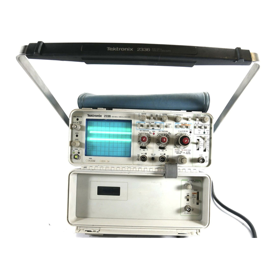
Tektronix 2336YA Manuals
Manuals and User Guides for Tektronix 2336YA. We have
1
Tektronix 2336YA manual available for free PDF download: Instruction Manual
Tektronix 2336YA Instruction Manual (308 pages)
Brand:
Tektronix
| Category:
Test Equipment
| Size: 23.1 MB
Table of Contents
Table of Contents
3
List of Illustrations
5
List of Tables
7
Operators Safety Summary
8
Servicing Safety Summary
9
Section 1 Specification
11
Introduction
11
Accessories
11
Available Option
11
Performance Conditions
11
Environmental Characteristics
11
Electrical Characteristics
12
Physical Characteristics
21
Option Electrical Characteristics
21
Section 2 Operating Instructions
23
Preparation for Use
23
Safety Considerations
23
Line Voltage Selection
23
Controls. Connectors
23
Line Voltage and Fuse Selection
23
Option 03 Line Voltage and Fuse Selection
23
Power Cord
24
And Indicators
25
Power and Display
25
Vertical
25
Power and Display Controls and Indicators
25
Horizontal
27
Atrigger
28
A TRIGGER Controls. Connector. and Indicator
28
Btrigger
29
Rear Panel
30
B TRIGGER Controls. Connector. and LCD Readout
30
Operating Considerations
31
Graticule
31
Rear-Panel Connectors
31
Graticule Measurement Markings
31
Grounding
32
Signal Connections
32
Input Coupling Capacitor Precharging
32
Instrument Cooling
32
Line Fuse
33
Oscilloscope Displays
33
Introduction
33
Normal Sweep Display
33
Signal Display
33
Magnified-Sweep Display
34
Delayed-Sweep Display
34
Delayed-Sweepmeasurements
34
Single-Sweep Display
34
X-Y Display
35
Introduction
37
General Description
38
Detailed Circuit Description
42
Channel 1 a N D Channel 2
42
Attenuators
42
Vertical Preamplifiers
42
Diode Gates. and Delay Line Driver
43
Vertical Preamplifier. Diode Gate. and Delay Line Driver. Simplified Block Diagram
44
Vertical Output Amplifier
46
Vertical Switching Logic and Chop Blanking
47
Trigger
49
Trigger Circuitry. Detailed Block Diagram
50
Trigger Signal Slow Path (Low Frequency)
51
Trigger Signal Fast Path (High Frequency)
52
Sweep
55
Sweep Operation in the B Sweep Mode
61
A a N D Btlmlng SWITCHES
62
Horizontal Amplifier
62
3-13. Horizontal Amplifier, Detailed Block Diagram
63
Crt Circuit
65
Low-Voltage Power Supply
69
3-16. Foldover Circuit Action
70
Fan Circuit
71
Calibrator
71
Delta Time
72
3-18. Simplified Diagram of the Delay Time Switching and Prescaling Circuit
74
3-19. Exclusive-OR Gate Switching Action
77
Performance Check Interval
79
Limits and Tolerances
79
Special Fixtures
79
Preparation
79
Test Equipment Required
80
Index to Performance Check Steps
82
Introduction
79
Test Equipment Required
79
Vertical
83
DC Accuracy Limits
85
Low-Frequency Compensation Setup
86
Triggering
91
Switch Combinations for a Trigger Checks
91
Switch Combinations for B Trigger Checks
92
Test Setup for External Trigger and Jitter Checks
93
Horizontal
96
Settings for Timing Accuracy Checks
97
A Time Readout Accuracy
98
External Z-Axis and Calibrator
101
Section 5 Adjustment Procedure
103
Introduction
103
Test Equipment Required
103
Limits and Tolerances
103
Partial Procedures
103
Internal Adjustments and Adjustment Interaction
104
Preparation for Adjustment
104
Adjustment Interactions
105
Index to Adjustment Procedure
106
Main Power Supply
107
Main Power Supply Tolerances and P-P Ripple
108
Display and Z.axis
109
Vertical
111
Vertical DC Accuracy Checks
115
Triggering
121
Switch Combinations for B Trigger Checks
123
Horizontal
128
A Time Linearity
130
Settings for Timing Accuracy Checks
132
A Time Readout Accuracy
133
A Trigger Holdoff Time
136
External Z-Axis and Calibrator
137
Section 6 Maintenance
139
Static-Sensitive Components
139
Relative Susceptibility to Static-Discharge Damage
139
Preventive Maintenance
140
Introduction
140
General Care
140
Inspection and Cleaning
140
Lubrication
143
Semiconductor Checks
143
Periodic Readjustment
143
Troubleshooting
143
Introduction
143
Troubleshooting Aids
143
Troubleshooting Equipment
145
Troubleshooting Techniques
145
6-1. Multipin Connector Orientation
145
Suggested Troubleshooting Equipment
146
Attenuator Contact Pressure Check
149
Attenuator Contact Alignment
149
Corrective Maintenance
150
Introduction
150
Maintenance Precautions
150
Obtaining Replacement Parts
150
Maintenance Aids
150
Interconnections
150
Maintenance Aids
151
Transistors and Integrated Circuits
152
Soldering Techniques
152
Removal and Replacement Instructions
153
Cabinet
154
Lid Cover
154
A30-Delta Time Logic Circuit Board
154
B Trigger Panel
155
Delta Time Interconnect Cable
155
Cathode-Ray Tube
156
A1 5-Vert 0Utih.V. Power
157
Supply Circuit Board
158
A1 I-Negative Regulator Circuit Board
160
A1 2-Positive Regulator Circuit Board
160
A23-Trigger Circuit Board
160
A24-Sweepihoriz Amp/Opt Circuit Board
161
Timing Switch Assembly
161
Attenuators
165
6-5. Vertical Attenuator Exploded View
166
Repackaging for Shipment
169
Selectable Components
169
Section 7 Options
171
Introduction
171
Option03
171
Section 10 Replaceable Mechanical Parts
281
Change Information
299
Advertisement
Advertisement
Related Products
Tektronix 2337
Tektronix 2335
Tektronix Keithley 2302
Tektronix Keithley 2302-PJ
Tektronix Keithley 2306
Tektronix Keithley 2306-PJ
Tektronix Keithley 2306-VS
Tektronix Keithley 2380-500-30
Tektronix Keithley 2380J-500-30
Tektronix 2221A
Tektronix Categories
Test Equipment
Measuring Instruments
Amplifier
Printer
Portable Generator
More Tektronix Manuals
Login
Sign In
OR
Sign in with Facebook
Sign in with Google
Upload manual
Upload from disk
Upload from URL