Sign In
Upload
Manuals
Brands
Tektronix Manuals
Monitor
1760 series
Tektronix 1760 series Manuals
Manuals and User Guides for Tektronix 1760 series. We have
3
Tektronix 1760 series manuals available for free PDF download: User Manual, Service Manual
Tektronix
1740A series
User Manual
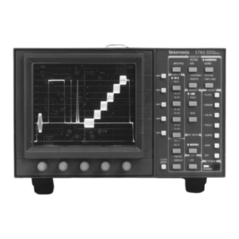
Tektronix 1760 series User Manual (368 pages)
Waveform/Vector Monitor
Brand:
Tektronix
| Category:
Measuring Instruments
| Size: 5 MB
Table of Contents
Service Manual
2
Standards Compliance
7
Specifications
8
Theory of Operation
8
Table of Contents
9
List of Figures
12
Figure 2-6: 1700F05 Rack Mounting with a 1700F07 Utility Drawer
13
List of Tables
14
Power Source
16
Safety Summary
16
Specification
19
Characteristics Tables
22
Table 1-1: Waveform Vertical Deflection
23
Table 1-2: External Reference
25
Table 1-3: Waveform Horizontal Deflection
26
Table 1-4: Measurement Cursors
27
Table 1-6: Calibrator
27
Table 1-7: Vector Mode
28
Table 1-8: Audio Mode
29
Table 1-9: Time Code
30
Table 1-10: SCH Phase Mode(1750-Series and 1760 OPT SC Only)
30
Table 1-11: Component Vector Mode (1760-Series Only)
31
Table 1-12: Lightning Mode (1760-Series Only)
31
Table 1-13: Bowtie Mode (1760-Series Only)
31
Table 1-14: Transcoded GBR Outputs
32
Table 1-15: CRT Display
32
Table 1-16: Power Source
33
Table 1-17: Environmental Characteristics
33
Table 1-18: Certification
33
Table 1-19: Physical Characteristics
34
Installation
36
Figure 2-1: Dimensions of the 1700F00 Plain Cabinet
37
Mechanical Installation
37
Figure 2-2: 1700F02 Portable Cabinet
38
Figure 2-3: Rear View Showing the Securing Screws
39
Figure 2-4: the 1700F05 Side-By-Side Rack Adapter
40
Figure 2-5: A1700F05 with a Blank Front Panel (1700F06)
40
Electrical Installation
42
Figure 2-7: Custom Installation of an Instrument
42
Rear Panel Connectors
43
Table 2-1: Power Cord Options
43
Figure 2-8: Rear Panel Connectors
44
Figure 2-9: Rear Panel REMOTE Connector
45
Remote Connector Converter
47
Figure 2-10: Replacement Adapter for 1740/1750
47
Figure 2-11: Rear Panel RS232 Connector
48
Procedure for Loading Software
50
Figure 2-12: Hookup for 9-Pin PC Connector
50
Figure 2-13: Alternate Hookup for 9-Pin PC Connector
50
Figure 2-14: RS232 Cable Standard and Alternate Hookups for 25-Pin PC Connector
51
Calibration of New Features
54
Operating Instructions
56
Operating Instructions
57
Figure 2-16: 1760 Front Panel
57
General Menu Information
58
Figure 2-17: the CRT Menu, with the Bezel Controls and Buttons
58
Functional Overview
59
Table 2-3: the Available Display Modes
60
Displaying a Signal
62
Block Diagram Description
65
Block Diagram 2 Vector – SCH – Component
68
Block Diagram 3 Microprocessor and Line Rate Controller
70
Circuit Theory
73
Diagram 10 Remote & 1760–Series / XROM Bus Connectors
81
Diagram 13 DACS & Digital Control
83
Diagram 18 Reference SCH
90
Figure 3-1: NTSC Line Count (U24) & Color Frame 1 SCH Field Pulse
92
Figure 3-2: PAL Line Count (U24) & Color Frame 1 SCH Field Pulse
92
Diagram 19 Component Inputs, Transcoders, & RGB Outputs
93
Table 3-1: Transcoder Signal Mixing
93
Diagram 20 Component Control and Switching
94
Table 3-2: Component Display Output Switching
95
Diagram 21 Low Voltage Power Supply
96
Diagram 22 High Voltage Power Supply
99
Diagram 23 XROM
101
Performance Verification
104
Recommended Equipment List
104
Figure 4-1: External Horizontal or RGB/YRGB Cable Adapter
108
Figure 4-2: Remote Sync Cable Adapter
108
Figure 4-3: Audio and Timecode Cable Adapter
109
Performance Check Procedure Short-Form Reference
110
Table 4-1: Short-Form Performance Check
110
Performance Check Procedure
113
Figure 4-4: Timing Cursor Check
120
Table 4-2: Vector Cursor Readout Values
121
Figure 4-5: Fast DC Restorer Response
128
Figure 4-6: R-Y Display
131
Table 4-3: Audio and Timecode Values
136
Figure 4-7: Audio Display
137
Figure 4-8: Option Blanking Pulse
142
Figure 4-9: Bowtie Common Mode Rejection Ratio
143
Adjustment Procedures
147
Adjustment Procedure
147
Recommended Equipment List
147
Figure 5-1: External Horizontal/Rgb and YRGB Cable Adapter
151
Figure 5-2: Remote Sync Cable Adapter
151
Figure 5-3: Audio and Timecode Cable Adapter
152
Figure 5-4: RS232 Cable Standard and Alternate Hookups for 9-Pin PC Connector
153
Figure 5-5: RS232 Cable Standard and Alternate Hookups for 25-Pin
154
Getting Started
155
Functional Description of PC Display
157
Circuit Board Adjustment Locations
159
Waveform Illustrations
162
Maintenance
168
Service Options
168
Tektronix Service
168
Preventive Maintenance
168
Cleaning
168
Replacing and Cleaning the Air Filter
169
Visual Inspection
169
Static-Sensitive Components
170
Table 6-1: Static Susceptibility
170
Determining the Software Version
171
Performance Checks and Readjustments
171
General Troubleshooting Techniques
171
Line Fuse Replacement
173
Specific Troubleshooting Techniques
173
Power Supply
173
Troubleshooting Procedure
173
Introduction
173
Low Volts Supply
174
Table 6-2: Power Supply Fault Symptoms
174
Table 6-3: Low Volts Supply Voltages
174
Table 6-4: Control Circuit Test Points
176
Table 6-5: Shut down Logic Levels
177
High Volts Supply
178
Table 6-6: High Volts Supply Fault Symptoms
178
Table 6-7: High Voltage Oscillator Test Points
179
Corrective Maintenance
180
Tektronix Service Offerings
180
Table 6-8: 1740A/1750A/1760-Series Replacement Circuit Boards
181
Factory Replacement Parts
182
Etched Circuit Boards
183
Major Assembly Interconnection
185
Mechanical Disassembly/Assembly
186
Graticule Light Removal and Replacement
187
Connector
189
CRT Removal
189
Replacement of the CRT
190
Removing the Rear Panel and the Input and BNC Circuit Boards
191
Removing the Front Panel and the Front Panel Circuit Board
193
Removing the Main Board
194
Removing the Power Supply Board
196
Removing the Vector Board
197
Removing the Component Board (1760–Series Only)
199
Repackaging
200
Options
203
CRT Options
205
Carrying Case (1700F02)
206
Blank Panel (1700F06)
207
Utility Drawer (1700F07)
208
Index
210
Glossary
301
Advertisement
Tektronix 1760 series Service Manual (350 pages)
Waveform/Vector Monitors
Brand:
Tektronix
| Category:
Monitor
| Size: 5 MB
Table of Contents
Table of Contents
6
Table 1- 1: Waveform Vertical Deflection
21
Table 1- 2: External Reference
24
Table 1- 3: Waveform Horizontal Deflection
24
Table 1- 4: Measurement Cursors
25
Table 1- 6: Calibrator
26
Table 1- 7: Vector Mode
26
Table 1- 8: Audio Mode
27
Table 1- 9: Time Code
28
Table 1- 10: SCH Phase Mode (1750 Series and 1760 Option SC Only)
28
Table 1- 11: Component Vector Mode (1760 Series Only)
30
Table 1- 12: Lightning Mode (1760 Series Only)
30
Table 1- 13: Bowtie Mode (1760 Series Only)
31
Table 1- 14: Transcoded GBR Outputs
31
Table 1- 15: CRT Display
32
Table 1- 16: Power Source
32
Table 1- 17: Environmental Characteristics
32
Table 1- 18: Physical Characteristics
33
Table 1- 19: Certifications and Compliances
34
Figure 2- 1: Dimensions of the 1700F00 Plain Cabinet
38
Figure 2- 2: 1700F02 Portable Cabinet
39
Figure 2- 3: Rear View Showing the Securing Screws
40
Figure 2- 4: the WFM7F05 Side-By-Side Rack Adapter
41
Figure 2- 5: a WFM7F05 with a Blank Front Panel (1700F06)
41
Figure 2- 6: WFM7F05 Rack Mount Cabinet with a 1700F07 Utility Drawer
42
Figure 2- 7: Custom Installation of an Instrument
43
Figure 2- 8: Rear Panel Connectors
45
Figure 2- 9: Rear Panel REMOTE Connector
46
Table 2- -1: Remote Connector
48
Figure 2- 11: Rear Panel RS232 Connector
49
Figure 2- -12: Standard and Alternate Hookups for the 9-Pin
52
Figure 2- 13: Standard and Alternate Hookups for 25-Pin PC Connector
53
Figure 2- 14: 1760 Front Panel
58
Table 2- 2: the Available Display Modes
61
Diagram <11> Z-Axis & Control
81
Diagram <12> Front Panel
82
Diagram <13> Dacs & Digital Control
82
Diagram <14> Subcarrier Regenerator
83
Diagram <15> Phase Shifter
85
Diagram <16> Demodulator
86
Diagram <17> Internal SCH
87
Diagram <18> Reference SCH
90
Diagram <19> Component Inputs, Transcoders, & RGB Outputs
92
Table 3- 1: Transcoder Signal Mixing
93
Diagram <20> Component Control and Switching (1760 Series Only)
94
Table 3- 2: Component Display Output Switching
94
Diagram <21> Low Voltage Power Supply
96
Diagram <22> High Volts Power Supply
99
Figure 3- 3: Pinout of the CRT Socket
100
Performance Verification
101
Recommended Equipment List
101
Figure 4- 1: External Horizontal or RGB/YRGB Cable Adapter
104
Figure 4- 2: Remote Sync Cable Adapter
105
Figure 4- 3: Audio and Timecode Cable Adapter
105
Performance Check Procedure Short-Form Reference
106
Table 4- 1: Short-Form Performance Check
106
Performance Check Procedure
109
Figure 4- 4: Timing Cursor Check
116
Table 4- 2: Vector Cursor Readout Values
117
Figure 4- 5: Fast DC Restorer Response
124
Figure 4- 6: R- y Display
127
Table 4- 3: Audio and Timecode Values
132
Figure 4- 7: Audio Display
133
Figure 4- 8: Option Blanking Pulse
136
Figure 4- 9: Bowtie Common Mode Rejection Ratio
138
Adjustments
141
Required Equipment
141
Figure 5- 1: External Horizontal/Rgb and YRGB Cable Adapter
145
Figure 5- 2: Remote Sync Cable Adapter
145
Figure 5- 3: Audio and Timecode Cable Adapter
146
Initial Setup
149
Functional Description of PC Display
150
Circuit Board Adjustment Locations
152
Waveform Illustrations
155
Maintenance
159
Preventing ESD
159
Preventive Maintenance
159
Performance Checks and Adjustments
160
Inspection and Cleaning
160
Table 6- 1: External Inspection Check List
161
Replacing the Line Fuse
163
Troubleshooting
163
Table 6- 2: Power Supply Fault Symptoms
164
Table 6- 3: Low Volts Supply Voltages
164
Table 6- 4: Control Circuit Test Points
166
Table 6- 5: Shut down Logic Levels
167
Corrective Maintenance
170
Circuit Boards
170
Mechanical Disassembly/Assembly
171
Removing the Bezel
171
Replacing the Graticule Light
172
Removing the CRT
174
Removing the Rear Panel
177
Removing the Front Panel and the Front Panel Circuit Board
179
Removing the Main Board
180
Removing the Power Supply Board
182
Removing the Vector Board
183
Removing the SCH Board
184
Removing the Component Board
184
(1760 Series Only)
184
Repackaging
185
Connector
274
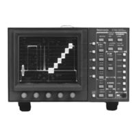
Tektronix 1760 series User Manual (180 pages)
1760 Series Component Waveform / Vector Monitor
Brand:
Tektronix
| Category:
Monitor
| Size: 2 MB
Table of Contents
User Manual
1
Warranty
3
General Safety Summary
5
To Avoid Fire or Personal Injury
5
Safety Terms and Symbols
6
Table of Contents
9
List of Figures
13
Service Manual
16
Contacting Tektronix
18
Introduction
19
Product Description
21
Description of Features
22
More Information
23
Options
25
Option SC
25
Power Cord Options
25
CRT Options
26
Accessories
27
Standard Accessories
27
Optional Accessories
27
Field Upgrade Kits
28
Installation
29
Packaging for Shipment
29
Electrical Installation
30
Power Source
30
Mains Frequency and Voltage Range
31
Operational Changes
31
Remote Connector
31
RS232 Connector
31
Mechanical Installation
32
Cabinets
32
Custom Installation
32
Rackmounting
33
Instrument Configuration
35
Getting Started
37
At a Glance
39
Front-Panel Controls
39
Instrument Reset
39
Figure 2-1 Multi-Use Bezel Controls and Buttons
40
Figure 2-2 1760 Front Panel
41
Rear-Panel Connectors
46
Multi-Pin Connectors
46
Fan Filter
47
Figure 2-3 1760- - Series Rear Panel
48
Operator's Checkout Procedure
49
Required Equipment
49
Initial Equipment Connections
50
Figure 2-4 Equipment Hook-Up for Operator's Checkout
50
Procedure
51
Figure 2-5 Component Waveform Display (A123)
52
Figure 2-6 Calibrator Display
53
Figure 2-7 Two-Line LUM Filter Display of Color Bar Signal
56
Figure 2-8. Two-Line CHROM Filter Display of Color Bar Signal
57
Figure 2-9. Two-Line DIFF Filter Display of 5-Step Staircase Signal
58
Figure 2-11 Two-Field SCH R- - y Display (NTSC), Showing Proper SCH Phase
59
Figure 2-12 Two-Field SCH R- - y Display (PAL), Showing Proper SCH Phase
59
Figure 2-13 Line Select Display with 15H Selected, in 2 FIELD Sweep
60
Figure 2-14 Vectorscope Color Bar Display
61
Figure 2-15 Picture Mode Display of Color Bar Signal
62
Figure 2-16 Audio Display with Phase Error
62
Figure 2-17. NTSC SCH Display with Internal Reference Selected
63
Figure 2-18 PAL SCH Display
64
Figure 2-19 Lightning Display in MII Format
65
Figure 2-20. Diamond Display, Showing Signal Within Gamut Limit
65
Figure 2-21 Bowtie Display
66
Operation Basics
67
Functional Overview
69
Display Modes
69
Vector
69
Audio
70
SCH (Option SC Only)
70
Waveform
70
Diamond
71
Lightning
71
Bowtie
72
Multiple
72
Picture
72
Time Code
72
Displaying a Signal
73
A123 / B123
73
Inputs
73
Parade
73
Overlay
74
Sweep
74
Using the Menus
75
General Menu Information
75
Moving between Menus
75
Multi-Use Bezel Controls and Buttons
75
Clear Menu
76
Exiting a Menu Function
76
Figure 3-1. the CRT Menu, Showing Bezel Controls and Bezel Buttons
76
Filter Menu
77
Cursor Menu
78
Figure 3-2 the VECTOR CURSOR Menu
78
Waveform Cursor Control
79
Figure 3-3 the WAVEFORM CURSOR Menu
80
Vector + Waveform (Multiple)
81
Using the Cursors
81
Line Select Menu
84
Preset Menu
86
Configure Menu
88
Input
88
Format
89
Vector
89
Standard
90
Offset
91
Calibrate
92
REFERENCE (1765 Only)
93
Remote
93
Gain Menu
94
CRT Menu
95
Remote Operation
97
Using Presets through the Remote
97
Making Measurements
99
Basic Measurements
101
Waveform Graticule
101
Horizontal Scale
101
Figure 4-1 NTSC Waveform/Vector Graticule
102
NTSC Vertical Scales
102
Dual-Standard Vertical Scale
103
Figure 4-2 PAL Waveform/Vector Graticule
103
PAL Vertical Scale
103
Figure 4-3 Dual Standard Waveform/Vector Graticule
104
Making Waveform Measurements
105
Horizontal Sync Amplitude
105
K-Factor Measurements
105
Peak White
105
Vector Graticule
106
Figure 4-4 Vector Targets
107
Making Vector Measurements
109
Chroma Bandwidth
109
Differential Phase and Gain
109
Figure 4-5 Differential Gain and Phase Measurements
109
Making SCH Phase Measurements
110
Ntsc
110
Figure 4-6 NTSC Dual-Dot SCH Display
111
Figure 4-7 NTSC Single-Dot SCH Display
111
Figure 4-8 PAL SCH Display
112
Pal
112
Sch R
112
Figure 4-10 Two-Field SCH R- - y Display (NTSC), Showing Proper SC/H Phase
113
Figure 4-9 Two-Line SCH R- - y Display (NTSC), with Proper SC/H Phase
113
Figure 4-11 Two-Field SCH R- - y Display (NTSC), Showing Approximate 10° Phase Error
114
Figure 4-12 Two-Field SC/H R- - y Display (PAL), Showing Proper SC/H Phase
114
Making Audio Measurements
115
Figure 4-13 Audio Displays
115
Lightning Measurements
116
Figure 4-14 Lightning Display Showing Correct Timing
116
Figure 4-15 Lightning Display Showing Delay
118
Using the Diamond Display
119
Figure 4-16. Diamond Display Showing Signal Inside Gamut Limits
119
Using the Bowtie Display
121
Figure 4-17 Bowtie Display Showing a Sharp Null
121
Time Code Display
123
Figure4-3 Dualstandard Waveform/Vector Grati Cule 4-4
107
Figure4-12 Two-Fieldsc/H R--Y Display(Pal),Showing
115
Calibration
125
Adjusting Instrument Gain
125
Appendices
127
Appendix A
129
Appendix A Performance Specifications
129
Reference Information
129
Reliability
129
Electrical Specifications
130
Certifications and Compliances
143
Appendix B Remote Connectors
147
Figure B-1 Rear Panel REMOTE Connector
147
Figure B-2 Using the 1760- - Series as a 1740 / 1750- - Series Replacement
150
Remote Connector Converter
150
Figure B-3 Rear Panel RS232 Connector
151
Figureb-2 Usingthe1760--Seriesasa1740/1750--Series
151
Appendix C User Service
153
Cleaning or Replacing the Fan Filter
153
Fuse Replacement
153
Graticule Light Replacement
154
Figure C-1 Graticule Light Replacement
155
Cleaning
156
Replacing the CRT Filter
157
Appendix D Software Version
159
Advertisement
Advertisement
Related Products
Tektronix 1761
Tektronix 1765
Tektronix 1740A/1750A
Tektronix 1705A
Tektronix 1750A Series
Tektronix 1751A
Tektronix 1755A
Tektronix 1750 Series
Tektronix 1751
Tektronix 1735 HD
Tektronix Categories
Test Equipment
Measuring Instruments
Amplifier
Portable Generator
Printer
More Tektronix Manuals
Login
Sign In
OR
Sign in with Facebook
Sign in with Google
Upload manual
Upload from disk
Upload from URL