Sign In
Upload
Manuals
Brands
Tektronix Manuals
Test Equipment
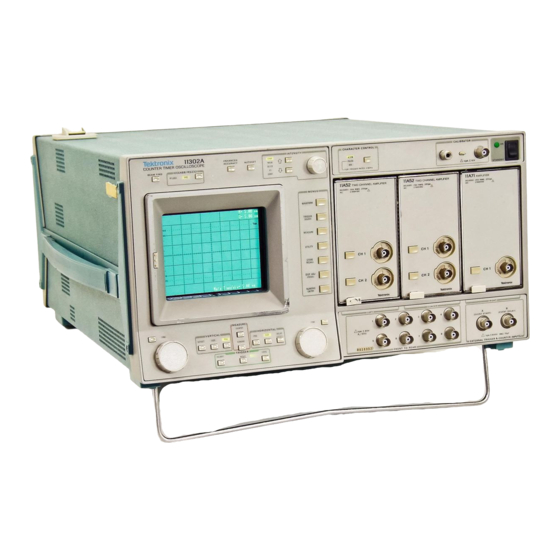
11302A
Tektronix 11302A Manuals
Manuals and User Guides for Tektronix 11302A. We have
2
Tektronix 11302A manuals available for free PDF download: User's Reference Manual, Service Reference Manual
Tektronix 11302A User's Reference Manual (499 pages)
Counter Timer Oscilloscope
Brand:
Tektronix
| Category:
Test Equipment
| Size: 73 MB
Table of Contents
Key to Manuals
3
How to Use this Manual
4
Table of Contents
6
Contents
9
Illustrations
14
Operators Safety Summary
20
Introduction
22
Oscilloscope System Architecture
23
Measured Signals
23
Triggering
25
Counter View Display
25
Measurement Interval
26
Display Paths
26
Installation
29
Bench Model
29
Operating Power Information
30
Power-Cord and Plug Identification
32
Operating Environment
33
External Interface Connection
36
Packaging for Shipment
36
Rackmounting
37
Operating Information
40
CALIBRATOR Connections
41
Knobs and Control-Menu
41
Control-Menu Buttons
41
Major Menu Buttons
41
Horizontal Menu
42
TRIGGER SOURCE Major Menu
43
Holdoff Menu
43
Oscilloscope Familiarization
47
Front Panel Controls, Connectors
48
Front Panel Ijescriptions
49
Rear Panel Controls, Connectors, and Indicators
50
Rear Panel Descriptions
51
Buttons, Controls, Connectors, and Indicators
52
Buttons and Indicators above the Display
52
INTENSITY Controls
53
Character Control
54
Calibrator Connections
55
Signal Displayed
55
CRT Display Screen
56
Knobs and Control Menu Buttons
57
2-8. Control Menu Buttons
58
Knob Assignments
59
Major Menu Buttons
60
UTILITY Major Menu
61
Plug-In Compartments
62
Rear and Front Panel External Connections
62
Front-Panel Connectors
62
Rear-Panel Connectors
63
REAR to FRONT and TRIGGER RESET and READY
63
Voltage Selector
65
The Principal POWER
65
RS-232-C and Switches for Power (On/Standby and Principal Power Switch)
66
On/Standby
67
Enhanced Accuracy Indicator on
72
Delay Delay
75
And Position
75
Cr Ext a
76
Display Format
79
This Menu Is on
82
When the Menu Is Off, Only the Prompting
82
Dlsp AD
84
The Vertical Menu with
86
Autoset Menu
88
Function Choices of the Autoset Menu
92
Horizontal Delay Menu
94
Sweeps)
94
XY Trace
102
Selected and ..... ......................................... .. ... Cursors
102
Yttraces
103
The Left Control Knob Is Assigned for the Right Control Knob Is Assigned
106
Execution Priority
109
Possible Choices for a Nondifferential Amplifier
113
Control Menu for a Single-End
114
Count View Selection in
116
Procedure for Correcting Mistakes
122
Triggering
125
Trigger Holdoff Menu
125
Holdoff Menu Selections
125
Holdoff Previous and Next Menu
126
Holdoff Events Menu
126
Holdoff Operation
128
Knob Behavior When Using Holdoff
129
Restrictions for Holdoff
129
Minimum Holdoff Time for 2 Ns Step and Countdown
130
Trigger Level Menu
132
Menu Selections
132
Trigger Level Menu Functions and States
132
Trigger Delay Choices
132
Menu Selection Definitions
133
External Trigger Choices
133
Trigger Level Knob Behavior
135
Trigger Scaling
135
TRIGGER SOURCE Major Menu
137
About Defining Trigger Sources
137
Choices of Tri Gger Sources
139
Creating Trigger Source Expressions for Main & Delayed Triggers
140
Inverting Channel Polarity
142
Pending Source Definition
142
Single (Sequence) and Trigger Reset
142
Trigger after Delay
144
Display Control
145
Display Adjust Major Menu
145
DISP ADJ Menu Knob Behavior
149
Intensity
150
11302A Intensity Behavior
150
INTENSITY Knob Behavior
151
Measurement
153
Counter/Timer
153
Significant Digits for Frequency
156
The COUNTER Control Menu
157
Frequency
157
Menu Choices for Frequency Measurements
157
Significant Digits for Period
158
Measurement
161
Significant Digits for Time A-+B
163
The Difference between
164
2-55. the COUNTER Menu for Total
165
Menu Choices for Total Measurements
165
The COUNTER Menu Cho
166
The COUNTER Menu for Width
166
Coun Ter/Timer Knob Assignments
168
The COUNTER Menu before Either
168
Level
168
Counter/Timer Operation
170
Numeric Entry
173
Counter View Traces
175
The WAVEFORM Menu Shows the Additional
175
Presentation of Results
178
Counter/Timer Concepts
180
Description
180
Frequency Measurements
184
Input Coupling, Noise, and Attenuation
186
Counter View Tr.tces
187
Nulling the Counter/Timer
188
Reducing Measurement Errors
188
Time Interval Measurements
189
The Main and Dly1
190
Cursors
191
Curso.rs
191
Cursors Menu
191
Men U W Ith
191
Horizontal CURSORS Menu with
191
Horizontal CURSORS Menu for an
192
Horizontal Cursor Measurements for YT Traces
193
Horizontal Cursor Measurements for XV Traces
193
Vertical Cursor Measurements
194
Db Set to on
195
Knob Behavior
196
Restrictions
196
Measure Menu
197
The Measurement Li~T with
197
The Results of Eight Measu Rements
198
Touching Start
198
Numeric Entry
201
Choices of Left or Right Knob
203
Count Reference
204
Functioning as a Calculator
204
Operation
204
Initial Conditions
205
11 301A and 11302A User Reference Manual
207
Store and Recall (Instrument Settings)
207
Menu Behavior
207
Operation
208
Operator's Procedure
210
Utilities
211
Autoset
212
Autoset Menu
212
Beep
213
Beep Menu
213
Calibration
214
Calibrator Signal (Front-Panel Output)
215
Calibrator Signal Menu
215
Extended Test
216
Extended Test Menu
216
GPIB (Leee-488)
217
Initialize
219
Initialize Menu
219
Input and Output BNC Control
220
Probe Cal
221
Probe ID
222
Probe Skew
223
RS-232-C Selections
224
Test
225
Time and Date Selections
226
Measurement Concept Tutorial
227
Coaxial Cables and Probes
227
Measurement Examples
228
Automatic Measurements
228
The MEASURE Major Menu
229
The MEASURE Menu Display after
229
Cursors Measurements
230
Cursors Set to Peaks of Displayed
231
Selecting One Cycle with the Horizontal
233
Aligning the Rising
237
Counter /Timer Measurements
240
Counter /Timer Menu
240
The WAVEFORM Major Menu with
244
Horizontal Size
245
2-113. Adjusting the DELAY
245
Nulling the Counter/Timer
247
Time Interval Measurement of Propagation Delay
248
Setting Delays for Propagation Delay
249
GPIB and RS-232-C Interfaces
252
Cpib Rs-232-C
253
Trigger Commands
256
Selecting an Interface
260
GPIB & RS-232-C Feahlres
260
Contrast: IEEE-488 Standard Vs RS-232-C Standard
261
GPIB and RS-232-C Functional Overview
262
GPIB Interface Functions
262
GPIB Messages
263
Functional Partition Within
264
RS-232-C Functional Characteristics
265
RS-232-C Messages
266
Getting Started
267
Configuring Your System
267
Gpib
267
Power up Self-Test and SRQ
270
Setting up the Interface
270
Gpib
270
Typical RS-232-C Settings
271
Rs-232-C
272
Command Rules and Data Transfer
273
Programming Notes
274
Sending Commands to the Oscilloscope
274
Responses from the Oscilloscope
276
Examples of Queries
276
Data Transfer Examples
279
Command Set
281
Command Usage Conventions
281
Syntax Conventions
281
Ieee-488
282
Escaped Character Set
282
Command Structures
283
RQS Command Syntax Elements
284
SELFCAL Command Syntax Elements
284
Sample Query and Response for ENCDG
285
Sample Query and Response for RQS
285
Command Processing Conventions
286
ASCII Interface Operating Conventions
289
I/O Buffer Sizes
290
Rs-232-C
293
RS-232-C Pin Assignments
293
Examples of RS-232-C Connections
295
Syntax and Descriptions
296
Autoset Commands
297
Character Control Commands
298
Channel Commands
299
Ch<Compartment><Ui> Command
299
Counter/Timer Commands
303
CTNULL Command
304
CTMEAS Command
304
CTRESULT? Query Command
304
Nrx Argument Ranges
304
CTFREQUENCY, CTPERIOD, CTWIDTH, Cltotal, CTRATIO, and CTIIME Commands
305
CTCLOCK Command
306
CTRESULT? Links
306
Cursor Commands
308
CURSOR Command
309
Vcursor
309
V2ABS and H IABS & H2ABS Commands
309
VREF? HREF? Query Commands
310
VDELTA? & HDELTA? Query Commands
310
Data Transfer Commands
312
WFMPRE Command
313
CURVE Command
314
INPUT Command
314
Binary Transfer Operation
314
OUTPUT Command
315
WAVFRM? Query Command
315
SET? Query Conunand
315
Diagnostic Commands
318
TEST Command
318
Display Commands
319
DISPLAY Command
319
Intensity Commands
320
INTENSI1I' Command
320
CONTRAST Command
320
Measurement Commands
322
MSLIST Command
322
MEAS? Query Command
323
AUTOMEASURE Command
323
Measure Argument Links
323
Miscellaneous Commands
325
SELFCAL Command
326
CALSTATUS? Query Command
326
DEBUG Command
326
LONGFORM Command
327
TIME Command
327
DATE Command
327
Dtcommand
327
ABSTOUCH Command
328
FPANEL Conlma Nd
328
Touch Translation Table Layout
329
HELP? Query Command
330
DATIME? Query Command
330
UPTIME? Query Command
330
POWERON? Query Command
330
CALIBRATOR Command
331
SPEAKER Command
331
Probe ID Commands
335
PROBE Command
335
Probe 10 Commands
335
RS-232-C Control Commands
336
RS232 Command
336
Status and Event Commands
339
Rqscommand
340
SRQMASK Command
340
Uidcommand
340
EVENT? Query Command
340
Execution Errors
340
EVQTY? Query Command
341
ALLEV? Query Command
341
ID? Query Command
341
STBYTE? Query Command
341
IDPROBE? Query Command
341
VERSION? Query Command
341
Store Recall Commands
344
RECALL Command
344
STORE Command
344
ERASE Command
344
Text Commands
345
TEXT Command
345
Time Base Commands
346
TBDISPLAY Command
346
TBGATEOUT Command
346
Position
346
View
346
Time Base Resolution
347
Commands
348
Trigger Commands
349
Trmain, Tr1Delay
350
Commands
352
Trigger Holdoff Commands
352
Com Mand
352
HOEVENT Command
355
HOCOUNTOOWN Command
356
Waveform Commands
357
Trace<Ui> Command
358
SELECT Command
358
Window Delay Commands
362
WIN2 Commands
362
Window Trigger Commands
363
Abbreviating Command Set Words
364
Cha Racter Sct
368
Status and Event Reporting
371
Using SRQ with RS-232-C
371
Masking and Controlling Requests
371
Rqscommand
371
SRQMASK Command
373
Event Reporting
373
Event Handling
374
Reading the Event Registers
374
RQS OFF; Status Byte Queries
374
RQS OFF; Event Queries
374
RQS ON; Statu S Byte Queries
374
RQS ON; Event Queries
375
SRQ Responses
376
Status Byte Definition
376
Event Code Definition
378
Internal Warnings
378
Event Priorities
379
Event Codes
380
Command Errors
380
System Performance Considerations
387
Know Your System
387
Estimating System Performance
388
Instrument Set-Up Lime
388
Data Transfer Time
389
System Limitations on Data Transfer Rates
389
3-19. Data Input and Output Operations
390
Data Transfer
391
Data Processing
392
Human Interaction
393
Programming Applications
397
Utility Programs for HP 200
397
Counter Timer Frequency Measurements
397
Automatic Measurement Operation-Array Response
400
Counter Timer Frequency Measurements
404
Front Panel Settings from the 1130XA-ASCII Format
405
1130Xa- Ascii
408
Counter/Timer
418
Environmental Characteristics
440
Physical Charactcristics
442
Rackmount Model
444
System Bandwidth and Rise Time
445
Accuracy with Lla52 Two Channel Amplifier
446
Channel Amplifier
446
Option Information Locator
453
Set to on
467
Advertisement
Tektronix 11302A Service Reference Manual (291 pages)
Counter Timer Oscilloscope
Brand:
Tektronix
| Category:
Test Equipment
| Size: 7 MB
Table of Contents
Table of Contents
3
List of Illustrations
9
List of Tables
11
Safety Summary
12
Section 1-General Information
14
Introduction
14
Operating Power Information
14
Power Cord Infonnation
15
Operating Voltage
15
Memory Backup Power
17
Operating Environment
17
Operating Temperature
17
Ventilation Requirements
17
Instrument Options
18
List of Options
18
Option Lc
18
Option L R
18
Option Lt
18
Option A2
18
Option A3
18
Option A4
18
Option as
18
Section 2-Checks and Adjustments
20
Installing and Removing Plug-In Units
20
Minimize the Time Power Is off
20
Test Equipment
21
Cable Requirements
21
Using the CATS Software
24
Creating a Working Disk for a Dual-Floppy Drive System
24
Installing CATS Software on a Hard Disk System
24
Running the CATS Software
25
Selecting Menu Items: Default Selection Is Highlighted
25
Other Function Keys
26
Storing and Reloading Mainframe Calibration Constants
26
Test Data Logging
27
CATS SRQ Messages
28
CATS Error Messages
28
Using this Procedure
29
Mainframe Menu Selection and Measurement Techniques
29
Mainframe Preparation
31
Part 1 - Power Supply
33
Examine Supply Voltages
33
Adjust
37
Adjust Regulator Reference
38
Part 2 - Extended Diagnostics
40
Part 3 -Touch Screen
41
Touch Screen Sensitivity Adjustment
43
Part 4 - CVR Accuracy
46
Part 5 - AID Converter
49
Part 6 - ACVS Gain
50
Part 7 - Front Panel Display Adjustments
53
Part 8 - Display Quality
54
Cathode Voltage
55
Grid Bias
57
Y-Axis Alignment
59
Display Clarity and Geometry
60
Part 9 - Stored Waveform Vectors
63
Part 10- Spot Shift
66
Spot Shift Adjustment
68
Part 11 -Readout Jitter
70
Vertical Readout Jitter
70
Horizontal Readout Jitter
72
Part 12 -Vertical Center
74
Part 13 - Magnified Registration
76
Part 14-XY Phase
79
Part 15 - Plug-In Interface Gains
81
Vertical Gain
81
Horizontal XY Gain
82
Part 16- Vertical Center (Second Pass)
83
Part 17 -Sweep Slew Rate Selfcal
85
Part 18-Sweep Gains
88
Part 19 - Beam Registration
88
Part 20- Cursor to Graticule Match
92
Part 21- Reference Oscillator
93
Part 22-Front Panel Calibrator
98
Front Panel CAUBRATOR Output Adjustment
99
Part 23 - Intensity Settings
100
Part 24 - Character Control
104
Part 25 - Install Instrument Covers/Store Cal Constants
105
Part 26 - Sweep Timing Accuracy
106
High Speed Linec:rity Adjustment
108
Ns Timing Adjustment
112
Main Sweep 1 Ns Timing Adjustment
113
Delayed Sweep 1 Ns Timing Adjustment
114
Delayed Sweep 500 Ps Timing Adjustment
115
Part 27 - Delta Delay Accuracy
116
Part 28 - Probe Skew Range
117
Part 29 - Vertical High Frequency Response
118
Vertical High Frequency Gain
119
Counter View Step Response
123
Vertical Amplifier Adjustment
125
Counter View Step Response Adjustment
131
Part 30 - Vertical/Measurement Accuracy
133
Part 31 -Trigger Filters
135
Part 32- Trigger Noise and Sensitivity
137
Part 33 -Trigger Sensitivity
138
Trigger Sensitivity Adjustment: Main
140
Trigger Sensitivity Adjustment: Delayed
141
Part 34 - Trigger Accuracy
142
Internal Trigger Accuracy
142
External Trigger Accuracy
143
External Counter Timer Trigger Accuracy
144
Part 35- Line Trigger
145
Part 36 - Center Compartment X-Axis Accuracy
146
Part 37 - Rear Panel Input/Output Signals
148
Part 38 - Counter Reference Clock In/Out
151
Part 39- Frequen Cy Accuracy
153
Part 40 - External a and B Input Sensitivity
154
Part 41 - 2 Ns Holdoff
155
Part 42 - Holdoff by Events
156
Part 43- Time Interval Using Sweeps
157
Part 44 - Minimum Time Interval
158
Part 45- Video Trigger
159
Part 47- Reset DIP Switches and Set Time/Date
162
Section 3- Maintenance
163
Preventive Maintenance
163
Cabinet Panel Removal
163
Cleaning
163
Exterior
164
Crt
164
Interior
164
Visual Inspection
165
Periodic Electrical Adjustment
165
Con-Ective Maintenance
166
Power Supply Voltage Hazard
166
Ordering Parts
166
Static-Sensitive Device Classification
167
Removing and Replacing Frus
169
E Lectrical Lock-On of the ON/STANDBY Power Switch
170
Power Supply Module Removal
174
Fan Motor Removal
176
Cathode-Ray Tube Removal
177
Cathode-Ray Tube Replacement
180
Lithium Battery Handling, Disposal, and First Aid
182
Removal and Handling
182
Storage
182
Board Cleaning
182
Disposal
183
Replacement
183
Emergency and First Aid Information
183
A5 Front Panel Assembly Removal
185
Al 7 Upper Right Front Panel Assembly
186
Circuit Board Removal
187
Al Plug-In Interface Board
190
A4 Regulator Board
193
A7 Touch Panel Board
194
Alo Front Panel Interface Board
197
All Main Processor Board
199
Al4 Time Base Board
208
Al6 Memory Expansion Board
212
R80 CRT Termination Network and Distributed Capacitance Plate
215
Al 8 Delay Line Assembly
216
FRU IC Replacement
217
Prelilninary Verification Procedure
219
Restoring Factory Calibration
221
Cables and Connectors
222
Interconnecting Pins
222
Coaxial-Type End-Lead Connectors (Peltolas)
222
Multi-Pin Connectors
222
Implosion Shield Removal
225
Line Fuse
226
Circuit Board Fuse
226
Checks after FRU Replacement
227
Crt
227
CRT Termination Network
229
Distributed Capacitance Plate
230
Al Plug-In Interface Board
231
A7 Touch Panel Board
232
Establishing a Set of Calibration Constants
233
Method 1
233
Method 2
233
Method 3
234
Method 4
235
Readjustment
235
A12 Vertical Amp Board
237
A13 Scope Logic Board
238
Diagnostics Overview
242
Level 1: Self-Test Diagnostics
242
Kernel Verification
243
Power-Up Mode
243
Normal (Non-Power-Up) Mode
243
Instrument Verification
243
Level 2: Extended Tests Diagnostics
245
Index Code Conventions
245
Front Panel
245
Block and Area Menus
247
Routine Menus
247
System Mode (Gpffi & RS-232-C)
251
Test Commands
251
Diagnostic Terminal Mode (RS-232-C
252
Terminal Interface
252
Invocation Command
252
Terminal Diagnostic Commands
252
New Configuration Calibration
253
Restoring Cah'bration Data from EEROM
253
Procedure
253
Field Replaceable Unit (FRU) Guide
254
Abbreviations of FRU Names
254
Abbreviations of Component and Module Names
254
Extended Diagnostic Error Index Codes
255
Enhanced Accuracy Mode Troubleshooting
256
Other Troubleshooting
260
Crt
260
Module Troubleshooting
260
No Display
260
Display with no Rntensity Control
263
Poor Writing Rate
263
Poor Y-Axis Alignment
264
CRT Termination
264
Module Troubleshooting
264
Advertisement
Related Products
Tektronix 11301A
Tektronix 11801C
Tektronix 11A33
Tektronix 110
Tektronix 11801B
Tektronix 11801A
Tektronix 184
Tektronix 1S1
Tektronix 1725
Tektronix 1410
Tektronix Categories
Test Equipment
Measuring Instruments
Amplifier
Portable Generator
Printer
More Tektronix Manuals
Login
Sign In
OR
Sign in with Facebook
Sign in with Google
Upload manual
Upload from disk
Upload from URL