Sign In
Upload
Manuals
Brands
Tektronix Manuals
Test Equipment
070-7066-02
Tektronix 070-7066-02 Manuals
Manuals and User Guides for Tektronix 070-7066-02. We have
2
Tektronix 070-7066-02 manuals available for free PDF download: User Manual
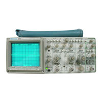
Tektronix 070-7066-02 User Manual (186 pages)
Digital Storage Oscilloscope
Brand:
Tektronix
| Category:
Test Equipment
| Size: 35 MB
Table of Contents
Welcome
5
Related Manuals
5
Table of Contents
7
List of Figures
11
Figure 2-24: Nvmem Reference Menu
12
Product Description
15
Before You Begin
16
Symbols and Terms
17
Specific Precautions
18
Setting up the Display
20
Adjusting Trace Rotation
21
Figure 1-2: Initial Setup Display
21
Figure 1-3: Checking Probe Compensation
22
Installing the Accessory Pouch
23
Figure 1-4: Installing the Accessory Pouch
23
Front Panel
26
Power Switch
29
CRT Display Controls
30
Figure 2-5: CRT Graticule
30
Figure 2-7: Digital (STORE) Mode Display
32
Figure 2-8: CRT Display Controls
33
Vertical Controls and Connections
35
Figure 2-10: Vertical Controls and Connections (Cont.)
37
Horizontal Controls
39
Trigger Controls
41
Figure 2-13: Trigger Controls (Cont.)
43
Figure 2-14: Cursor Controls
45
Memory Buttons
47
Figure 2-18: 4K Two-Channel Acquisition, Memory Location 4K
48
Setup Menus
50
Figure 2-20: Setup Menu Example (Display)
51
Figure 2-21: Acquisition Menu
51
Figure 2-22: Display Menu
53
Figure 2-23: Format Reference Menu
54
Figure 2-26: Advanced Functions Menu
58
Save Setup Menu
58
Figure 2-27: Save Setup Menu
60
Displaying Signals
63
Applying Signals to the Vertical Inputs
63
Figure 3-1: Input Connection and Coupling Switch
63
Connecting Signals
63
Coupling Signals
64
Precharging the Signal Input
64
Building a Basic Display
65
Presetting the Controls
65
Selecting the Display Mode (STORE/NON-STORE)
65
Selecting the Horizontal Mode and Scale
66
Figure 3-2: Horizontal Display Controls
66
Selecting the Vertical Mode and Scale
67
Figure 3-3: Vertical Display Controls
68
Setting the Display Intensity and Focus
68
Finding "Lost" Displays
69
Figure 3-4: CRT Display Controls
69
Selecting the Acquisition Mode
71
Selecting Slow-Speed Storage Modes
71
Viewing Slowly Occurring Events
72
Capturing Random Events
74
Accumulating Signal Peaks (ACCPEAK)
75
Detecting Signal Glitches
75
Clocking Acquisitions
77
Selecting the Acquisition Record Length (1K/4K)
77
Compressing the Acquisition Record Length
78
Positioning the Acquisition Record
79
Preventing Signal Aliases
80
Displaying Magnified Sweeps
81
Using the X10 Magnifier
81
Subtracting Signals or Signal Components (Common Mode Rejection)
82
Displaying Two Sweeps
84
Limiting Bandwidth
87
Modulating the Display Intensity
87
Triggering on Signals
88
Triggering on Low-Frequency Signals
89
Triggering on Random or Infrequent Events
89
Triggering on Complex or Non-Repetitive Signals
90
Triggering on Line Frequency
91
Triggering with an External Signal
91
Triggering on TV Signals
91
Removing Unwanted Trigger Signal Components
93
Measuring Signals
95
Measuring with the Graticule
95
Measuring Voltage
96
Measuring Time with the Graticule or Cursors
99
Measuring Frequency
101
Measuring Trigger Level
104
Measuring Phase Difference
104
Saving and Recalling
107
Saving Waveforms and Setups
107
Saving and Recalling Setups
111
Communicating Via Interface Options
113
Transmitting Waveforms
113
Appendix A: Options and Accessories
118
Option 12: Rs-232-C Interface
118
Other Accessories
120
General Product Description
122
Vertical System
122
Horizontal System
122
Characteristic Tables
125
Vertical Deflection System
125
Trigger System
129
Horizontal Deflection System
131
Probe Adjust
136
Power Supply
137
Appendix C: Performance Verification
142
General Information
142
Performance Check Interval
142
Limits and Tolerances
142
Test Equipment
143
Procedures
145
Initial Setup Procedure
145
Vertical System Checks
145
Horizontal System Checks
154
Trigger System Checks
162
External Z-Axis, Probe Adjust, External Clock, and
168
Appendix D: Storage Modes
172
Advertisement
Tektronix 070-7066-02 User Manual (187 pages)
Digital Storage
Brand:
Tektronix
| Category:
Test Equipment
| Size: 5 MB
Table of Contents
Table of Contents
11
Figure 2-23: Format Reference Menu
14
Figure 2-25: Plot Menu
14
Figure 1-1 : Installing the Power Cord
21
Table 1-1 : Basic Analog Display Setup
22
Figure 1-2: Initial Setup Display
23
Figure 1-3: Checking Probe Compensation
24
Figure 1-4: Installing the Accessory Pouch
25
Figure 1-5: Using the Power Cord Wrap
26
Figure 2-1 : Front Panel Control Sections
28
Figure 2-4: Power Switch
31
Figure 2-5: CRT Graticule
32
Figure 2-7: Digital (STORE) Mode Display
34
Figure 2-8: CRT Display Controls
35
Figure 2-1 0: Vertical Controls and Connections (Cont.)
39
Figure 2-1 1 : Horizontal Controls
41
Figure 2-1 3: Trigger Controls (Cont.)
45
Figure 2-1 4: Cursor Controls
47
Figure 2-15: Acquisition Controls
48
Figure 2-1 6: Save Reference Memory Buttons
49
Figure 2-1 7: 1 K Two-Channel Acquisition, Memory Location 1
50
Figure 2-1 8: 4K Two-Channel Acquisition. Memory Location 4K
50
Figure 2-19: Setup Buttons
52
Figure 2-22: Display Menu
55
Figure 2-26: Advanced Functions Menu
60
Figure 2-27: Save Setup Menu
61
Figure 3-3: Vertical Display Controls
69
Figure 3-4: CRT Display Controls
70
Figure 3-5: Beam Find
71
Figure 3-6: Scan Mode
74
Figure 3-7: Roll Mode
75
Figure 3-8: Accumulate Peak Mode Display
76
Triggering on Line Frequency
92
Triggering on TV Signals
92
Triggering with an External Signal
92
Removing Unwanted Trigger Signal Components
94
Measuring Signals
96
Measuring with the Graticule
96
Measuring with STORE Mode Cursors
96
Positioning the Cursors
97
Measuring Voltage
97
Measuring Voltages in Reference to Ground
98
Measuring Time with the Graticule or Cursors
100
Measuring Time Using the Delay Time Readout
101
Measuring Frequency
102
Measuring Rise Time and Fall Time
103
Measuring Trigger Level
105
Measuring Phase Difference
105
Saving Waveforms and Setups
108
Saving and Recalling Waveforms
108
Saving the Current Acquisition
108
Saving Waveforms in SAVE REF Memory
108
Recalling a Waveform from SAVE REF
109
Comparing Saved Waveforms
109
Formatting Saved Waveforms
109
Saving Waveforms in Long-Term Memory
110
Saving and Recalling Setups
112
Saving a Setup
112
Recalling a Setup from Memory
112
Recalling a Power up State
112
Transmitting Waveforms
114
Communicating Via Interface Options
114
Plotting or Printing a Waveform
115
Appendix A: Options and Accessories
119
Options
119
Table A-1 : International Power Cords
119
Standard Accessories
120
Table A-2: Standard Accessories
120
Other Accessories
121
Table A-3: Optional Accessories
121
Appendix B: Specification
123
General Product Description
123
Options and Accessories
125
Performance Conditions
125
Characteristic Tables
126
Table A-4: Electrical Characteristics
126
Table A-5: Environmental Characteristics
140
Table A-6: Physical Characteristics
141
Appendix C: Performance Verification
143
General Information
143
Purpose
143
Performance Check Interval
143
Structure
143
Limits and Tolerances
143
Test Equipment Required
144
Table A-7: Test Equipment Required
144
Procedures
146
Initial Setup Procedure
146
Vertical System Checks
146
Table A-8: Deflection Accuracy Limits
148
Table A-9: Storage Deflection Accuracy
149
Table A-1 0: Settings for Bandwidth Checks
151
Horizontal System Checks
155
Table A-1 1 : Settings for Timing Accuracy Checks
158
Table A-12: Settings for Delay Time Differential Checks
161
Trigger System Checks
163
Table A-13: Switch Combinations for a Triggering Checks
164
External Z.axis. Probe Adjust. External Clock. and X-Yplotterchecks
169
Appendix D: Storage Modes
173
Glossary
175
Index
181
Advertisement
Related Products
Tektronix 070-9895-03
Tektronix 070-9731-05
Tektronix 070-8523-05
Tektronix 070-9472-02
Tektronix 070-9476-00
Tektronix 070-8592-00
Tektronix 070-8512-01
Tektronix 070-8688-01
Tektronix 071-0957-03
Tektronix 071-0566-03
Tektronix Categories
Test Equipment
Measuring Instruments
Amplifier
Portable Generator
Printer
More Tektronix Manuals
Login
Sign In
OR
Sign in with Facebook
Sign in with Google
Upload manual
Upload from disk
Upload from URL