Sign In
Upload
Manuals
Brands
Technics Manuals
Cassette Player
RS-DV290EG
Technics RS-DV290EG Manuals
Manuals and User Guides for Technics RS-DV290EG. We have
1
Technics RS-DV290EG manual available for free PDF download: Service Manual
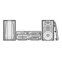
Technics RS-DV290EG Service Manual (268 pages)
Brand:
Technics
| Category:
Cassette Player
| Size: 11.18 MB
Table of Contents
Specifications
1
Location of Controls
2
Operation Checks and Component Replacement / Procedures
2
Checking for the Main P.C.B.
2
Checking for the Operation P.C.B.
2
Replacement for the Motor Ass’y, Capstan Belt and Winding Belt
4
Replacement for the Pinch Roller Ass’y and Head Block
9
Replacement for the Cassette Lid Ass’y
9
Replacement for the Cassette Holder
10
To Supply Power Source
11
Service Mode Function of Cassette Mechanism
11
Cassette Tape to be Prepared
11
Deck 1 Mechanism Check
12
Selecting Service Mode
12
Deck 2 Mechanism Check
13
Exiting Service Mode
15
Schematic Diagram Notes
15
Measurements and Adjustments
20
Measurement Condition
20
Measurement Instrument and Special Tool
20
Frequency Counter
20
Head Azimuth Adjustment
21
Tape Speed Adjustment
22
Playback Gain Adjustment
22
Erase Current Confirmation
23
Playback Frequency Response Check
23
Normal Tape Check
24
Recording/Playback / Frequency Response and Gain Check
24
Cro2/Metal Tape Check
25
Checking Procedure for Self-Operation of Cassette Mechanism Ass’y
26
Operation Check Providing with Cassette Tape
26
Operation Check Not Provided with Cassette Tape
27
Connection Diagram between the Mechanism Ass’y and Power Supply
27
Detail View of EJECT Lever
27
Replacement Parts List
28
Mechanism Parts Location
36
Schematic Diagram for Printing with Letter Size
38
Operation Circuit
39
Main Circuit
39
Playback Signal Line
41
Earth Terminal P.C.b.
50
Main P.C.b.
50
Operation P.C.b.
50
Accessories
55
Before Repair and Adjustment
58
About the Protection Circuitry
58
Operating Instructions
59
Operation Checks and Component Replacement Procedures
59
Checking for the AC in P.C.B.
59
Replacement for the Power IC
63
Self-Diagnostic Function
64
To Display the Malfunction Code
64
To Return to the Normal Display
65
Display Contents
65
IC901 (C2BBFD000404): System Control/Fl Drive
70
Terminal Function of Ics
70
Schematic Diagram
70
Rex0966
73
Sa-Dv290Gn
85
Packaging
86
Schematic Diagram for Printing with A4 Size
87
Stereo Tuner/Amplifier
100
Remote Control
100
Before Repair
110
Checking for the FL P.C.B.
110
Wiring Connection Diagram
113
No Mark: Power on
114
Terminal Function of IC's
115
Ic601(C2Bbgf000425):System Control/Fl Drive
115
Rear Panel
119
Before Use
145
How to Replace the Fuse
145
Handling of Traverse Deck (Optical Pickup)
152
Handling Precautions for Traverse Deck
152
Precaution of Laser Diode
152
Replacement Procedure for the Optical Pickup
153
Grounding for Electrostatic Breakdown Prevention
154
Human Body Grounding
154
Work Table Grounding
154
Checking for the DVD Module (1) P.C.B.
155
Follow the (Step 1) - (Step 3) of Item
156
Follow the (Step 1) - (Step 5) of Item
158
Disassembly and Reassembly for Mechanism Base Drive Unit
166
Follow the (Step 1) - (Step 7) of Item
178
Replacement for the Motor Ass’y
178
Replacement for the Optical Pick-Up
179
Canceling Self-Diagnostic Function
185
How to Enter the Mode and Display
185
Self-Diagnosis Function and Service Modes
185
Self-Diagnostic Function for Loading Mechanism
185
DVD Self Diagnostic Function-Error Code
186
Service Mode Table
186
Last Error Code Saved During no PLAY
189
Cancellation
191
Handling after Completing Repair
191
Sales Demonstration Lock Function
191
Setting
191
Firmware Version-Up of the DVD Player
192
Recovery after the DVD Player Is Repaired
192
Service Precautions
192
Cumulative Operation Time Display
193
Overview of each Function
193
Adjustment Procedures
194
Service Tools and Equipment
194
Important Points in Electrical Adjustment
195
Important Points in Optical Adjustment
195
Optical Pickup Tilt Adjustment
195
Storing and Handling Test Discs
195
Remote Control Unit
196
Check after Adjustment
197
Procedure for Screw Lock
197
Type Illustration of IC's, Transistors and Diodes
200
Voltage and Signal Lines
201
Spring
210
Spring
211
Cabinet Parts Location
224
Loading Mechanism Parts Location
225
Interface Circuit
234
Advertisement
Advertisement
Related Products
Technics RS-DV250
Technics RS-DC10
Technics RS-D200
Technics RS-D225W
Technics RS-TR777
TECHNICS RS-AZ6
Technics RS-EH60
Technics RS-B11W
Technics RS-M225
Technics RS-BX828
Technics Categories
Amplifier
Turntable
CD Player
Stereo Receiver
Speaker System
More Technics Manuals
Login
Sign In
OR
Sign in with Facebook
Sign in with Google
Upload manual
Upload from disk
Upload from URL