Sign In
Upload
Manuals
Brands
Tandberg Data Manuals
Storage
SDLT220
Tandberg Data SDLT220 Manuals
Manuals and User Guides for Tandberg Data SDLT220. We have
1
Tandberg Data SDLT220 manual available for free PDF download: Product Manual
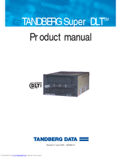
Tandberg Data SDLT220 Product Manual (142 pages)
Brand:
Tandberg Data
| Category:
Storage
| Size: 2 MB
Table of Contents
Table of Contents
7
Introduction
15
Purpose and Scope
15
CHAPTER 1 Introduction
16
CHAPTER 7 Regulatory Compliance
16
Referenced Documents
16
Related Documents
16
Structure of this Manual
16
Conventions
18
For more Information
18
Table 1-1. Typographical Conventions
18
Reader Comments
19
Overview
21
SDLT 220/320 Product Information
21
CHAPTER 2 SDLT 220/320 Product Information
22
SDLT 220/320 Product Features
22
SDLT 220/320 Technology
23
Figure 2-1. SDLT 220/320 Drive System (Photographs)
23
Laser Guided Magnetic Recording
23
Figure 2-2. SDLT 220/320 Drive System (CAD Diagram in Perspective)
24
Magneto Resistive Cluster Heads
24
Pivoting Optical Servo
24
Advanced Metal Powder Media
25
Advanced Partial Response Maximum Likelihood
25
Positive Engagement
25
Figure 2-3. SDLT 220/320 Modular Design
26
Data Control Module
27
Tape Control Module
28
Tcm Pcba
28
Base Plate
28
Cartridge Receiver
28
Positive Engagement Tape Leader Buckling Mechanism
29
Front Panel Module
29
Electronic Interface Module
30
SDLT Cartridge Tape Module
30
SDLT 220/320 Modular Design
26
Tandberg Data Diagnostics Tools
32
Tapealert
33
Drive Specifications
35
Product Specifications
35
Interface Type
36
Physical Dimensions
36
Table 3-1. SDLT 220/320 Physical Dimensions and Shipping Weight
36
Storage Capacity
37
Compression
37
Table 3-2. SDLT 220/320 Storage Capacity
37
Data Integrity
38
Table 3-3. Data Transfer Error Rates
38
Maximum Data Transfer Rate
39
Table 3-4. Maximum Data Transfer Rates
39
Reliability (MTBF)
40
Load and Unload Cycles
40
Functional Specifications
40
Table 3-5. Load and Unload Cycles (Maximum)
40
SDLT 220/320 Performance Data
41
Table 3-6. SDLT 220/320 Performance Data
41
Shock and Vibration Specifications
42
Table 3-7. Non-Operating Shock Specifications (Unpackaged)
42
Table 3-8. Non-Operating Shock Specifications (Packaged, Drop)
42
Table 3-9. Non-Operating Vibration Specifications
43
Current and Power Requirements
44
Table 3-10. Operating Shock and Vibration Specifications
44
Table 3-11. Current and Power Specifications
45
Tape System Recording Method
46
Environmental Specifications
47
Air Flow Requirements
47
Temperature and Humidity
48
Storage and Shipment
48
Table 3-12. Temperature and Humidity Specification
48
Table 3-13. Drive Storage and Shipment Specifications
48
Altitude
49
Particulate Contamination Limits
49
Recording Media Specifications
49
Table 3-14. Particulate Contamination Limits
49
Table 3-15. Super Dlttape I Media Specifications
50
Table 3-16. Dlttape Media Operating and Storage Limits
50
Backward-Read Compatibility Transfer Rates
51
Table 3-17. Backward-Read Compatibility (BRC) Transfer Rates
51
Installing Your Tape Drive
53
Safety, Handling, and ESD Protection
54
Safety Precautions
54
Handling
55
Electrostatic Discharge Protection
56
Pre-Installation Guidelines
57
Configuring and Installing an Internal Tape Drive
58
Setting the Internal Drive SCSI ID
59
Figure 4-1. Connectors on the Back Panel
60
Figure 4-2. Back Panel Connector Locations (Drawn to Scale)
60
Table 4-1. SCSI ID Address Selections
61
Configuring the Internal Drive for TERMPWR
62
Configuring the Internal Drive for Narrow SCSI
62
Installing the Internal Tape Drive
62
Figure 4-3. TERMPWR Connector
62
Figure 4-4. SDLT 220/320 - Two Views (Front + Side + Top and Back + Side + Top)
63
Securing the Internal Tape Drive
63
Connecting the Internal Drive Cables
64
Figure 4-5. Internal Drive Mounting Locations - Side and Bottom Views
64
Figure 4-6. Connectors on the Back Panel (Drawn to Scale)
66
Table 4-2. MSE and SE Mode SCSI Connector Pin Assignments
66
Table 4-3. MSE LVD Mode SCSI Connector Pin Assignments
68
Table 4-4. HVD Mode SCSI Connector Pin Assignments
69
Table 4-5. 4-Pin Power Connector Pin Assignments
71
Table 4-6. 8-Pin Loader Connector Pin Assignments
71
Configuring and Installing a Tabletop Drive
72
Configuring the Drive
72
Figure 4-7. Back Panel of the Tabletop Model
72
Installing the Tabletop Drive
73
SCSI Cables
73
AC Power Cable
74
Confirming the Installation
75
Figure 4-8. AC Power Cord Connector Types
75
Using Your Tape Drive
77
Performing a Trial Back-Up
78
Power on Self Test
78
Table 5-1. Indicator Pattern During POST
78
CHAPTER 2 SDLT 220/320 Product Information
16
CHAPTER 3 Drive Specifications
16
CHAPTER 4 Installing Your Tape Drive
16
CHAPTER 5 Using Your Tape Drive
16
CHAPTER 6 SCSI Description
16
APPENDIX Bdlt IV Tape Cartridge
79
Overwriting 320-Formatted Cartridges in a 220 Drive
79
Updating the Firmware
80
Update the Firmware Using the SCSI Bus
80
Making a FUP/CUP Tape
81
Using a CUP/FUP Tape
81
Troubleshooting the Firmware (Code) Update
82
Cleaning the Tape Mechanism
83
Occasional Cleaning of Tape Head
83
When to Use the Cleaning Tape
84
Life Expectancy of the Cleaning Tape
84
Compatibility of the Cleaning Tape
84
Loading the Cleaning Tape into a Tabletop Drive
85
Front Panel Controls and Leds
86
Table 5-2. Behavior of the Amber LED When a Tape Cartridge Is Loaded
86
Figure 5-1. SDLT 220 and SDLT 320 Front Panels (a Comparison)
87
Table 5-3. Front Panel Led/Control Functionality
88
Troubleshooting
89
POST Troubleshooting
89
Table 5-4. Troubleshooting Chart
89
Over Temperature Condition
91
SCSI Description
93
SCSI Overview
93
SCSI-2 Commands
95
Table 6-1. Implemented ANSI SCSI-2 Commands
95
SCSI-3 Commands
97
Table 6-2. Implemented ANSI SCSI-3 Commands
97
Parity
98
Signal States
98
Signal Values
98
Table 6-3. ANSI Signal Sources
99
SCSI Ids
100
SCSI Signals
100
SCSI Signal Definitions
101
Table 6-4. SCSI-2 Bus Signal Definitions
101
Signal Bus Timing
102
Table 6-5. SCSI Bus Timing Values
102
Regulatory Compliance
105
Safety Regulations
105
Safety Certifications
105
Safety Requirements
106
Electromagnetic Field Specifications
106
Electromagnetic Emissions
106
Electromagnetic Interference Susceptibility
107
Conducted Emissions
107
Table 7-1. EMI Regulations and Certifications
107
Table 7-2. Conducted Emissions
107
Radiated Emissions
108
Table 7-3. Radiated Emissions
108
Susceptibility and ESD Limits
109
Table 7-4. Radiated, Magnetic Radiated, and Conducted Susceptibility
109
Table 7-5. Electrostatic Discharge (ESD) Failure Level Limits
109
Acoustic Noise Emissions
110
Table 7-6. Acoustic Noise Emissions, Nominal
110
APPENDIX Asdlt I Tape Cartridge
112
Tape Cartridge Handling Guidelines
112
APPENDIX Asdlt I Tape Cartridge
113
Tape Cartridge Inspection Procedure
113
Figure A-1. End View of SDLT I Cartridge
114
Figure A-2. Bottom View of SDLT I Cartridge
114
Figure A-3. Write-Protect Switch on Tape Cartridge
115
Tape Cartridge Write-Protect Switch
115
Table A-1. Write-Protect Switch Positions
116
Figure A-4. Front Panel Leds
117
Loading a Tape Cartridge
117
Overwriting 320-Formatted SDLT Tape Cartridges
118
Unloading a Tape Cartridge
118
APPENDIX Bdlt IV Tape Cartridge
122
Tape Cartridge Handling Guidelines
122
Tape Cartridge Inspection Procedure
123
Figure B-1. End View of DLT Cartridge
124
Figure B-2. Bottom View of DLT Cartridge
124
Figure B-3. DLT Tape Leader Loop in Its Correct Position
125
Figure B-4. Tape Cartridges with Damage Visible During Visual Inspection
126
Figure B-5. Write-Protect Switch on Tape Cartridge
127
Tape Cartridge Write-Protect Switch
127
Figure B-6. Front Panel Leds
128
Loading a Tape Cartridge
128
Unloading a Tape Cartridge
129
Glossary
131
Advertisement
Advertisement
Related Products
Tandberg Data SDLT 600
Tandberg Data SDLT320 -
Tandberg Data SDLT220-320 INTEGRATION
Tandberg Data SDLT 320
Tandberg Data SDLT 220
Tandberg Data SLR24
Tandberg Data SLR50
Tandberg Data SLR60
Tandberg Data Storagelibrary T24
Tandberg Data SLR
Tandberg Data Categories
Storage
Network Hardware
Network Storage Server
Software
Server
More Tandberg Data Manuals
Login
Sign In
OR
Sign in with Facebook
Sign in with Google
Upload manual
Upload from disk
Upload from URL