Sign In
Upload
Manuals
Brands
Tally Manuals
Printer
T6215
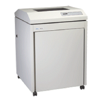
Tally T6215 Line Matrix Printer Manuals
Manuals and User Guides for Tally T6215 Line Matrix Printer. We have
1
Tally T6215 Line Matrix Printer manual available for free PDF download: Maintenance Manual
Tally T6215 Maintenance Manual (164 pages)
Brand:
Tally
| Category:
Printer
| Size: 10 MB
Table of Contents
Table of Contents
5
Preface
13
About this Manual
13
Chapter 2. Menu Operations
13
Chapter 3. Faults and Troubleshooting
13
Chapter 4. Removing and Replacing Components
13
Appendix A. Schematics and Illustrated Parts Breakdowns
13
Appendix B. Downloading Printer Firmware
13
Conventions
13
Chapter 1: Technical Overview
13
Technical Overview
15
T6215 Electronic Hardware Architecture
17
Control Processor
17
Engine Control Module
17
Sensor Inputs
17
Altera EPM7064
18
Eeprom
18
Main Processor
18
Motor Logic and Drive
18
Motorola Cold Fire 5307
18
Parallel
18
Serial
18
Serial and Parallel Interfaces
18
Table 1–1. Host Interface Configurations
18
Hammer Drive Module
19
Specifications
19
Characters Per Inch
19
Courier and Gothic
19
Data Processing and Draft
19
Font Styles
19
OCR-A and OCR-B
19
Serial/Parallel Emulations
19
Lines Per Inch
20
Table 1–2. Type Style, Character Matrix, Dot Density, and CPI Combinations
20
Dot Densities and Plot Speeds
21
Graphics Benchmarks
21
Table 1–3. Plot Data Output Speed
21
Table 1–4. AIAG Label Benchmark Results
21
Table 1–5. POSTNET Label Benchmark Results
21
Acoustics
22
Cooling System
22
Forms/Paper Description
22
Paper Slew Speed
22
Power Supply
22
Ribbons
22
Table 1–6. Slew Speed
22
Table 1–7. Power Requirements
22
Environment
23
Heat Load Contribution
23
Nonoperating
23
Operating
23
Preventive Maintenance
23
Safety
23
Table 1–8. Heat Load Contribution
23
Agency Approvals
24
Electromagnetic Emissions
24
Industry and Agency Standards
24
Physical Configuration
24
Printer Dimensions
24
Table 1–9. Printer Dimensions
24
Weight
24
Chapter 2: Menu Operations
25
Introduction
27
Technical Access Mode
27
How to Enter Tech Access Mode
27
How to Exit Tech Access Mode
27
Testing, Troubleshooting and Calibration
27
Printer Tests
27
Help Menu
28
Hex Dumps
28
Printer Information Printouts and Displays
28
Printing a HELP Menu in Tech Access Mode
28
Report
29
Report Selections
29
Selecting a Printer Report
29
TEST Menu
30
Table 2–1 Test Menu
30
Pattern Category
32
Print
32
Print Selections
32
Print2
32
Print2 Selections
32
Plot
33
Plot Selections
33
Fault Override Category
34
Hammer
34
Paper Motion
34
Paper out
34
Selecting and Running a Print Test
34
Calibrations
35
Control
35
Diagnostic Category
35
Link
35
Platen
35
Ribbon Motion
35
Shuttle
35
Sync
35
Temp
35
Selecting and Running a Hammer Calibration Routine
36
Figure 2–1. Hammer Leadtime Calibration Printout Sample (Partial)
37
Selecting and Running a Platen Gap Calibration Routine
37
Accessing the Meter Measurement Tests
38
Meter
38
Accessing the Motor Tests
39
Motor Selections
39
Motors
39
Ribbon Speed
39
Shuttle Speed
39
Shuttle Speed Selections
39
Speed Selections
39
Clear
40
Clear Selections
40
Energy Star
40
Paper out Thold
40
Ribbon Ink, Dots Per Pump
40
Ribbon Threshld
40
Serial Dump
40
Shuttle Change
40
Shuttle off
40
Threshold Selections
40
ALL Fault Reporting
41
Control Panel Key Operations for Controlling Fault Reporting
41
Four Faults Only
41
Paper out Only
41
Chapter 3: Faults and Troubleshooting
43
Faults
45
Table 3–1. Display Messages
47
The Printer Does Not Power up When Switched on
54
The Printer Powers up but the Control Panel Does Not Function
55
The Control Panel Display Functions Partially, Nonsensically, or Not at All
55
There Is no Printed Output but the Printer Appears to be Operating Normally
56
Printed Output Appears Light
56
Printed Output Appears Shaky or Fuzzy
57
Character Columns Not Printing
57
The Printer Is out of Paper - no Paper out Fault Is Reported
59
No Paper Motion - no Paper Motion Fault Is Reported
59
Table 3–2. Paper/Printing Corrective Action
60
Figure 3–1. Power on Troubleshooting Sequence
62
Figure 3–1A. Power on Troubleshooting Sequence, Continued
63
Figure 3–2. Print Data Troubleshooting Sequence
64
Figure 3–2A. Print Data Troubleshooting Sequence, Continued
65
Figure 3–2B. Print Data Troubleshooting Sequence, Continued
66
Figure 3–2C. Print Data Troubleshooting Sequence, Continued
67
Figure 3–2D. Print Data Troubleshooting Sequence, Continued
68
Chapter 4: Removing and Replacing Components
69
Introduction
71
Required Tools
71
T6215 Maintenance Manual Service Procedures
72
Service Procedures
72
Figure 1. Loosening Screws on Ribbon Platform
73
Figure 2. Unplugging Ribbon Drive Motor Cable
73
Figure 3. Removing Motor Screws
74
Figure 4. Unplugging Ribbon Motor Cables
74
Procedure 2: Ribbon Motor Removal
74
Ribbon Motor Removal
74
Procedure 1: Ribbon Platform Removal
73
Figure 5. Removing PCA Screws
75
Procedure 3: Ribbon Motion Sensor PCA Removal
75
Procedure 4: Control Panel Removal
76
Control Panel Removal
76
Figure 6. Unplugging Control Panel Cable
76
Procedure 4A: Control Panel Circuit Board Removal
77
Figure 7. Removing Circuit Board Screws
77
Procedure 5: Hammer Bank Removal
78
Hammer Bank Removal
78
Figure 8. Removing Plastic Cable Cage
78
Figure 9. Unplugging Hammer Bank Ribbon Cables
78
Figure 10. Removing Screws on Retainer Clips
79
Figure 11. Removing Nuts from Underneath Hammer Bank
79
Figure 12. Lifting Hammer Bank from Printer
80
Figure 13. Replacing Shuttle Drive Belt
80
Procedure 6: Ribbon Shield Removal
81
Ribbon Shield Removal
81
Figure 14. Removing the Ribbon Shield
81
Procedure 7. 13-Pack Hammer Replacement
82
Pack Hammer Replacement
82
Figure 15. Measuring Old Hammer for Replacement Size
82
Figure 16. Aligning the New Hammer Pack
83
Figure 17. Coil Board Replacement
84
Procedure 8: Coil Board Replacement
84
Procedure 9: Shuttle Removal
85
Shuttle Removal
85
Figure 18. Removing Shuttle Screws
85
Figure 19. Removing Screws from Inside Shuttle
85
Procedure 10: Platen Removal
86
Platen Removal
86
Figure 20. Location of Circuit Board
86
Figure 21. Removing the Platen Springs
87
Figure 22. Removing Screws from the Platen Stop
88
Platen Gap Adjustment
88
Figure 23. Transferring Components from Old to New Platen
89
Figure 24. Adding Grease
90
Procedure 11: Platen Gap Adjustment
92
Figure 25. Platen Adjustment Screws and Use of Shim
93
Procedure 12: Print Mechanism Access (Tilting)
94
Print Mechanism Access (Tilting)
94
Figure 26. Unplugging the Power Supply Cable
94
Figure 27. Print Mechanism Tilted and Held by Strut
95
Procedure 13: Distribution PCA Removal
96
Distribution PCA Removal
96
Figure 28. Removing Screws on Mounting Bracket
96
Procedure 14: Lower Tractor Removal
97
Lower Tractor Removal
97
Figure 29. Location of Paper out Sensor Cables
97
Figure 30. Removing Retaining (Snap) Rings
97
Figure 31. Ground Spring
98
Figure 32. Round and Square Shafts
98
Procedure 15: Upper Tractor Removal
100
Upper Tractor Removal
100
Procedure 16: Tractor Phasing/Paper Drive Belt Tension Adjustment
101
Tractor Phasing/Paper Drive Belt Tension Adjustment
101
Figure 33. Tractor Phasing and Paper Drive Belt
101
Figure 34. Paper Tension Lever in Middle Position
102
Figure 35. Placing the Phasing Gauge
102
Figure 36. Placing Tension Gauge
103
Figure 37. Placing Paper Tension Gauge
104
Procedure 17: Paper Drive Motor Removal
105
Paper Drive Motor Removal
105
Figure 38. Paper Drive Motor Location
105
Procedure 18: Shuttle Motor Removal
106
Shuttle Motor Removal
106
Figure 39. Shuttle Motor
106
Figure 40. Front of Control PCA Assembly after Cover Has Been Removed
107
Procedure 19: Control PCA Assembly Removal
107
Procedure 20: Power Supply Assembly Removal
108
Power Supply Assembly Removal
108
Figure 41. Power Supply Assembly
108
Firmware Update Procedure
151
Advertisement
Advertisement
Related Products
Tally T6218
Tally T6140
Tally T6141
Tally T6090
Tally T2030
Tally T2130
Tally T2030/24
Tally T9112
Tally T9014
Tally T9120
Tally Categories
Printer
Server
Printer Accessories
All in One Printer
Print Server
More Tally Manuals
Login
Sign In
OR
Sign in with Facebook
Sign in with Google
Upload manual
Upload from disk
Upload from URL