Sign In
Upload
Manuals
Brands
Tainet Manuals
Gateway
VENUS 2908-8S
Tainet VENUS 2908-8S Manuals
Manuals and User Guides for Tainet VENUS 2908-8S. We have
1
Tainet VENUS 2908-8S manual available for free PDF download: User Manual
Tainet VENUS 2908-8S User Manual (225 pages)
VoIP SIP Gateway
Brand:
Tainet
| Category:
Gateway
| Size: 4 MB
Table of Contents
Voip Gateway
1
About this Manual
4
Limited Warranty
6
Table of Contents
8
Chapter 1. Overview
17
Product Overview
17
Applications
20
Figure 1-1 Typical SIP Voip Application
20
Figure 1-2 Enterprise Voip Intranet Application
21
Figure 1-3 MTU/MDU Application
21
Product Description
22
Hardware Architecture
22
Figure 1-4 Front View of VENUS 2932
22
Figure 1-5 Rear View of VENUS 2932
22
Figure 1-6 Front View of VENUS 2924
22
Figure 1-7 Rear View of VENUS 2924
22
Figure 1-8 Front View of VENUS 2916
23
Figure 1-9 Rear View of VENUS 2916
23
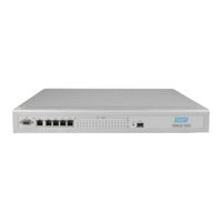
Figure 1-10 Front View of VENUS 2908-8S
23
Figure 1-11 Rear View of VENUS 2908-8S
23
Figure 1-12 Front View of VENUS 2908-4S4O
23
Software Architecture
24
Figure 1-13 Rear View of VENUS 2908-4S4O
24
Figure 1-14 Web Browser
26
Technical Specifications
27
Table 1-1 VENUS 29XX Series Technical Specification
27
Standard Compliance
31
Chapter 2. Hardware Installation
33
Unpacking
33
Site Requirements
34
Site Selection
34
AC Electrical Outlet Connection
34
Grounding
34
Led Indicators
36
Table 2-1 LED Description
36
Cable Connection
37
Connecting the Power Source
37
Connecting the IP Network Via Ethernet
37
Table 2-2 10/100Base-T Connection
37
Connecting the Terminal
38
Connecting the Telephony Devices
38
Figure 2-1 VENUS 2908-8S Series Telephony Interface
38
Figure 2-2 VENUS 2908-4S4O Series Telephony Interface
38
Table 2-3 Venus2916 RJ-21Pin Assignment
39
Table 2-4 Venus2924/2932 First RJ-21Pin Assignment
39
Table 2-5 Venus2932 Second RJ-21Pin Assignment
40
Figure 2-3 Twisted Pair Cable
41
Table 2-6 Twisted Pair Pin Assignment
41
Hardware Diagnosis
42
Chapter 3. Configuration and Management
43
Quick Start
43
Connecting to Venus 29Xx
43
Figure 3-1 Connecting to the PC
44
Table 3-1 Terminal Emulation Software
44
Figure 3-2 the Login Page
45
Figure 3-3 the Login CLI Screen
46
Figure 3-4 the Root Menu of the Web Site
46
Figure 3-5 the Root Screen
47
Figure 3-6 the Command List Screen
47
Figure 3-7 Set Ethernet Interface
48
Complete the "Quick Start" Configuration
49
Figure 3-8 the Quick Start Web Page
50
Table 3-2 Network Connection Mode Configuration
50
Figure 3-9 Network Connection Mode Configuration
51
Table 3-3 Static IP Configuration
51
Figure 3-10 Static IP Configuration
52
Table 3-4 SIP Server Configuration
52
Figure 3-11 SIP Server Configuration
53
Table 3-5 FXS/FXO Configuration
54
Figure 3-12 FXS/FXO Configuration
55
Figure 3-13 Saving the Configure Information
55
Figure 3-14 Quick Start Completed
56
Figure 3-15 Check FXS/FXO State
56
Quick Setup
57
Login
57
Main Page
57
Figure 3-16 Login Page
57
Network Setting
58
Figure 3-17 Main Page
58
Figure 3-18 Network Configuration
58
SIP Setting
59
Analog (FXS/FXO) Setting
59
Figure 3-19 SIP Realm
59
Status Check
60
Figure 3-20 Analog (FXS/FXO) Settings
60
Figure 3-21 Status Check
60
Login and Logout
61
Figure 3-22 Web-Based Login Interface
61
Table 3-6 VENUS 2908 User
61
Navigating the Web Interface
62
Figure 3-23 Terminal Emulation-Based Login Interface
62
Figure 3-24 Web UI Main Page
63
Table 3-7 Main Menu Tree
63
Configuration
64
Table 3-8 the Configuration Menu Items
64
Figure 3-25 Prompt of "Save & Run
65
Figure 3-26 Prompt after Click "OK" Button on "Save & Run" Page
65
Save & Run
65
Interface Configuration
66
Table 3-9 the Interface Configuration Menu Items
66
Figure 3-27 Ethernet Configuration
67
Table 3-10 Description of Ethernet Configuration Items
68
Figure 3-28 Prompt after Click "OK" Button
69
Figure 3-29 Analog (FXS/FXO) Configuration
70
Table 3-11 Description of Analog (FXS/FXO) Configuration Items
70
Figure 3-30 3G Modem
73
Figure 3-31 Analog (FXS/FXO) Configuration
74
Table 3-13 Description of PSTN Lifeline Items
74
Figure 3-32 System General Configuration
75
System Configuration
75
Table 3-14 the System Configuration Menu Items
75
Table 3-15 Description of System General Items
75
Figure 3-33 NTP Configuration
76
Table 3-16 Description of NTP Items
76
Figure 3-34 User Management Configuration
77
Table 3-17 Description of User Management Items
77
Figure 3-35 UI Management Configuration
78
Table 3-18 Description of UI Management Items
78
Figure 3-36 Provisioning Configuration
79
Table 3-19 Description of Provisioning Items
79
Figure 3-37 SNMP Configuration
81
Table 3-20 Description of SNMP Items
82
Figure 3-38 TR069 Configuration
83
Table 3-21 Description of TR069 Items
83
Figure 3-39 FM Configuration
84
Figure 3-40 Syslog Configuration
85
SIP Configuration
86
Figure 3-41 SIP General Configuration
87
Table 3-24 Description of SIP General Configuration Items
87
Figure 3-42 SIP Realm Configuration
90
Table 3-25 Description of SIP Realm Configuration Items
91
Figure 3-43 SIP Group Configuration for 8S and 4S4O Model
93
Table 3-26 Description of SIP Group Configuration Items
94
Figure 3-44 SIP Phone Routing Table Configuration
95
Table 3-27 Description of SIP Phone Routing Table Configuration Items
95
Figure 3-45 SIP Digit Manipulation Configuration
97
Advanced Configuration
98
Figure 3-46 RTP Management Configuration
99
Table 3-29 Description of RTP Management Configuration Items
99
Figure 3-47 Calling Feature Configuration
102
Table 3-30 Description of Calling Feature Configuration Items
102
Table 3-31 Call Waiting Operation
107
Table 3-32 Call Conference Normal Operation
107
Table 3-33 Call Conference by Refer Operation
109
Table 3-34 Call Conference by Star Number Operation
110
Table 3-35 Call Conference by Flash Number Operation
111
Figure 3-48 Region Configuration
112
Table 3-36 Attended Call Transfer Operation
112
Table 3-37 Unattended Call Transfer Operation
112
Table 3-38 Description of Region Configuration Items
113
Figure 3-49 Ring Configuration
114
Table 3-39 Description of Ring Configuration Items
114
Figure 3-50 Tone Configuration
115
Table 3-40 Description of Tone Configuration Items
115
Figure 3-51 DDNS Configuration
117
Table 3-41 Description of DDNS Configuration Items
117
Figure 3-52 NAT Traversal Configuration
118
Table 3-42 Description of NAT Traversal Configuration Items
118
Figure 3-53 SLIC Configuration
119
Figure 3-54 Meter Configuration
119
Data Configuration
120
Table 3-45 the Data Configuration Menu Items
120
Figure 3-55 Static Routing Configuration
121
Figure 3-56 NAT Mapping Configuration
122
Table 3-46 Description of Static Routing Items
122
Table 3-47 Description of NAT Mapping Items
123
Figure 3-57 DHCP Server Configuration
124
Table 3-48 Description of DHCP Server DHCP Items
125
Figure 3-58 DHCP Server Configuration
126
Table 3-49 Description of DHCP Server Assign Items
126
Figure 3-59 Qos Configuration
127
Table 3-50 Description of Qos Items
127
Figure 3-60 Port Based Vlan Configuration
128
Figure 3-61 Vlan Tag Configuration
128
Table 3-51 Description of Vlan Items
128
Maintenance
129
Fault Management
129
Table 3-52 the Maintenance Menu Items
129
Table 3-53 the Fault Management Menu Items
129
Figure 3-62 FM Monitoring
130
Table 3-54 Description of FM Monitoring
130
Performance Management
131
Figure 3-63 FM Clear
131
Table 3-55 the Performance Management Menu Items
131
Figure 3-64 Ethernet Performance
132
Figure 3-65 Call Control Status
132
Figure 3-66 RTP Status
133
Figure 3-67 SIP Agent Status
133
Diagnostics
134
Figure 3-68 SIP Call Initiation Status
134
Figure 3-69 Clear Performance Message
134
Table 3-56 the Fault Management Menu Items
134
Figure 3-70 Ping
135
Figure 3-71 Result of Ping a Connected IP Device
135
Figure 3-72 Result of Ping a Disconnected IP Device
135
Device Control
136
Figure 3-73 Stun
136
Figure 3-74 Result of Stun a Disconnected Stun Server
136
Figure 3-75 Traceroute
136
Table 3-57 the Device Control Menu Items
136
Figure 3-76 Firmware Upgrade
137
Table 3-58 Description of Firmware Upgrade Items
137
Figure 3-77 Step 1 of F/W Upgrading
138
Figure 3-78 Step 2 of F/W Upgrading
139
Figure 3-79 F/W Upgrading Failure
140
Figure 3-80 Step 3 of F/W Upgrading
140
Figure 3-81 Step 4 of F/W Upgrading
141
Figure 3-82 Config Up/Down
141
Table 3-59 Description of Config Up/Down Items
142
Figure 3-83 Set Config Uploading Parameters
143
Figure 3-84 Config Uploading
143
Figure 3-85 Config Uploading Failure
144
Figure 3-86 Set Config Downloading Parameters
144
Figure 3-87 Config Downloading
145
Figure 3-88 Config Downloading Failure
145
Figure 3-89 Syslog Upload
146
Figure 3-90 Reset to Default
147
Figure 3-91 Reset Finished
147
Figure 3-92 Reset to Default
148
Figure 3-93 Reboot Finished
148
Status
149
System Information
149
Ethernet
149
Figure 3-94 System Information Status
149
3Gmodem Info
150
Figure 3-95 Ethernet Status
150
Analog (FXS/FXO)
151
Routing Table
151
ARP Table
151
Figure 3-96 Analog Status
151
Figure 3-97 Routing Table Status
151
Fxs to Fxo Line Extension Example
152
Figure 3-98 ARP Table Status
152
Table 3-61 Description of Routing Table Monitoring Items
152
Navigation the Command Line Interface
160
Figure 3-100 Main CLI Tree
161
Figure 3-99 CLI Main UI
161
Table 3-62 the Main CLI Tree
161
Figure 3-101 Status Commands
162
Status Commands
162
Syntax
162
Configuration Commands
163
Figure 3-102 Prompt of Save Command
163
Figure 3-103 Set Command
163
Table 3-64 Save Command
163
Table 3-65 Set Command Items
164
Figure 3-104 Show Command
165
Table 3-66 Show Command Items
166
Maintenance Commands
167
Figure 3-105 Maintenance Commands
168
Table 3-67 Mt Command Items
168
Other Commands
169
Figure 3-106 Spy Command
170
Table 3-68 Spy Level
171
Chapter 4. Edit Configuration File
173
File Format
173
Example File
173
Chapter 5. Troubleshooting
217
Instruments
217
Troubleshooting
217
Table 5-1 Voice Codec Bandwidth
220
Appendix A Supplemental Telephone Features
221
Table A-1 Supplemental Telephony Features
221
Appendix B Abbreviation
223
Advertisement
Advertisement
Related Products
Tainet VENUS 2908-4S4O
Tainet VENUS 2932
Tainet VENUS 2916
Tainet VENUS 2924
Tainet Venus Series
Tainet WANpro 2000i
Tainet DT-2000 Series
Tainet Categories
Modem
Gateway
Network Router
Conference System
Network Hardware
More Tainet Manuals
Login
Sign In
OR
Sign in with Facebook
Sign in with Google
Upload manual
Upload from disk
Upload from URL