Sign In
Upload
Manuals
Brands
Tabor Manuals
Inverter
8020
Tabor 8020 Manuals
Manuals and User Guides for Tabor 8020. We have
1
Tabor 8020 manual available for free PDF download: User Manual
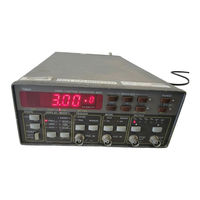
Tabor 8020 User Manual (111 pages)
20 MHz Programmable Function Generator
Brand:
Tabor
| Category:
Inverter
| Size: 2.48 MB
Table of Contents
Safety Precautions
4
Declaration of Conformity
5
Table of Contents
6
Section 1. General Information
14
Introduction
14
Description
14
Instrument and Manual Identification
15
Options
15
Specifications
15
Safety Consideration
15
Accessories Supplied
15
General Information
18
Section 2. Installation
20
Introduction
20
Unpacking and Initial Inspection
20
Performance Checks
20
Power Requirements
20
Grounding Requirements
20
Installation and Mounting
21
Bench Operation
21
Rack Mounting
21
Portable Use
21
Short Term Storage
21
Long Term Storage or Repacking for Shipment
21
Safety
22
Section 3. Operation
24
Introduction
24
Front Panel Familiarization
24
Controls
24
Status
24
Display/Modify
24
Front Panel Controls, Indicators and Connectors
25
Trigger Mode
26
Operating Mode
26
Output
26
Modifier
26
Connectors
26
Operating Instructions
26
Display and Indicators
27
Rear Panel Familiarization
27
Connectors and Switches
27
Power-Up Procedure
27
Software Reset
28
Parameter Preset
28
Display Messages
29
Detecting Programming Errors
29
General Error
29
Pulse/Ramp Set-Up Errors (Model 8021 Only)
29
Offset Errors
29
IEEE-488 Errors
30
Selecting 2Nd Functions
30
Modifying Parameters
30
Modifier
31
Range
31
Parameter Limits
31
Front Panel Parameter Entry Limits
31
Selecting an Output Waveform
32
Disabling the Output
32
Selecting an Operating Mode
32
Function Generator Mode
32
Sweep Generator Mode
32
Selecting Sweep Direction
32
Voltage Controlled Oscillator Mode
33
Pulse Generator Mode (Model 8021 Only)
33
AM Mode (Model 8022 Only)
34
Triggering the Pulse Generator
34
Using Front Panel Set-Ups
34
Store Set-Ups
34
Recall Set-Ups
35
Using the Recall Mode
35
Using the Offset
35
Changing the GPIB Address
35
Section 4. Ieee Programming
36
Introduction
36
Bus Description
36
IEEE-488 Bus Lines
37
Bus Managment Lines
37
Handshake Lines
38
Data Lines
39
Interface Function Codes
39
Software Considerations
39
Hardware Consideration
40
Typical Controlled Systems
40
Connections
40
Changing GPIB Address
40
Bus Commands
41
Uniline Commands
41
Universal Multiline Commands
42
Addressed Commands
43
Unaddress Commands
44
Device Dependent Commands
44
Common Commands and Queries
44
Device Listing Formats
44
Function Element Summary
45
Seperator Function Element Summary
45
Program Message Unit Seperator
45
Program Data Seperator
46
Program Message Terminator
46
Command Program Header
46
Query Program Header
46
Program Data
46
Decimal Numeric Program Data
46
Suffix Program Data
47
Arbitrary Block Program Data
47
Expression Program Data
47
Device-Dependent Command Programming
47
Operating Mode (P,V,A,O)
51
Trigger Mode (G,T)
51
Output Mode (C,B)
51
Waveform (U)
51
Parameter Programming
51
Common Commands
53
Set-Ups (*SAV, *RCL)
53
Device Talking Formats
53
Function Element Summary
54
Response Message Unit Seperator
54
Response Data Seperator
54
Response Header Seperator
54
Response Message Terminator
54
Response Header
55
Response Data
55
Character Response Data
55
Decimal Numeric Response Data
55
Reading from the Model 8020
55
Interrogate Parameter Data Query
56
Common Queries
56
Response Header (X)
56
Response Message Terminator
57
Device Status Reporting
57
Status Byte Register
57
Reading the Status Byte Register
58
Reading with a Serial Poll
58
Reading with the *STB
58
Clearing the Status Byte Register
58
Service Request Enable Register
58
Standard Event Status Register (ESR)
59
Standard Event Status Register (ESE)
60
IEEE-488.2 Status Reporting Model
60
Machine Status Register (STT)
61
Front Panel Error Messages
61
ILI (Illegal Instruction) Error
61
ILP (Illegal Parameter) Error
61
Section 5. Maintenance and Performance Checks
62
Introduction
62
Line Voltage Selection
62
Fuse Replacement
62
GPIB Interface Option Field Installation (Option 1)
62
Option 1 Installation Procedure
63
Special Handling of Static Sensitive Devices
64
Cleaning
64
Repair and Replacement
64
Performance Checks
64
Environmental Conditions
64
Warm-Up Period
64
Recommended Test Equipment
64
Performance Checks Procedure
65
Frequency - Gated Mode
65
Frequency - Continuous Mode
65
Amplitude
66
DC Characteristics
66
Squarewave Characteristics
66
Sine Characteristics
66
Sine Flatness
67
Trigger, Gate, Manual
67
Sweep
67
VCO Control
68
Pulse Width (Model 8021)
68
Amplitude Modulation (Model 8022)
69
Section 6. Theory of Operation
70
Introduction
70
Overall Functional Description
70
Analog Circuitry
70
Current Generator
70
Theory of Operation
71
Voltage Controlled Oscillator
72
Sine Shaper
73
Trigger Circuit
73
Model 8020 - Clamp Circuit Simplified Diagram
74
Pulse Shaper
75
Preamplifier
75
Attenuator
76
Offset Generator
76
Power Amplifier
76
Post Amplifier Attenuator
76
Power Supply
76
Pulse Generator Circuit (Model 8021)
76
Pulse Generator Functional Block Diagram
77
AM Circuit (Model 8022)
78
Digital Circuitry
78
Display and Keyboard Interface
78
Counter Circuit
79
IEEE-488 Interface (Option 1)
79
Section 7. Adjustments
80
Introduction
80
Adjustments
80
Environmental Conditions
80
Warm-Up Period
80
Recommended Test Equipment
80
Adjustment Procedures
80
Adjustment Procedure
81
Power Supply Adjustment
81
Distortion Adjustment
81
Frequency Adjustment
81
Low Frequency Adjustment
81
Low Frequency Distortion Adjustment
81
Trigger Start Phase Adjustment
82
Amplitude Adjustment
82
Offset Adjustment
82
Squarewave Response Adjustment
82
Sine Flatness Adjustment
82
Triangle Flatness Adjustment
83
Reference Oscillator Adjustment
83
Pulse Width Adjustment (Model 8021 Only)
83
Ramp Amplitude Adjustment (Model 8021 Only)
83
Amplitude Modulation Adjustment
83
Section 8. Parts List
84
General
84
Ordering Information
84
Parts Description
84
Model 8020 Parts List - Main Board Assembly
84
Parts List
85
Model 8020 Parts List - Final Amplifier Board Assembly
87
Advertisement
Advertisement
Related Products
Tabor Categories
Inverter
More Tabor Manuals
Login
Sign In
OR
Sign in with Facebook
Sign in with Google
Upload manual
Upload from disk
Upload from URL