Table of Contents
Advertisement
User Manual
8020
20 MHz Programmable
Function Generator
Tabor Electronics Ltd.
9 Hatasia Street, Tel Hanan, Israel 20302
TEL: (972) 4 821 3393, FAX: (972) 4 821 3388
[www.taborelec.com]
PUBLICATION DATE: April 15, 2007
REVISION: D
Copyright 2001 by Tabor Electronics. All rights reserved. This book or parts thereof may not be reproduced in
any form without written permission of the publisher.
Advertisement
Table of Contents

Summary of Contents for Tabor 8020
- Page 1 TEL: (972) 4 821 3393, FAX: (972) 4 821 3388 [www.taborelec.com] PUBLICATION DATE: April 15, 2007 REVISION: D Copyright 2001 by Tabor Electronics. All rights reserved. This book or parts thereof may not be reproduced in any form without written permission of the publisher.
- Page 2 Warranty Tabor Electronics’ products are warranted against defects in material and workmanship, when used under normal operating conditions, for a period of one year after delivery. Tabor Electronics will repair or replace without charge any product which proves defective during this period.
- Page 3 REPAIR AND CALIBRATION REQUEST FORM To allow us to better understand your repair requests, we suggest you use the following outline when calling and include a copy with your instrument to be sent to the Tabor Repair Facility. Model Serial No.
-
Page 4: Safety Precautions
Safety Precautions The following safety precautions should be observed before using this product and associated computer. Although some instruments and accessories would normally be used with non-haz- ardous voltages, there are situations where hazardous conditions may be present. This product is intended for use by qualified personnel who recognize shock hazards and are familiar with the safety precautions required to avoid possible injury. -
Page 5: Declaration Of Conformity
EN 55022 - Radiated, Class B EN 55022 - Conducted, Class B EN 50082-1 Immunity: IEC 801-2 (1991) - Electrostatic Discharge IEC 801-3 / ENV50140 (1993) - RF Radiated IEC 801-4 (1991) - Fast Transients Model 8020 and Model 8021 were tested in typical configuration. -
Page 6: Table Of Contents
Model 8020 Table of Contents TABLE OF CONTENTS SECTION 1. GENERAL INFORMATION Introduction Description Instrument and Manual Identification Options Specifications Safety Consideration Accessories Supplied SECTION 2. INSTALLATION Introduction Unpacking and Initial Inspection Performance Checks Power Requirements Grounding Requirements Installation and Mounting... - Page 7 Model 8020 Table of Contents Rear Panel Familiarization 3-3-1 Connectors and Switches Power-up Procedure Software Reset 3-5-1 Parameter Preset Display Messages Detecting Programming Errors 3-7-1 General Error 3-7-2 Pulse/Ramp Set-up Errors (model 8021 only) 3-7-3 Offset Errors 3-7-4 IEEE-488 Errors...
- Page 8 Model 8020 Table of Contents 4-6-1 Typical Controlled Systems 4-6-2 Connections Changing GPIB Address Bus Commands 4-8-1 Uniline Commands 4-8-2 Universal Multiline Commands 4-8-3 Addressed Commands 4-8-4 Unaddress Commands 4-8-5 Device Dependent Commands 4-8-6 Common Commands and Queries Device Listing Formats...
- Page 9 Model 8020 Table of Contents 4-11-5-1 Character Response Data 4-20 4-11-5-2 Decimal Numeric Response Data 4-20 4-12 Reading From the Model 8020 4-20 4-12-1 Interrogate Parameter Data Query 4-21 4-12-2 Common Queries 4-21 4-12-3 Response Header (X) 4-21 4-12-4 Response Message Terminator...
- Page 10 Model 8020 Table of Contents 5-10-7 Sine Flatness 5-10-8 Trigger, Gate, Manual 5-10-9 Sweep 5-10-10 VCO Control 5-10-11 Pulse Width (model 8021) 5-10-12 Amplitude Modulation (model 8022) SECTION 6. THEORY OF OPERATION Introduction Overall Functional Description Analog Circuitry 6-3-1 Current Generator...
- Page 11 Line Fuse Selection Required Test Equipment Model 8020 Parts List - Main Board assembly Model 8020 Parts List - Final Amplifier Board Assembly Model 8020 Parts List - Front Panel Board Assembly Model 8021 Parts List - Pulse Generator Board Assembly...
- Page 12 Current Generator Simplified Block Diagram VCO Simplified Block Diagram Model 8020 - Clamp Circuit Simplified Diagram Model 8020 - Clamp Circuit Waveform (Triggered Mode) Model 8020 - Clamp Circuit Waveform (Gated Mode) Pulse Generator Functional Block Diagram AM Functional Block Diagram...
- Page 13 Model 8020 Table of Contents This page was intentionally left blank Page-8...
-
Page 14: Section 1. General Information
Model 8020 Function Generator. Section 1 eight sweep modes, both linear and logarithmic, covers is a general description of the Model 8020. Sections 2 and most applications which are known today. A MARKER 3 contain installation and operation instructions. IEEE output is provided to permit Z-axis modulation of an oscil- programming is explained in Section 4. -
Page 15: Instrument And Manual Identification
IEEE-488 GPIB interface. 1-7. ACCESSORIES SUPPLIED The 8020 is supplied with ac power cord and with an in- struction manual. Extra manual is available on request. Page 1-2... - Page 16 Model 8020 General Information Table 1-1. Model 8020 Specifications Sine, Triangle, Square, Positive Pulse, Negative Pulse, TTL Pulse (SYNC out), DC WAVEFORMS: FREQUENCY CHARACTERISTICS Range: 2 mHz to 20 MHz Resolution: 3 1/2 digits (2000 counts max) with exponent Accuracy: Continuous: +/-3 % of full scale from 2 mHz to 9.99 Hz;...
- Page 17 General Information Model 8020 Table 1-1. Model 8020 Specifications (continued) DC CHARACTERISTICS (models 8020 & 8022) Range: Variable from -15 V to + 15V into open circuit; -7.5 V to +7.5 V into 50 ohms Resolution: 3 digits (750 counts max) with exponent Accuracy: +/-(1% of reading +20 mV) to 7.50 V;...
-
Page 18: General Information
Model 8020 General Information Table 1-1. Model 8020 Specifications (continued) Marker Output: Same as logarithmic sweep Sweep Stop Resolution: Same as Frequency resolution VOLTAGE CONTROLLED OSCILLATOR (VCO) CHARACTERISTICS Input Impedance: 10 Kohms +/-5 % Sensitivity: 0 V to -10 V +/-20 % produces frequency change 1/1000 from main frequency when... - Page 19 General Information Model 8020 Table 1-1. Model 8020 Specifications (continued) GPIB INTERFACE (IEEE-488-1978) - Option 1 Programmable controls: All front panel controls except POWER switch; Output may be disabled through a bus command Subsets: SH1, AH1, T6, TE0, L4, LE0, SR1, RL1, PP2, DC1, DT1, C0...
-
Page 20: Section 2. Installation
48 to 63 Hz. Always verify that the oper- erators - 8020 series. Details are provided for initial in- ating power mains voltage is the same as that specified on spection, power connection, grounding safety require- the rear panel voltage selector switch. -
Page 21: Installation And Mounting
If the original container is not available, proceed as fol- lows: 2-7. BENCH OPERATION The Model 8020 is shipped with plastic feet, tilt stand in 1. Before packing the unit, place all accessories into a plas- place and ready for use as a bench or portable instrument. -
Page 22: Safety
Model 8020 Installation NOTE RETURN AUTHORIZATION NUMBER If the instrument is to be shipped to Tabor for FROM THE FACTORY BEFORE SHIP- calibration or repair, attach a tag to the instru- PING THE INSTRUMENT TO TABOR. ment identifying the owner. Note the prob- lem, the symptoms, and service or repair de- 2-12. - Page 23 Installation Model 8020 This page was intentionally left blank Page 2-4...
-
Page 24: Introduction
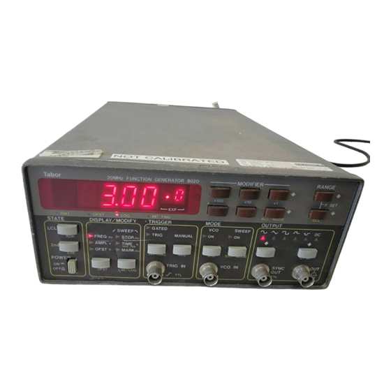
A 2nd function is assigned to this switch. Depressing this push-button after the [2nd] button modifies the numeric The front panel layout of the Model 8020 is shown in Fig- read-out to display the programmed GPIB address. ure 3-1. The front panel is generally divided into three sections: controls, connectors, display and indicators. -
Page 25: Front Panel Controls, Indicators And Connectors
Operating Instructions Model 8020 is doubled. Amplitude control has no effect on the am- modulating signal is applied to the EXT. AM input con- plitude level at the SYNC output connector. nector. The carrier level is specified as percentage of the... -
Page 26: Trigger Mode
Selection of one of the trigger modes is done by depressing one of these buttons. The selected mode is in- dicated by an LED. Model 8020 may be triggered from 2. VCO INPUT - The VCO INPUT connector is used for... -
Page 27: Display And Indicators
3-2-3. Display And Indicators 3-4. POWER-UP PROCEDURE 1. DISPLAY - The function of the numeric display is to The basic procedure of powering up the Model 8020 is indicate the value of the various parameters. The display described below. consists of a 4 digit mantissa and a single digit exponent. -
Page 28: Software Reset
Model 8020 Operating Instructions 8. Following the option message, the instrument pro- are described later in this section. ceeds with displaying the previously selected GPIB pri- mary address. If GPIB option is not installed the instru- 3-5. SOFTWARE RESET ment skips this message. The GPIB address is set by front... -
Page 29: Display Messages
3. Model 8021 is placed in internal triggered mode and the programmed pulse/ramp width is greater than the se- Model 8020 is a product of many years of experience and lected internal trigger period. complete understanding of human engineering require- 4. -
Page 30: Ieee-488 Errors
In general, whenever a GPIB programming attempts to A few front panel push-buttons were assigned a secon- put the model 8020 into an error condition, the function dary function. These functions are printed in yellow be- generator responds in two ways. First by displaying a... -
Page 31: Modifier
Operating Instructions Model 8020 ple, the FREQ dimension is Hz. Display readout of 10.00 nificant digit on the numeric display. Depressing these (exp)+3 tells us that the output waveform is programmed buttons for more than one second modifies this digit con- to have a frequency of 10.00 KHz. -
Page 32: Selecting An Output Waveform
Model 8020 Operating Instructions Table 3-3. Note that the modifier buttons [x1], [x10] and Model 8020 may operate as a function generator, as a [x100] can only modify a parameter within one range. sweep generator and as a voltage controlled oscillator. -
Page 33: Voltage Controlled Oscillator Mode
Operating Instructions Model 8020 SWEEP UP - The function generator, when triggered, 2. Depress the [SWP MODE] push-button in the MODE sweeps from value set by FREQ to value set by STOP. group and observe that one of the following read-outs is Sweep time is determined by TIME. -
Page 34: Am Mode (Model 8022 Only)
Setting-up all parameters in a versatile instrument such the light next to AM illuminates. as the Model 8020 takes some time. The set-up time is longer when a couple of tests are involve and more than 3-13. TRIGGERING THE PULSE GENERATOR one set-up is required. -
Page 35: Recall Set-Ups
OFST light illuminates; indi- cating that the offset mode is now active. Repeating the Model 8020 employs a special recall mode which per- sequence of depressing [2nd] and [OFST] turns the light mits ascending or descending scrolling through a... -
Page 36: Introduction
2. Information necessary to connect the Model adopted by the IEEE (Institute of Electrical and 8020 to the bus and to change the bus address is Electronic Engineering) in 1975 and given the IEEE- contained in paragraphs 4-6 and 4-7. -
Page 37: Ieee-488 Bus Lines
IEEE-488.2 Operation Model 8020 Figure 4-1. IEEE Bus Configuration Any given system can have only one controller time. The listening device will then read this infor- (control may be passed to an appropriate device mation, and the appropriate software is then be used through a special command). -
Page 38: Handshake Lines
Model 8020 IEEE-488.2 Operation Figure 4-2. IEEE Handshake Sequence 2. IFC (Interface Clear) - Setting the IFC line 3. NDAC (Not Data Accepted) - the acceptor true (low) causes the bus to go to a known state. also controls the NDAC line. -
Page 39: Data Lines
The data lines are bi-directional and, as with the remaining bus signal lines, low is true. RL - (Remote-Local Function) - The ability of the Model 8020 to be placed in remote or local modes 4-4. INTERFACE FUNCTION CODES is provided by the RL function. -
Page 40: Hardware Consideration
The simplest possible controlled system comprises Custom cables may be con- a controller and one Model 8020. The controller is structed using the information in Table used to send commands to the instrument, which 4-2. Table 4-2 also lists the contact sends data back to the controller. -
Page 41: Bus Commands
This cycle of the Model 8020. It is stored paragraph briefly describes the purpose of the bus in the non-volatile memory of the... -
Page 42: Universal Multiline Commands
The Model The REN bus line must be true before 8020 will indicate that it is in the remote mode by the instrument will respond to an LLO illuminating its front panel REM indicator. To place command. -
Page 43: Addressed Commands
Al- taneously. Model 8020 will return to the default though GET is considered to be an addressed conditions listed in Tables 3-1 and 4-4 when re- command, many devices respond to GET without sponding to an SDC command. -
Page 44: Unaddress Commands
For example, M2 is sent to the Model 8020 the device will follow when the Group Execute Trigger to place the instrument in the external trigger mode. -
Page 45: Function Element Summary
IEEE-488.2 Operation Model 8020 using the functional syntax diagram and the needs <Arbitrary Block Program Data> A data type of the device. The functional elements include sepa- suitable for sending blocks of arbitrary 8-bit informa- rators, terminators, headers, and data types. These tion. -
Page 46: Program Data Seperator
<Compound Query Program Header> is not No alternative encoding are allowed. Note that IEEE- used in model 8020 and will not be discussed here. P981 amendment forbids the use of CR as a <Pro- A <Common Query Program Header> is defined as: gram Message Terminator>... -
Page 47: Suffix Program Data
4. Generate an SRQ if programmed to do so. The <Non-Decimal Program Data> functional element Device-dependent programming aspects are cov- is not implemented in Model 8020. Therefore it shall ered in paragraph 4-8-5 and 4-10. not be discussed in this manual. - Page 48 Model 8020 IEEE-488.2 Operation Table 4-5. Device-Dependent Command Summary Mode Program Header and Data Description Display VFRQ Frequency VAMP Amplitude VOFS Offset VWID Pulse Width (model 8021) VCAR Carrier Level (model 8022) VSTP Sweep Stop Frequency VSWT Sweep Time VRPT...
- Page 49 Program sweep time NS, US, MS, S Program internal trig. generator per. NS, US, MS, S Program sweep marker HZ, KHZ, MHZ (Model 8020 and 8022 only) DCO Program dc output level MV, V Review Parameters VFRQ Display output frequency...
- Page 50 Model 8020 IEEE-488.2 Operation Table 4-5. Device-Dependent Command Summary (continued) Mode Program Header and Data Description Response Message Format Response header OFF Response header ON New line (LF), END (EOI) terminator New line (LF) terminator END (EOI) terminator No terminator...
-
Page 51: Operating Mode (P,V,A,O)
Program the Model The <command program header> mnemonic is in- 8020 to one of the trigger modes by sending one dependent of control location on the front panel but of the following commands: relates to front panel nomenclature. - Page 52 Operation how the NRf is interpreted by the device. Complete Command/Query Idle State. If the Clear For an example, to program the model 8020 for Status command immediately follows a <Program a frequency output of 10.7 MHz, the following <pro- Message Terminator>, the Output Queue and the...
-
Page 53: Common Commands
IEEE-488.2 Operation Model 8020 store settings in registers designated with numbers 4-11. DEVICE TALKING FORMATS from 00 to 30. This paragraph discusses the formatting of <Response *SRE (Service Request Enable Command) - fol- Message> elements sent from a device via its system lowed by a number, sets the Service Request Enable interface. -
Page 54: Function Element Summary
Model 8020 IEEE-488.2 Operation 4-11-1. Functional Element Summary 4-11-2. Separator Functional Element Summary <Response Message> Represents a sequence The various elements within the <Response Mes- of one or more <Response Message Unit> elements sage> are separated by ASCII characters that were separated by <Response Message Unit Terminator>... -
Page 55: Response Header
Such device-defined que- lence. <Compound Response Header> is not used in model 8020 and will not be discussed here. A ries cause the item read to be removed from the <Common Response Header> is defined as: output queue. -
Page 56: Interrogate Parameter Data Query
8020 (optional common queries 6. The controller sets the ATN line true. that are not included in the model 8020 command 7. The UNT (untalk) command is placed on the set will not be discussed here). -
Page 57: Response Message Terminator
RQS (or MSS) messages. IEEE-488.1 defines to be transmitted. The Model 8020 will normally send the method of reporting the STB and RQS, but EOI during the last byte of its data string or status leaves the setting and clearing protocols and se- word. -
Page 58: Reading The Status Byte Register
The value of the status byte is not altered by a however, in some cases it is not recommended to serial poll. Once the model 8020 has generated an use this method since the entire front panel set-up RQS, its status byte should be read to clear the is reset to factory default values. -
Page 59: Standard Event Status Register (Esr)
Thus, the application programmer can select reasons tively read with the *ESR? common query. The for the model 8020 to issue a ESB summary-message Standard Event Status Register is cleared by a *CLS bit by altering the contents of the ESE Register. -
Page 60: Standard Event Status Register (Ese)
Model 8020 IEEE-488.2 Operation Standard Event Status Register *ESR? Standard Event Status Enable Register *ESE<NRf>, *ESE? Output Queue Not Empty Ramp Error Pulse Error Offset Error read by Serial Poll Service Request Status Byte Register ESB MAV Generation read by *STB? -
Page 61: Machine Status Register (Stt)
Model 8020 is cleared by sending *ESE0. Summary of *ESE 4-15-1. ILI (Illegal Instruction) Error messages is given in the following. An ILI error results when the Model 8020 receives an invalid <Program Header> such as AMPL1.00. *ESE0 - No mask. -
Page 62: Introduction
Table 5-1 as a guide. 5-2. LINE VOLTAGE SELECTION CAUTION The Model 8020 may be operated from either 115 V or 230 Do not use a fuse with a rating higher than V nominal 50- 60 Hz power sources. A special transformer specified or instrument damage may occur. -
Page 63: Option 1 Installation Procedure
Section 4 of this manual. If purchased with the is positioned properly, that pin 1 is connected to pin 1 on Model 8020, the option will be factory installed; however the main board and that no pin on the main board is left the instrument may easily be upgraded in the field by free. -
Page 64: Special Handling Of Static Sensitive Devices
To ensure accuracy, turn on the Clean the exterior of the instrument and the front panel power to the Model 8020 and allow it to warm-up for at with a mild detergent mixed with water, applying the... -
Page 65: Performance Checks Procedure
Squarewave Output Squarewave 2. Set counter to frequency measurment. 2. Set counter to frequency measurment. 3. Set 8020 frequency and verify counter frequency reading 3. Set 8020 frequency and verify counter frequency reading as follows: as follows: 8020 SETTING COUNTER READING... -
Page 66: Amplitude
Model 8020 Maintenance And Performance Tests 5-10-3. Amplitude 3. Set 8020 amplitude and verify DMM amplitude reading as follows: Accuracy specifications (1KHz): +/-2 % of reading from 1.0 V to 15.0 V; +/-4 % of reading from 10 mV to 1.50 V... -
Page 67: Sine Flatness
Connect external 8200 function generator 0dB. to TRIG IN BNC. Check on oscilloscope for 8020 output 4. Change 8020 frequency setting to 10 MHz. signal. 5. Verify that all harmonics are less than -25dB 3. -
Page 68: Vco Control
A noisy Power supply output will 4. Change Sweep type setting to UP and observe that 8020 cause phase modulation in the 8020 output. sweeps up. 5. Connect Sweep Out terminal on the rear panel to the oscilloscope and observe that DC level changes 2V for a full sweep cycle. -
Page 69: Amplitude Modulation (Model 8022)
Maintenance And Performance Tests Model 8020 5-10-12. Amplitude Modulation (model 8022) 2. Connect 8022 output to oscilloscope input. Adjust oscil- loscope vertical gain so that trace height is +/-2 vertical Sensitivity Specifications: 2.5 Vp-p produces 100 % modu- divisions. lation depth when carrier is set to 100 %. -
Page 70: Section 6. Theory Of Operation
This section contains an overall functional description of driving its waveforms into a 50 load. the 8020 series function generators as well as detailed cir- cuit analysis of the various sections of the instruments. In- External gating or triggering effect the current which formation pertaining to the pulse width, the amplitude is supplied to the current generator. -
Page 71: Theory Of Operation
CR8 source, supplies the current to the trigger current source. drives the down current source. The up current source is The trigger current source is doubled and compared with Figure 6-1. Model 8020 - Symplified Block Diagram Page 6-2... -
Page 72: Voltage Controlled Oscillator
Model 8020 Theory Of Operation the down current source. The trigger current source is the feedthrough from the switch drive signal to the range comprised of the Q8 and R19. capacitors. TRIANGLE BUFFER - The triangle buffer includes im- 6-3-2. Voltage Controlled Oscillator pedance converter FET Q19, transistors Q22, 23, 24 and Q25 and their associated components. -
Page 73: Sine Shaper
Theory Of Operation Model 8020 Figure 6-3. VCO Simplified Block Diagram. CAPACITOR MULTIPLIER - The capacitor multi- 6-3-4. Trigger Circuit plier is used for the 2mHz to 19.9Hz ranges. The function of this circuit is to generate an equivalent large capaci- The trigger circuit is active when one of the trigger modes is selected. -
Page 74: Model 8020 - Clamp Circuit Simplified Diagram
Q21 off. This action blocks any signals coming from the trigger input. Figure 6-4. Model 8020 Clamp Circuit Simplified Diagram Figure 6-5. Model 8020 Clamp Circuit Waveforms (Triggered Mode) Page 6-5... -
Page 75: Pulse Shaper
Theory Of Operation Model 8020 Figure 6-6. Model 8020 Clamp Circuit Waveforms (Gated Mode) When the generator is set to operate in Gated mode the positive current generator Q10 and negative current gen- gating signal is routed through U22 to U24. The VCO is erator Q9. -
Page 76: Attenuator
The rest of the circuits are identical to those available on 6-3-9. Power Amplifier the model 8020. Figure 6-8 is a functional block diagram. For complete and detailed schematics, refer to the back of Refer to the schematics at the end of this manual through- this manual. -
Page 77: Pulse Generator Functional Block Diagram
Theory Of Operation Model 8020 The sequence is initiated from a steady state condition where the switching transistor is on. At that time the cur- RANGE CAPACITORS - Serial data from the CPU is rent generator, the range capacitor and the comparator in- converted to parallel information by U30 and U38. -
Page 78: Am Circuit (Model 8022)
A simplified block dia- 8020. Figure 6-9 is a functional block diagram. For com- gram is included for user reference. For more complete plete and detailed schematics, refer to the back of this man- circuit details refer to the digital schematics at the end of ual. -
Page 79: Counter Circuit
U14 is standard IEEE format and is buffered by the two IEEE bus drivers U15 and U16. The bus divers are neces- The counter circuit is employed in the model 8020 for the sary for enhancing the drive capability of the interface. Up purpose of controlling the accuracy of the frequency at the to 15 devices may be connected in parallel. -
Page 80: Section 7. Adjustments
To ensure long-term calibration components and clear the holes to allow a selection of new accuracy, turn on the power to the Model 8020 and allow it to components. warm-up for at least 20 minutes before beginning the adjust- ment procedure. -
Page 81: Adjustment Procedure
Equipment: DMM tical gain of the oscilloscope so that the peak to peak ampli- tude on the screen will be exactly 6 divisions. Change 8020 1. Set DMM to DC measurements. Measure and record the frequency setting to 15.00 MHz. Select C56 and adjust C60 -15 V supply voltage with 10 mV resolution. -
Page 82: Trigger Start Phase Adjustment
1. Change 8020 frequency setting to 1.000 KHz and ampli- tude setting to 1.00 V. 2. Change 8020 Offset setting to 7.00 V and turn offset on. 3. Set DMM to DCV measurements and connect 8020 OUT- PUT, through a 50 ohms feedthrough termination to the DMM. -
Page 83: Triangle Flatness Adjustment
4. Adjust R213 for a peak to peak amplitude of 6 vertical di- 3. Change 8020 Amplitude setting to 15.0 V. visions. 4. Connect 8020 OUTPUT, through a 50 ohms feedthrough termination, to the oscilloscope. 7-3-15. Amplitude Modulation Adjustment (model 8022 5. -
Page 84: Section 8. Parts List
When ordering replacement parts, always include the fol- resistors are 5% 1/4W, resistance is given in ohms, and ca- lowing information: pacitance is given in uF. Table 8-1. Model 8020 Parts List - Main Board Assembly REF DESCRIPTION PART # REF DESCRIPTION... -
Page 85: Parts List
Parts List Model 8020 Table 8-1. Model 8020 Parts List - Main Board Assembly (continued) REF DESCRIPTION PART # REF DESCRIPTION PART # CAP CER .1 -20+80% 50V 1500-01040 TSTR 2N3904A 0400-01200 CAP CER .1 -20+80% 50V 1500-01040 TSTR 2N3904A 0400-01200 CAP CER .1 -20+80% 50V... - Page 86 Model 8020 Parts List Table 8-1. Model 8020 Parts List - Main Board Assembly (continued) REF DESCRIPTION PART # REF DESCRIPTION PART # RES COMP 100K 0100-01040 R107 RES MTF 4.53K 1% 0104-45310 RES MTF 1K 1% 0104-10010 R108 RES COMP 3.9K...
-
Page 87: Model 8020 Parts List - Final Amplifier Board Assembly
Parts List Model 8020 Table 8-1. Model 8020 Parts List - Main Board Assembly (continued) REF DESCRIPTION PART # REF DESCRIPTION PART # R172 RES VAR 2K 3386F 0203-02020 IC 74LS00 0510-00100 R174 RES COMP 1K 0100-01020 IC 74F00 0500-11900... - Page 88 Model 8020 Parts List Table 8-2. Model 8020 Parts List - Final Amplifier Board Assembly (continued) REF DESCRIPTION PART # REF DESCRIPTION PART # CAP POLY.1 20% 100V 1521-01040 TSTR 2N4392A 0400-40000 CAP TANT 10 35V 1540-0106A TSTR J175 0400-02520 CAP POLY.1 20% 100V...
- Page 89 Parts List Model 8020 Table 8-2. Model 8020 Parts List - Final Amplifier Board Assembly (continued) REF DESCRIPTION PART # REF DESCRIPTION PART # RES COMP 100 0100-01010 RES VAR 2K 3386F 0203-02020 RES COMP 4.7K 0100-04720 R100 RES MTF 1K 1%...
- Page 90 Model 8020 Parts List Table 8-3. Model 8021 Parts List - Front Panel Board Assembly REF DESCRIPTION PART # REF DESCRIPTION PART # CAP ELEC 470 16V 1532-04770 DS23 LED RED MV 57124-18 G.I 1000-00700 CAP CER .1 -20%+80% 50V 1500-01040 DS24 LED RED MV 57124-18 G.I...
- Page 91 Parts List Model 8020 Table 8-4. Model 8021 Parts List - Pulse Generator Board Assembly (continued) REF DESCRIPTION PART # REF DESCRIPTION PART # TSTR J109 0400-02500 R206 RES MTF 4.99K 1% 0104-49910 TSTR J109 0400-02500 R207 RES COMP 1K...
- Page 92 Model 8020 Parts List Table 8-5. Model 8022 Parts List - AM Generator Board Assembly (continued) REF DESCRIPTION PART # REF DESCRIPTION PART # R142 RES VAR 100K 3386F-1-104 0203-01040 R161 RES MTF 2.26K 1% 0104-22610 R143 RES MTF 49.9 1%...
- Page 93 Parts List Model 8020 This page was intentionally left blank Page 8-10...
- Page 94 Main Board - Current Generator Main Board - Components Location Keyboard and Display Keyboard and Display - Components Location 8020 Final Amplifier Board - Part 1 8020 Final Amplifier Board - Part 2 9-10 8020 Final Amplifier Board - Components Location...
- Page 111 FREQ Operating Mode Normal Output Squarewave 2. Set counter to frequency measurement. 3. Set 8020 frequency and verify counter frequency reading as follows: 8020 SETTING COUNTER READING 19.99 Hz 19.97 Hz - 20.01 Hz 199.9 Hz 199.7 Hz - 200.1 Hz 1.999 KHz...