Sign In
Upload
Manuals
Brands
SystemAir Manuals
Controller
REPT6
SystemAir REPT6 Manuals
Manuals and User Guides for SystemAir REPT6. We have
1
SystemAir REPT6 manual available for free PDF download: Operating Instructions Manual
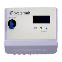
SystemAir REPT6 Operating Instructions Manual (67 pages)
Multipurpose controller for variable voltage 1 ~ fans
Brand:
SystemAir
| Category:
Controller
| Size: 1 MB
Table of Contents
Table of Contents
2
General Notes
5
Structure of the Operating Instructions
5
Target Group
5
Exclusion of Liability
5
Copyright
5
Safety Instructions
5
Intended Use
5
Explanations of Symbols
5
Product Safety
6
Requirements Placed on the Personnel / Due Diligence
6
Start-Up and During Operation
6
Work on the Device
6
Modifications / Interventions in the Device
7
Operator's Obligation of Diligence
7
Employment of External Personnel
7
Product Overview
7
Operational Area
7
Maintenance
7
Transport
7
Storage
8
Disposal / Recycling
8
Mounting
8
General Notes
8
Minimum Space Requirement
8
Outdoor Installation
8
Installation Location for Agriculture
9
Temperature Influences During Commissioning
9
Electrical Installation
9
Safety Precautions
9
EMC-Compatible Installation
9
Motor Cable
9
Signal Cable
9
Harmonics Current for Devices ≤ 16 a
9
Mains Connection
10
Motor Connection
10
Running Noise
10
Motor Protection
10
Signal Connection or Sensor Connection to Analog Inputs (Analog in 1, Analog in 2)
10
Output Voltage 0 - 10 V (Analog Out)
11
Voltage Supply for External Devices (+ 24 V, GND)
11
Add-On Module Type Z-Modul-B Part-No. 380052
11
Digital Inputs (D1, D2)
11
Relay Outputs (K1, K2)
11
Communication
12
Networking Via MODBUS-RTU
12
RS-485 - Network Design and Interface Parameter
12
LON ® Bus System Is Possible Via Add-On Module
13
Potential at Control Voltage Connections
13
Controls and Menu
14
Main Switch
14
Multipurpose LC Display and Keyboard
14
Menu Operation
15
Menu Structure
16
Example for Programming Mode 2.01 in "Base Setup
16
Base Setup
17
Jumper for the Input Signal
17
External Setpoint / External Speed Setting in Manual Operation
17
Select Operation Mode
18
Start-Up
19
Prerequisites for Commissioning
19
Procedure for Commissioning
19
Menu Mode 4.02
19
Programming
20
Speed Controller 1.01
20
Base Setup 1.01
20
Setting for Operation 1.01
20
Menu Speed Controller
21
Temperature Control 2.01
22
Basic Setting 2.01
22
Settings for Operation Modes 2.01
23
Functional Diagrams Temperature Control
24
Additional for Mode
25
Signal Output 0 - 10 V
25
For Mode 2.03 : Relay Output for Heating or Cooling
26
For Mode 2.03 Relay Output for Temperature Monitoring
27
Menu for Temperature Controller 2.01
27
Pressure Control Airconditioning 4.01
29
Base Setup 4.01
29
Setting for Operation Modes 4.01
30
Menu for Pressure Control Airconditioning 4.01
32
Volume Control
33
And
33
Basic Setting
33
Setting for Operation Modes 5.01
33
Menu for Air Volume Control 5.01 and 5.02
35
Air Velocity Control 6.01
36
Base Setup 6.01
36
Settings for Operation Modes 6.01
36
Menu for Air Velocity Control 6.01
37
Menu Group Start
38
Menu Group Info
39
Controller Setup
40
Menu Overview Controller Setup
40
PIN Protection Activate, PIN 0010
40
PIN Protection Activate, PIN 1234
40
Save User Settings Restore with PIN 9090
40
Sensor Alarm on / off
41
Limit
41
Minimum Speed Cut off
41
Second Group
42
Reverse Action of the Control Function
42
Controller Configuration
43
Data on the Total Control Deviation
44
IO Setup
44
Menu Overview "IO Setup
44
Analog-Output "A
45
Digital Inputs "D1" / "D2
46
Menu Overview
46
Enable ON/OFF Function | 1D
46
External Fault Function | 2D
47
Limit on / OFF, Function
47
Switch over Input Signal "E1" / "E2", Function
48
Set 1/2 or Setpoint 1/2, Function
48
Intern / Extern Function | 6D
49
Automatic Control / Speed Manual, Function | 7D
49
Reverse Action of Control Function ( 2.01 ), Function | 8D
50
Reset, Function | 10D
50
Setting Max. Speed on / off Function | 11D
50
Freeze Function" = Maintain Momentary Modulation Value, Function
51
Inverting Analog Inputs "E1" / "E2
51
Function and Inverting for Relay Outputs "K1" and "K2
52
Programming Add-On Module Type Z-Modul-B
53
Networking Via MODBUS
54
Limits
55
Menu Overview "Limits
55
Limit Indication Depending on Modulation
55
Limit Indication Depending on Setting or Sensor Signal
56
Limit Indication Depending on (Offset) to Setpoint
57
Motor Setup
58
Menu "Motorsetup
58
Setting for Rampup Time and Rampdown Time
58
Setting Startvoltage
59
Suppression of Speeds
59
10 Diagnostics Menu
60
11 Events / Fault Signals
61
Display and Query of Events and Malfunctions
61
Messages and Trouble Shooting
62
12 Enclosure
63
Technical Data
63
Performance Reduction During Elevated Ambient Temperatures
63
Connection Diagram
64
Dimensions [MM]
65
Index
66
Manufacturer Reference
67
Advertisement
Advertisement
Related Products
SystemAir RETP6
SystemAir RETP10
SystemAir REP 6
SystemAir REP 10
SystemAir REPT10
SystemAir SYSCROLL AIR RE 40-75
SystemAir RS 60-35 M1 sileo
SystemAir fantech RVF 6XL-EC
SystemAir RS 80-50-100-50 EC
SystemAir RS EC Series
SystemAir Categories
Fan
Air Handlers
Air Conditioner
Ventilation Hood
Fire and Smoke Dampers
More SystemAir Manuals
Login
Sign In
OR
Sign in with Facebook
Sign in with Google
Upload manual
Upload from disk
Upload from URL