Sign In
Upload
Manuals
Brands
Symmetricom Manuals
Measuring Instruments
5071A
Symmetricom 5071A Manuals
Manuals and User Guides for Symmetricom 5071A. We have
2
Symmetricom 5071A manuals available for free PDF download: Assembly And Service Manual, Operating And Programming Manual
Symmetricom 5071A Operating And Programming Manual (194 pages)
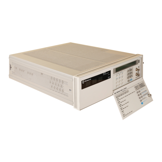
Primary Frequency Standard
Brand:
Symmetricom
| Category:
Laboratory Equipment
| Size: 2 MB
Table of Contents
Safety Considerations
4
Table of Contents
12
Contents
13
Preface
18
Introducing the 5071A
19
Operating the 5071A
21
How this Manual Is Organized
25
Manuals Supplied
26
Related Documentation
26
Accessories, Options, and Specifications
26
Instruments Covered by this Manual
27
Suggested Sequence of Reading
27
Chapter 1 Getting Started
29
Chapter 1 Contents
30
The 5071A at a Glance
31
Indicators
31
Controls
31
Connectors
31
Quick Reference Guide to Controls
31
Rear-Panel Connections
35
Starting the 5071A
36
Performing Basic Tasks
38
Synchronizing to an External 1 PPS Reference
38
Setting Time and Date
39
Powering down the 5071A
39
Chapter 2 Using the 5071A
41
Chapter 2 Contents
42
Using the Front-Panel Menus
44
Keypad Descriptions
44
Controlling the 5071A from the Front-Panel
44
Setting the Output Port Frequency
45
Setting the 1Pps and Clock Outputs
46
To Set the 1Pps Outputs
46
To Synchronize the 1Pps Outputs Using a Time-Interval Counter
46
To Set the Clock
47
To Turn the Clock Display on or off
48
To Schedule a Leap Second
48
Monitoring Status
49
To Select Parameters
49
To Interpret Displayed Results
49
To Print a Status Report
49
Reading and Managing the Event Log
50
To Check Log Status
50
To View Log Entries
50
To Clear the Log
50
To Print the Log
50
Steering the Output Frequency
51
Steering Explained
51
To Add an Offset
51
To Check an Offset
52
To Remove an Offset
52
Using Utility Features
53
To Reset the Continuous Operation Light
53
To Reset the Rear-Panel Status Output
53
To Display the Firmware Revision or CBT Identification String
53
Diagnostic Self-Tests
53
Configuring the 5071A
54
To Set the Operating Mode
54
To Set the Printer Log Mode
54
To Set up the Serial Port
55
To Save a Configuration
55
Connecting a Printer
55
Disabling the Internal Standby Battery
56
Chapter 3 In Case of Difficulty
57
Chapter 3 Contents
58
Front-Panel Indicators and Messages
59
Clock Display
59
Attention Light
59
Continuous Operation Light
59
LCD Display
60
Instrument States
61
Front-Panel Warning Messages
62
Power-Up Problems
63
Using Menus to Check Operational Status
64
Information Menu
64
LOG Menu
64
Utilities Menu
64
CLOCK Menu
64
Configuration Menu
64
Operating System Failure
65
Operating System Failure Symptoms
65
Restarting the 5071A
65
Verifying Operation
66
Cesium Beam Tube Life
66
Chapter 4 Remote Operation and Programming
67
Chapter 4 Contents
68
Remote-Operation Setup
69
Overview
69
Remote Interface Features
69
Serial-Port Description
69
Hardware Connection
70
Serial-Port Configuration
72
Remote-Modem Setup and Precautions
74
Overview
74
Modem Selection
74
Modem Configuration
74
Verifying Remote Operation with a Terminal
75
Programming Overview
76
SCPI Command Conformance
77
Command Types
78
Common Command Format
78
SCPI Command and Query Format
78
RST Reset Response
82
Sample Program Commands
83
Status Monitoring Tasks
84
Instrument Control Tasks
85
Batch Processing for the Program Commands
87
Command Scripts on a Personal Computer
87
SCPI Considerations for HP BASIC
88
Example Program
90
Tips on Using the RS-232C Port on the 5071A
93
Using Ctrl-Q in Programs
95
Setting the Serial Port Parameters with the Option 300 Front Panel
95
Chapter 5 Command Reference
97
Chapter 5 Contents
98
5071A Command Summary
99
IEEE 488.2 Common Commands
99
SCPI Commands
101
Description of SCPI Commands
106
Diagnostic Commands
106
Display Commands
111
Precision Time (Date and Time) Commands
112
Reference Oscillator Commands
116
Status Monitoring Commands
118
System Commands
123
Status Reporting
127
Rear-Panel Status Output Operation
130
Status Output Programming
130
Serial-Port Command/Printer Interface
133
Mode Selection
133
Pacing
133
The Prompt
133
End-Of-Line Characters
133
Error Messages/Codes
134
Chapter 6 Specifications
137
Chapter 6 Contents
138
Accuracy and Stability
139
Frequency Stability (5 and 10 Mhz Outputs)
140
Sinusoidal Output Characteristics (All Located on Rear Panel)
140
Supplemental Characteristics
141
Chapter 7 Installation
145
Chapter 7 Contents
146
Initial Inspection
147
Preparation for Use
148
Power Requirements
148
Selecting Line Voltage and Fuse
149
AC Power Cabling
150
Operating Environment
151
Bench Operation
151
Installing Options 908 and 913
151
Returning the 5071A to Symmetricom
152
Operator's Maintenance
154
Operating the 5071A from External DC Power
154
Preparing the 5071A for External-DC Operation
155
Replacing the External DC Input Power Fuse
156
Internal Standby Battery Maintenance
157
Battery Shelf Life and Storage
157
Battery Operating Temperatures
157
Battery Charging
158
Battery Disposal
159
Removing and Replacing the Internal Battery
160
Cesium Beam Tube Replacement
161
Long-Term Storage
161
Appendix A Performance Tests
163
Introduction
164
Operational Verification
164
Complete Performance Tests
164
RS-232 Verification
164
Test Record
164
Equipment Required
165
5071A Operational Verification
168
Power-On Self-Tests and Servo Lock
168
Rear-Panel Output Signal Checks
170
Required Equipment
170
RS-232 Serial Port Verification
171
5071A Complete Performance Tests
173
Test 1- Output Signals: Harmonic Distortion and Spurious Signals Check
173
Test 2 - Frequency Accuracy
181
Test 3 - Stability
184
5071A Performance Test
185
Appendix B Glossary
187
5071A Glossary
188
Index
191
Service and Support
193
Advertisement
Symmetricom 5071A Assembly And Service Manual (202 pages)
Primary Frequency Standard
Brand:
Symmetricom
| Category:
Measuring Instruments
| Size: 2 MB
Table of Contents
Assembly- Level Service Manual
3
Declares under Our Sole Legal Responsibility that the
10
Declaration of Conformity
10
Table of Contents
11
Contents
12
Preface
15
Repair Strategy
15
Text Conventions Used in this Manual
15
Instrument Identification
15
Instruments Covered by this Manual
16
Manual Organization
16
How to Order Manuals
16
1 Performance Tests - Verifying Specifications
17
Introduction
17
Operational Verification
17
Complete Performance Tests
17
Verification
17
Test Record
18
Equipment Required
18
5071A Operational Verification
21
Power-On Self-Tests and Servo Lock
21
Rear-Panel Output Signal Checks
23
Serial Port Verification
24
5071A Complete Performance Tests
26
Test 1 - Output Signals: Harmonic Distortion and Spurious Signals Check
26
Test 2 - Frequency Accuracy
34
Test 3 - Stability
37
Performance Test Record
38
2 Service
41
Introduction
41
Returning the Instrument to Symmetricom for Service
42
To Provide Repair Information
42
To Pack in the Original Packaging Materials
42
Pre-Troubleshooting Information
43
Safety Considerations
43
Recommended Test Equipment
44
Repair Considerations
44
After Service Considerations
44
Service Accessories
45
Assembly Identification and Location
47
Diagnostic Trees and Procedures
49
5071A Diagnostic Tree Organization
50
Navigating the Diagnostic Trouble-Tree Sections
50
Top-Level Diagnostic Tree Organization
51
Top-Level Diagnostic Tree (Diagnostic Section 1)
53
First Power on
53
DC Input 1 and 2 Power Steering Circuit Check
54
Digital Supply Voltage Check
54
A3 Microprocessor Fault
54
DC-Supply Test/Log-Record Examination
55
Power on Fatal Error Check
56
Instrument Self Tests
56
CBT Warm up
56
Servo-Lock Warning State
57
User-Input/Output Checks
57
5071A Profiling
58
Delayed Failures, Warnings, and Messages
60
Power-On Fatal-Error Diagnostic Tree (Subsection 1)
61
Self Test Diagnostic Tree (Subsection 2)
63
Warm-Up and Fatal Error Diagnostic Tree (Subsection 3)
65
Warning Message Diagnostic Tree (Subsection 4)
73
I/O Diagnostic Tree (Subsection 5)
76
CBT Performance Evaluation (Subsection 6)
77
Advisory Messages (Subsection 7)
81
Functional-Group-Diagnostic Trees (Diagnostic Section 2)
82
Power-Supply Diagnostic Tree (Functional Group Subsection 1)
83
Analog-Signal Chain Diagnostic Tree (Functional-Group Subsection 2)
90
RF-Chain Diagnostic Tree (Functional-Group Subsection 3)
93
C-Field Diagnostic Tree (Functional-Group Subsection 4)
97
Assembly/Module Diagnostic Trees (Diagnostic Section 3)
98
A2 CBT Controller Diagnostic Tree (A/M Subsection 1)
99
A2 Hot-Wire Ionizer Diagnostic Tree
100
A2 Thermistor Diagnostic Tree
102
A2-Mass-Spectrometer Diagnostic Tree
104
A2 Cesium-Oven Diagnostic Tree
106
A5 Diagnostic Tree (A/M Subsection 2)
108
A8 Diagnostic Tree (A/M Subsection 3)
111
A9 Diagnostic Tree (A/M Subsection 4)
115
A10 Diagnostic Tree (A/M Subsection 5)
117
A15 Diagnostic Tree (A/M Subsection 6)
123
A16 Diagnostic Tree (A/M Section 7)
127
A18 Diagnostic Tree (A/M Subsection 8)
132
A19 Diagnostic Tree (A/M Subsection 9)
136
3 Theory of Operation
141
Introduction
141
Basic Operating Principles
141
Simplified Functional Description
142
Functional Block Descriptions
142
A1 Motherboard Circuit Description
142
Simplified Functional Description
143
Instrument Control Block
144
Reference Oscillator/Rf Chain Block
144
Cesium Beam Tube Block
144
Analog Signal Chain Block
145
Input/Output Block
145
Power Supply Block
145
Functional Block Descriptions
146
Instrument Control Block
149
Reference Oscillator/Rf Chain Block
153
Cesium Beam Tube Block
155
Analog Signal Chain Block
157
Input/Output Block
159
Power Supply Block
160
A1 Motherboard Circuit Description
162
A11 Power Steering Logic Assembly
163
Figure 3-8. Opt. 048, Power Supply Block Diagram
172
A12 DC-DC Power Converter Module
174
LF1 AC-Line Filter/Cable Assembly
174
T1 Toroidal Power Transformer
174
B1 Internal-Standby Battery
174
4 Replacing Assemblies - Disassembly and Reassembly
176
Introduction
176
Tools Required
176
Do this First
177
To Remove the Covers
177
To Remove the A2 CBT Control Assembly
178
To Remove any Other PC Boards
178
To Remove A1 Motherboard Assembly
178
To Remove A10 Output Frequency Distribution Amplifier Module
179
To Remove A12 DC-DC Power Converter Module
180
To Remove A13 Front Panel Module
181
To Remove A14 Signal Amplifier Module
182
To Remove A15 9.2 Ghz Microwave Generator Module
183
To Remove A16 High Voltage Supply Module
183
To Remove A17 CBT Assembly
184
Preparation
184
10890A or 10891A CBT Removal
184
CBT Installation
185
Operation Verification
187
Disposal Procedure for Symmetricom Cesium Beam Tubes
188
To Remove A19 Reference Oscillator Module
189
5 Replaceable Parts
190
Introduction
190
Replaceable Parts Table
190
How to Order a Part
190
Parts Identification
190
Contacting Symmetricom
191
6 Specifications
195
Introduction
195
7 Service and Support
196
Index
198
Advertisement
Related Products
Symmetricom 5087B
Symmetricom TimeSource 500
Symmetricom TimeProvider 5000
Symmetricom 5402
Symmetricom 58502A
Symmetricom 59553A
Symmetricom 5120A
Symmetricom 5120A-01
Symmetricom 58503B
Symmetricom 59551A
Symmetricom Categories
Test Equipment
Amplifier
Clock
Receiver
Server
More Symmetricom Manuals
Login
Sign In
OR
Sign in with Facebook
Sign in with Google
Upload manual
Upload from disk
Upload from URL