
Subscribe to Our Youtube Channel
Related Manuals for Symmetricom 5071a


Summary of Contents for Symmetricom 5071a
- Page 1 5071A Primary Frequency Standard Operating and Programming Manual Rev. H, August 14, 2009 Part Number: 05071-90041...
- Page 3 ____________________________________________ Operating and Programming Manual SERIAL NUMBER PREFIX: US4835 (See Instruments Covered by this Manual, in the Introduction for information about manual applicability and your instrument.) Symmetricom 5071A Primary Frequency Standard...
-
Page 4: Safety Considerations
This product is a safety Class I instrument (provided with a protective earth terminal). If this instrument is used in a manner not specified by Symmetricom, the protection provided by the equipment may be impaired. - Page 5 Indicates Alternating current. Indicates Direct current. Rack Mounting The Model 5071A Unit is designed for mounting in a standard 19-inch (48.26 cm) rack. Follow the rack manufacturer's instructions for mounting the Model 5071A Unit while observing the following guidelines: Elevated Operating Temperature: If the Model 5071A Unit is installed in a...
- Page 6 DELA D'UN SIGNE ANNONCIATEUR JUSQU'A CE QUE LES CONDITIONS INDIQUEES SONT ENTIEREMENT COMPRISES ET SONT RENCONTREES. --------------------------------------------------------------------------------------------------------- WARNING: THE MODEL 5071A UNIT SHOULD ONLY BE PLUGGED INTO A GROUNDED RECEPTACLE. SYMMETRICOM RECOMMENDS THAT THE CHASSIS EXTERNAL GROUND BE CONNECTED TO A RELIABLE EARTH GROUND.
- Page 7 Safety Considerations and Warranty Safety Considerations WARNING: FOR CONTINUED PROTECTION AGAINST FIRE, REPLACE THE LINE FUSE(S) ONLY WITH 250V FUSE(S) OF THE SAME CURRENT RATING AND TYPE (FOR EXAMPLE, NORMAL BLOW, TIME DELAY). DO NOT USE REPAIRED FUSES OR SHORT CIRCUITED FUSEHOLDERS. AVERTISSEMENT: POUR LA PROTECTION CONTINUÉE CONTRE LE FEU, REMPLACER LE FUSIBLE DE LIGNE (LES FUSIBLES) SEULEMENT AVEC 250V FUSIBLE...
- Page 8 Safety Considerations and Warranty Safety Considerations (cont’d) DC Power Supply (48 VDC Operation Model) Installation Warning: Ensure that a disconnect device, such as a switch, with the appropriate voltage/current rating is provided when connecting a DC power source to the 48 VDC Operation Model. Avertissement : S'Assurer qu'un débrancher l'appareil, tel qu'un commutateur, avec le classement de tension/courant approprié...
- Page 9 Symmetricom does not warrant that the operation of Symmetricom products will be uninterrupted or error free. If Symmetricom is unable, within a reasonable time, to repair or replace any product to a condition as warranted, the customer would be entitled to a refund of the purchase price upon prompt return of the product.
- Page 10 Safety Considerations and Warranty Warranty (cont’d) Symmetricom will be liable for damage to tangible property per incident up to the greater of $300,000 or the actual amount paid for the product that is the subject of the claim, and for damages for bodily injury or death, to the extent that all such damages are determined by a court of competent jurisdiction to have been directly caused by a defective Symmetricom product.
- Page 11 (Category 9 as defined in Annex 1A of the WEEE 2002/96/EC Directive), which is excluded, from the RoHS Directive 2002/95/EC (reference Article 2, paragraph 1) requirements. Note: The Model 5071A is compliant when supplied with or without the High Performance Option. CE Marking first affixed 2007.
-
Page 12: Table Of Contents
Setting Time and Date ..............11 Powering Down the 5071A ............. 11 Chapter 2 Using the 5071A..........13 Chapter 2 Contents .............14 Using the Front-Panel Menus ..........16 Keypad Descriptions ..............16 Controlling the 5071A From the Front-Panel ....... 16 Operating and Programming Manual... -
Page 13: Contents
To Reset the Rear-Panel Status Output ........25 To Display the Firmware Revision or CBT Identification String . 25 Diagnostic Self-Tests ..............25 Configuring the 5071A............26 To Set the Operating Mode ............26 To Set the Printer Log Mode ............26 To Set Up the Serial Port ............... - Page 14 CLOCK Menu ................. 36 CONFIGuration Menu ..............36 Operating System Failure.............37 Operating System Failure Symptoms ..........37 Restarting the 5071A ..............37 Verifying Operation ..............38 Cesium Beam Tube Life ............38 Chapter 4 Remote Operation and Programming .....39 Chapter 4 Contents .............40 Remote-Operation Setup ............41...
- Page 15 Contents SCPI Considerations For HP BASIC ..........60 Example Program ................62 Tips on Using the RS-232C Port on the 5071A ....65 Using Ctrl-Q in Programs .............. 67 Setting the Serial Port Parameters with the Option 300 Front panel ................67 Chapter 5 Command Reference .........69...
- Page 16 Installing Options 908 and 913 ............ 123 Returning the 5071A to Symmetricom ......124 Operator’s Maintenance ............. 126 Operating the 5071A From External DC Power ....126 Preparing the 5071A For External-DC Operation ...... 127 Replacing the External DC Input Power Fuse ......128 Internal Standby Battery Maintenance ......
- Page 17 Contents RS-232 Serial Port Verification .......... 143 5071A Complete Performance Tests ........145 Test 1— Output Signals: Harmonic Distortion and Spurious Signals Check ................145 Test 2 — Frequency Accuracy ............153 Test 3 — Stability ................. 156 5071A PERFORMANCE TEST............ 157 Appendix B Glossary ............
-
Page 18: Preface
____________________________________________ Preface This preface consists of the following: • Introducing the 5071A page -xvii • Operating The 5071A page -xix • How this Manual is Organized page -xxiii • Manuals Supplied page -xxiv • Related Documentation page -xxiv • Accessories, Options, and Specifications page -xxiv •... -
Page 19: Introducing The 5071A
Starting the 5071A merely requires connecting ac or dc power (see pages 5 and 6). After a typical warm-up time of 15 minutes, the standard is fully operational and the operator may optionally press three keys to display a continuous operation signal. - Page 20 45-minute standby battery (48V option, does not have backup batteries) Accurate and precise output frequency steering Event log As a system component, the 5071A's function is significantly enhanced by its capacity for complete remote control via an RS-232C port on the rear panel. All System...
-
Page 21: Operating The 5071A
Coordinated Universal Time (UTC). See below for more information about the MJD. 1pps outputs: There are three 1pps outputs on the 5071A, one on the front panel and two on the rear panel. All are synchronous (pulses occur at the same time) and isolated from each other so that a short circuit or other disturbance on one, can not effect the amplitude or timing on the others. - Page 22 To ensure proper synchronization of the MJD setting, the clock display must be set to UTC. If the MJD is not set, the 5071A will start with 00000 in its MJD counter, and increment from there each time the clock display passes 00:00:00 hours.
- Page 23 Power-source priority is controlled by the 5071A. The priority order is: 1. AC-line power: when below the specified minimum voltage or if absent, the 5071A switches to, 2. External-dc power: if this fails or goes below 22 Vdc, the 5071A switches to, 3. Internal-Standby battery power.
- Page 24 CAUSE A LOSS OF TIME AND FREQUENCY ACCURACY. (See Cautions beginning on page 25.) 1. Normal mode: The 5071A always powers up in this mode. Use this mode for all normal operation and timekeeping. 2. Standby mode: The Standby mode is enabled through the Utility menu and is used for two special purposes;...
-
Page 25: How This Manual Is Organized
Gives details for installation and maintenance. Appendix A Performance Tests — Provides procedures that verify the 5071A Primary Frequency Standard operate properly and meet electrical performance specifications. Electrical performance is tested against the specifications listed in Chapter 6, ―Specifications,‖ in this manual. -
Page 26: Manuals Supplied
Preface Manuals Supplied Operating and Programming manual (this manual), part number 05071-90041 Related Documentation 1. Beginner's Guide to SCPI: part number - H2325-90001 - Edition July 1990, or Beginner's Guide to SCPI, Barry Eppler, Addison-Wesley Publishing Co. 1991. 2. Standard Commands for Programmable Instruments (SCPI), Version 1991.0, May 1991. -
Page 27: Instruments Covered By This Manual
Complimentary copies of the supplement are available from Symmetricom. For information concerning a serial number prefix that is not listed on the title page or the Manual Updating Changes supplement, contact the nearest Symmetricom Customer Service Center. - Page 28 Preface xxvi Operating and Programming Manual...
-
Page 29: Chapter 1 Getting Started
____________________________________________ Chapter 1 Getting Started Getting Started... -
Page 30: Chapter 1 Contents
Contents This chapter introduces you to the front-panel interface menus and shows how to perform more complex time-keeping tasks. This chapter is organized as follows: • The 5071A at a Glance page 3 • Rear-Panel Connections page 7 • Starting the 5071A page 8 •... -
Page 31: The 5071A At A Glance
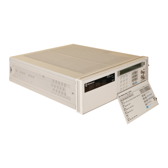
The 5071A at a Glance The 5071A at a Glance If you've unpacked and inspected the 5071A and are ready to operate it, go to the top of page 8. The front-panel features are illustrated and briefly described on the following pages. - Page 32 Chapter 1 Getting Started The 5071A at a Glance Operating and Programming Manual...
- Page 33 Chapter 1 Getting Started The 5071A at a Glance Operating and Programming Manual...
- Page 34 Chapter 1 Getting Started The 5071A at a Glance 48V OPTION REAR PANEL VIEW Operating and Programming Manual...
-
Page 35: Rear-Panel Connections
Chapter 1 Getting Started The 5071A at a Glance Rear-Panel Connections The item numbers in Table 1-1 correspond to the callouts in the adjacent illustration on pages 5 and 6. Table 1-1. Connector Descriptions Item Connector Signal Program Page Number... -
Page 36: Starting The 5071A
Chapter 1 Getting Started Starting the 5071A Starting the 5071A Inspect the instrument for any damage (see page 119 for details). Ensure that the ac-power setting, ac line fuse, (rear panel) and supplied power cord are appropriate for the ac-power source. - Page 37 Chapter 1 Getting Started Starting the 5071A The 5071A will power up at shipment receipt with the following configuration: NOTE Output Ports Port1 5 MHz output Port2 10 MHz output RS-232C Baud rate 2400 Data bits Parity none Stop bits...
-
Page 38: Performing Basic Tasks
• +2 to +10 Volts into 50Ω (TTL Threshold), • Width = 100 ns minimum to 100 µs maximum, Rise time <50 ns. The 1PPS output from a 5061A/B or 5071A meets these sync-pulse requirements. As NOTE an alternative, the 1pps may be manually synchronized (see page 18). -
Page 39: Setting Time And Date
(Note: 48V option does not have internal-standby battery). If the 5071A is used in a system or operation where power is removed on a daily or more repetitive basis, it is strongly recommended that the internal standby batteries be physically disconnected (this step is not required for 48V option instruments). - Page 40 Chapter 1 Getting Started Performing Basic Tasks Operating and Programming Manual...
-
Page 41: Chapter 2 Using The 5071A
____________________________________________ Chapter 2 Using the 5071A Using the 5071A... -
Page 42: Chapter 2 Contents
– Keypad Descriptions page 16 – ACTIONS Keypad page 16 – DATA ENTRY / FUNCTION Keypad page 16 – Controlling the 5071A From the Front-Panel page 16 • Setting the Output Port Frequency page 17 • Setting the 1pps and Clock Outputs page 18 –... - Page 43 Chapter 2 Using the 5071A Chapter Contents • Configuring the 5071A page 26 – To Set the Operating Mode page 26 – To Set the Printer Log Mode page 26 – To Set Up the Serial Port page 27 – To Save a Configuration page 27 •...
-
Page 44: Using The Front-Panel Menus
Refer to page 3 for the available menus, display icons, and conventions. Controlling the 5071A From the Front-Panel You can customize the 5071A’s operation by performing a number of tasks after the instrument is running normally (see page 10). When you’ve completed most of these tasks, no further operator intervention will usually be required. -
Page 45: Setting The Output Port Frequency
Chapter 2 Using the 5071A Setting the Output Port Frequency Setting the Output Port Frequency Use this procedure to set the output frequencies at rear-panel ports 1 and 2 to either 5 or 10 MHz. When the frequency of a port is changed and then returned to the previous NOTE frequency, the original phase is restored. -
Page 46: Setting The 1Pps And Clock Outputs
Connect the reference 1 PPS signal to the START input of the TI counter. Connect the 5071A’s 1pps Output to the STOP input of the TI counter. Set the counter‘s trigger-level controls to trigger on the leading edge of each signal at the 50% amplitude point. -
Page 47: To Set The Clock
During the course of configuring and using the 5071A, you‘ll have occasion to set the date. The 5071A uses the MJD to date log entries as well as tagging the day that a leap second is to be added or subtracted. -
Page 48: To Turn The Clock Display On Or Off
Press to enter the clock display control field. Press the Inc or Dec keys to toggle the display ON or OFF. To Schedule a Leap Second You can pre-program the 5071A to add or subtract a leap second on a designated MJD. Select the CLOCK menu. -
Page 49: Monitoring Status
Chapter 2 Using the 5071A Monitoring Status Monitoring Status Use the following procedures to check the 5071A‘s operational status and selected internal parameters. To Select Parameters Press Shift, then 7 (INFO): display shows instrument status. Select the reading you want to check then use the cursor keys to examine the instrument’s status. -
Page 50: Reading And Managing The Event Log
Chapter 2 Using the 5071A Reading and Managing the Event Log Reading and Managing the Event Log The event log contains a history of such things as power-supply status, errors, and warnings. A maximum of 192 entries can be recorded with each numbered entry time-and-date stamped. -
Page 51: Steering The Output Frequency
Steering the Output Frequency Steering Explained In normal operation, the output frequencies of the 5071A are in fixed relation to the Cesium Beam tube response. This relationship provides the basis for traceability of the 5071A to the international definition of time. -
Page 52: To Check An Offset
Steering the Output Frequency NOTE The steering value is NOT stored in the 5071A non-volatile memory. If the Continuous operation LED is flashing any time after a reset, it indicates that power was lost during operation. This would mean that any steering value you have previously entered is no longer in effect. -
Page 53: Using Utility Features
Chapter 2 Using the 5071A Using Utility Features Using Utility Features Use the following procedures to run selected utility functions. To Reset the Continuous Operation Light Use the following procedure when the Continuous Operation light is flashing. If the Continuous operation LED is flashing any time after a reset, it indicates that NOTE power was lost during operation. -
Page 54: Configuring The 5071A
When you put the 5071A into Standby mode, the Cesium Beam tube is shut-down CAUTION except for the Ion pump. The 5071A will not maintain accurate time or frequency in this mode. Placing the instrument back into Normal mode initiates the normal CBT power-up sequence. -
Page 55: To Set Up The Serial Port
Connecting a Printer You can connect a printer to the 5071A to create hardcopy output of the internal event log entries or print current status. Refer to Chapter 4, ―Remote Operation and Programming,‖ in this manual to connect and configure a serial printer to the instrument‘s RS-232C port. -
Page 56: Disabling The Internal Standby Battery
(Refer to Chapter 7, ―Internal Standby Battery Maintenance‖ and ―Battery Charging,‖ for more information.) If your situation requires you to operate the 5071A under these conditions, it is strongly recommended that the internal batteries be manually disconnected each time power is removed, or permanently disconnected. This will ensure that the batteries are not stressed by continual under-charging. -
Page 57: Chapter 3 In Case Of Difficulty
____________________________________________ Chapter 3 In Case of Difficulty In Case of Difficulty... -
Page 58: Chapter 3 Contents
– CONFIGuration Menu page 36 • Operating System Failure page 37 – Operating System Failure Symptoms page 37 – Restarting the 5071A page 37 • Verifying Operation page 38 • Cesium Beam Tube Life page 38 Operating and Programming Manual... -
Page 59: Front-Panel Indicators And Messages
All references to internal-battery power, battery status or battery operation, do Note not apply for 5071A 48V option. You can use the front-panel indications and messages to assess the instrument‘s operation and status. The warning messages that can appear on the front panel LCD are listed and explained on the next two pages. -
Page 60: Lcd Display
Chapter 3 In Case of Difficulty Front-Panel Indicators and Messages LCD Display Consists of two 40-character lines that can show you: • Active functions and menus • Active operating settings • Available menu choices and options • Internal operating parameters •... -
Page 61: Instrument States
If the internal battery became exhausted while attempting to sustain operation, it cannot be assumed that it is completely re-charged until the 5071A has been connected to ac mains for at least 16 hours. -
Page 62: Front-Panel Warning Messages
Chapter 3 In Case of Difficulty Front-Panel Indicators and Messages Front-Panel Warning Messages If you attempt an operation that isn‘t allowed, the 5071A will make an audible beep and display one of three possible warning messages: Remote Mode The LCD display shows the small padlock symbol at the far right-hand side of the screen. -
Page 63: Power-Up Problems
4. If the fuse blows again, disconnect power immediately and contact the nearest Symmetricom Customer Service Center for assistance. • If you attempt to start the 5071A when its temperature is below 0˚ Centigrade, the allotted maximum 45-minute power-up/warm-up time may not be sufficient to heat both the Cesium Beam tube oven and VCXO oven. -
Page 64: Using Menus To Check Operational Status
Using Menus to Check Operational Status Using Menus to Check Operational Status This section provides suggested ways to use the menus for checking the operational status of the 5071A. A specific procedure for each menu is provided in Chapter 2, ―Using the 5071A.‖ INFOrmation Menu Use the INFO (Information) menu to check: •... -
Page 65: Operating System Failure
Operating System Failure This section provides information to check symptoms associated with operating system failures and a procedure to restart the 5071A in the event of such a failure. Operating System Failure Symptoms Five symptoms are associated with operating system failure: •... -
Page 66: Verifying Operation
Verifying Operation Verifying Operation Perform the Operational Verification starting on page 136 of Appendix A, ―Performance Tests,‖ to verify that the 5071A is operating properly. Cesium Beam Tube Life This section provides information to check the Long-Term operating status of the instrument‘s Cesium Beam tube. -
Page 67: Chapter 4 Remote Operation And Programming
____________________________________________ Chapter 4 Remote Operation and Programming Remote Operation and Programming... -
Page 68: Chapter 4 Contents
Chapter 4 Remote Operation and Programming Chapter 4 Contents Chapter 4 Contents This chapter gives you the information required to set up and operate the 5071A as a remote device. This chapter is organized as follows: • Remote-Operation Setup page 41 –... -
Page 69: Remote-Operation Setup
Programming Overview section in this chapter and command reference information in Chapter 5. Serial-Port Description The 5071A‘s serial port is a DTE device that may be connected to a printer, terminal, computer, or modem. The available transmission protocol features are: •... -
Page 70: Hardware Connection
The rear-panel serial-port connection uses a 9-pin Male, D-Subminiature connector. Signal voltage levels comply with the RS-232C standard. The serial- port connections are electrically isolated from the 5071A‘s ground and circuitry. The serial port pin assignments are listed below: Function... - Page 71 Chapter 4 Remote Operation and Programming Remote-Operation Setup Figure 4-1. RS-232C Cabling Setups Operating and Programming Manual...
-
Page 72: Serial-Port Configuration
The COM1 (or COM2) Properties dialog box is displayed. This dialog box allows you to configure the RS-232 port of the PC. Set the RS-232 port of the PC to match the default values of the 5071A. Once you‘ve enabled the correct COM port from the PC, a prompt should appear each time you press the enter (or return) key. - Page 73 > *idn? SYMMETRICOM,5071A,US48051234, 4805 scpi > After you‘ve selected the communication parameters for the terminal, be sure to configure the 5071A‘s serial port with the same values, using the CONFIG menu‘s Serial option. Operating and Programming Manual...
-
Page 74: Remote-Modem Setup And Precautions
The modem used to control the 5071A must be capable of operating without hardware handshake and should be connected to provide an asserted DSR signal to the 5071A. The pin-out of the 9-pin serial connector on the rear panel of the 5071A is listed at the beginning of this chapter. -
Page 75: Verifying Remote Operation With A Terminal
Remote-Modem Setup and Precautions Under these conditions, the communication-path configuration is handled by the calling computer or terminal, and the link to the 5071A works as it would for a direct RS-232C connection. The calling computer and 5071A must be set to the same Baud rate at the outset. -
Page 76: Programming Overview
5071A‘s programming command format, syntax, and *RST response (initialization state). After reading this section you will have a basic knowledge of how to use and understand the SCPI commands for the 5071A Primary Frequency Standard. The details of the 5071A‘s SCPI and IEEE Common Commands appear in the... -
Page 77: Scpi Command Conformance
Chapter 4 Remote Operation and Programming SCPI Command Conformance SCPI Command Conformance The SCPI commands used in the 5071A are in conformance with the SCPI Standard Version 1990.0. The instruments SCPI command set consists of the following: • Common Commands as defined in IEEE 488.2 - 1987. -
Page 78: Command Types
Chapter 4 Remote Operation and Programming Command Types Command Types There are two types of 5071A program commands: IEEE 488.2 Common and SCPI. The SCPI commands control instrument functions while the IEEE 488.2 Common commands control and manage communications between the 5071A and a terminal or personal computer. - Page 79 Upper case letters indicate the abbreviated spelling for the command. For shorter program lines, send the abbreviated form. For better program readability, you may send the entire command. The 5071A accepts either command form and is not case sensitive.
- Page 80 Chapter 4 Remote Operation and Programming Command Types If a command is an implied form but can also accept channel numbers, the implied form pertains to channel 1 only. To switch channels, you must use the channel number in the command string. For example: ROSC:FREQ2 5E6 Parameter Types Table 4-1 contains explanations and examples of parameter and response types...
- Page 81 Chapter 4 Remote Operation and Programming Command Types Optional Parameters Parameters shown within square brackets ([ ]) are optional parameters. (The brackets are not part of the parameter and are not sent to the instrument.) If you do not specify a value for an optional parameter, the instrument selects the most appropriate value.
-
Page 82: Rst Reset Response
SYST:DIAG:CONT:RESET and will generate an error. *RST Reset Response The 5071A reset response (Initialization state) is the configuration acquired at program reset. Table 4-2 summarizes this state. Once a configuration has been saved, it will persist even if power is removed or until it is reprogrammed (via SCPI commands or through the front-panel menus). -
Page 83: Sample Program Commands
SCPI Command Tree/Summary in Chapter 5 of this manual. A complete list of 5071A error messages including code numbers and causes is located at the end of Chapter 5. -
Page 84: Status Monitoring Tasks
Status Monitoring Tasks Example Program 1 — Status Report Inquiry The commands you send are in BOLD, (followed by <CR><LF>) the 5071A‘s responses are in italics. If you make a mistake (i.e., generate an error # at the scpi prompt) type ―*cls‖ followed by <CR><LF> (Return Line Feed). -
Page 85: Instrument Control Tasks
Sample Program Commands Instrument Control Tasks The commands you send are in BOLD, (followed by <CR><LF>) the 5071A‘s responses are in italics. If you make a mistake (i.e., generate an error # at the scpi prompt) type *cls followed by <CR><LF>. - Page 86 Chapter 5 Command Reference Sample Program Commands Example Program 3 — Leap Second Insertion Program Dialog Task Function SOUR:PTIM:LEAP:MJD 48621 Set date of leap second. scpi > SOUR:PTIM:LEAP:DUR 59 Set time (show minute). scpi > SOUR:PTIM:LEAP ON Enable Leap second insertion. scpi >...
-
Page 87: Batch Processing For The Program Commands
Chapter 4 Remote Operation and Programming Batch Processing for the Program Commands Batch Processing for the Program Commands This section provides information for automating the sample program commands presented in the previous section. HP/Agilent‘s AdvanceLink for Windows data communications program for the personal computer is discussed first. This is followed by some important considerations for using SCPI commands with HP BASIC on the HP 9000 Series 200/300 instrument controllers. -
Page 88: Scpi Considerations For Hp Basic
More details of the serial protocol can be found in Chapter 5, ―Serial-Port Command/Printer Interface.‖ An IEEE-488.2 to RS232 converter can also be used to drive the 5071A from an IEEE-488.2 interface. The converter must provide buffering for the incoming serial data since the serial port of the 5071A uses full-duplex operation. - Page 89 Batch Processing for the Program Commands Printer-Mode Output If you want to monitor instrument operation with a printer, the 5071A has an operating mode that automatically sends operational or warning messages out the serial port to a printer (or terminal).
-
Page 90: Example Program
22 PRINT Return$ 23 ! 24 ASSIGN @Ser_in TO Com_port;FORMAT ON 25 ASSIGN @Ser_out TO Com_port;FORMAT ON 26 ! 27 !----------------------------------------------------------------------- 28 ! Command and Query 5071A. 29 ! 30 Return$=FNTalker$("*CLS") ! Clear status registers and 31 PRINT Return$ ! error queue. - Page 91 ! code. ! The configuration is 8 data-bits, 1 stop-bit, and no parity. ! The 5071a requires the interface to assert the DTR line, or to ! leave it un-connected. There is no hardware handshake. ! The returned string reports the details of the set-up.
- Page 92 125 ! Program Output The program output is shown below. Notice that the 5071A echoes the commands or queries it receives. After echoing a command, it returns a prompt. After echoing a query, it returns the result of the query and a prompt.
-
Page 93: Tips On Using The Rs-232C Port On The 5071A
If this is not the case, the 5071A front panel can appear to be frozen (no key presses accepted) if it is communicating with another serial device via the RS- 232C and receives a data holdoff from that device. - Page 94 If the printer uses the XON/XOFF protocol, it will send an XOFF (Control-S) that will stop the flow of data from the 5071A. The front panel is now busy waiting for an XON (Control-Q) to resume printing.
-
Page 95: Using Ctrl-Q In Programs
The program "5071ASerialConfig " can be used to determine the current serial port configuration and to change it to your specific needs. When shipped from the factory a standard 5071A is set to 2400,N,8,1. It is also possible to change the configuration using this software. - Page 96 Chapter 4 Remote Operation and Programming Tips on Using the RS-232C Port on the 5071A Use the software in any PC with an RS-232 (COM) port connected to the 5071A as described in this manual. If you cannot locate the CD or need a copy of the program, you can download it from our website at http://www.Symmetricom.com...
-
Page 97: Chapter 5 Command Reference
____________________________________________ Chapter 5 Command Reference Command Reference... -
Page 98: Chapter 5 Contents
Chapter 5 Contents Chapter 5 Contents This chapter describes the SCPI and IEEE 488.2 commands and error messages applicable to the 5071A Primary Frequency Standard. Software interface and status reporting operation are also discussed. The chapter is organized as follows: •... -
Page 99: 5071A Command Summary
Table 5-2 as New. The IEEE 488.2 commands are summarized first (Table 5-1) followed by SCPI commands (Table 5-2). Details of all 5071A SCPI commands can be found in the SCPI Subsystem Commands section following the SCPI Command summary. - Page 100 Chapter 5 Command Reference 5071A Command Summary Table 5-1. IEEE 488.2 Common Commands Mnemonic Command Name Function *CLS Clear Status Clears the status registers and error queue *ESE Standard Event Status Enable Sets the Standard Event Status Enable Register bits...
-
Page 101: Scpi Commands
Chapter 5 Command Reference 5071A Command Summary SCPI Commands Table 5-2 lists SCPI commands by keyword, syntax, parameter and response form and provides brief explanatory comments. Table 5-2. SCPI Command Summary Command Parameter Form Response Form Comment DIAGNOSTIC COMMANDS DIAGnostic:CBTSerial? <string>... - Page 102 Chapter 5 Command Reference 5071A Command Summary Table 5-2. SCPI Command Summary (Continued) Command Parameter Form Response Form Comment DIAGnostic :VOLTage:HWIonizer? <NR3> Returns Hot wire ionizer Volts. DIAGnostic :VOLTage:MSPec? <NR3> Returns Mass spectrometer Volts. DIAGnostic :VOLTage:PLLoop? <NR3,NR3, Returns Phase-Lock Loop Volts.
- Page 103 Chapter 5 Command Reference 5071A Command Summary Table 5-2. SCPI Command Summary (Continued) Command Parameter Form Response Form Comment [SOURce]:PTIMe:STANdby <OFF|0|ON|1> Sets/resets Standby mode. [SOURce]:PTIMe:STANdby? <0|1> Returns Standby mode status. [SOURce]:PTIMe:SYNChronization <OFF|FRONt| Arms selected Sync port. REAR> [SOURce]:PTIMe:SYNChronization? <OFF|FRON| Returns armed Sync port, if any.
- Page 104 Chapter 5 Command Reference 5071A Command Summary Table 5-2. SCPI Command Summary (Continued) Command Parameter Form Response Form Comment STATus:QUEStionable[:EVENt]? <NR1> Returns/clears QEReg contents. STATus:QUEStionable:CONDition? <NR1> Returns QCReg contents. STATus:QUEStionable:ENABle <numeric_value> Sets QEReg to specified value. STATus:QUEStionable:ENABle? <NR1> Returns QEReg contents.
- Page 105 Chapter 5 Command Reference 5071A Command Summary Table 5-2. SCPI Command Summary (Continued) Command Parameter Form Response Form Comment SYSTem:COMMunicate:SERial:BAUD <numeric value> Sets baud rate. 9600, 4800, 2400, 1200, 600, 300 SYSTem:COMMunicate:SERial:BITS <numeric value> Sets number of 7 or 8 data bits.
-
Page 106: Description Of Scpi Commands
DIAGnostic:CONTinuous:RESet This command resets the Continuous Operation light (illuminates continuously) if the instrument has triggered its warning mode. The 5071A must be in REMote mode to execute this command. If DIAG:CONT? is OFF, sending :CONT:RESet will generate error +202, ―Valid only when operating normally‖. - Page 107 Response format = <NR3>, precision = 1 x 10 DIAGnostic:LOG:CLEar This command purges all event log entries. The 5071A must be in REMote mode to execute this command. This command is not affected by *RST and does not have a query. DIAGnostic:LOG :COUNt? This query returns the number of entries in the log as an integer.
- Page 108 DIAGnostic:LOG:VERBosity DISable|TERSe|VERBose|SERVice This command specifies the log stream events actually sent to the serial port. The 5071A must be in REMote mode to execute this command. The following four parameters of the DIAGnostic:LOG:VERBosity command allow you to select the log stream events that will be sent to the serial port: •...
- Page 109 DIAGnostic:TEST? <numeric_value> This query executes the diagnostic test specified by the supplied parameter. The 5071A must be in Standby mode or Fatal error state to successfully execute this command, otherwise error message +203 ―Valid only in standby‖ returns. Response format = <boolean> (0: tests passed, or 1: tests failed).
- Page 110 Chapter 5 Command Reference Description of SCPI Commands DIAGnostic :VOLTage:COVen? This query returns the Cesium oven heater voltage. Response format = <NR3>, precision = 0.1 V. DIAGnostic :VOLTage :EMULtiplier? :This query returns the electron multiplier voltage setpoint. Response format = <NR3>, precision = 1 V. DIAGnostic :VOLTage:HWIonizer? This query returns the hot wire ionizer voltage setpoint.
-
Page 111: Display Commands
This command enables or disables the LED clock display. The display will illuminate if the time has been set. The 5071A must be in REMote mode to execute this command. REMote mode can be set ON by sending *RST. The available parameters are: OFF|0 - turns the display OFF, or ON|1 - turns the display ON. -
Page 112: Precision Time (Date And Time) Commands
Synchronizing 1pps outputs PTIMe[:TIME] <hour>,<minute>,<second> This command sets time in 24-hour format (SCPI standard). The 5071A must be in REMote mode to execute this command. Requires three parameters: hours, minute, and second. Entered values are rounded to integer. The maximum range limits are 23, 59, 59, respectively. - Page 113 Chapter 5 Command Reference Description of SCPI Commands PTIMe:MJDate? [MIN|MAX] This query returns the instrument‘s current MJD. If not set, the date starts at zero and increments at the instrument‘s transition for midnight. Response format = <NR1>. PTIMe:LEAPsecond:DURation <numeric_value> This command programs the length of the minute preceding a scheduled leap second.
- Page 114 PTIMe:SLEW <numeric_value> This command adjusts the epoch of the clock with the supplied parameter. The 5071A must be in REMote mode to execute this command. One parameter is required, accepts ―S‖ suffix. Parameter range = -0.5 S to 0.5 S., precision = 50 ns.
- Page 115 Returns 1 if in standby, 0 if not in standby. PTIMe:SYNChronization OFF|FRONt|REAR This command arms the specified sync port with the supplied parameter. The 5071A must be in REMote mode to execute this command. Arming terminates when: • canceled from the command interface, •...
-
Page 116: Reference Oscillator Commands
Chapter 5 Command Reference Description of SCPI Commands Reference Oscillator Commands The [SOURce]:ROSCillator commands provides more advanced time keeping functions for the 5071A. These functions increase the flexibility of the 5071A by providing a means of: • setting reference oscillator tuning voltage, •... - Page 117 ROSC:FREQuency[1|2] <frequency> This command sets the output frequency of the indicated port with the supplied parameter. The 5071A must be in REMote mode to execute this command. The frequency parameter is 5 x 10 or 10 x 10 Values are rounded to the nearest valid setting, unless out of range.
-
Page 118: Status Monitoring Commands
Chapter 5 Command Reference Description of SCPI Commands STATus Monitoring Commands The STATus commands allow you to examine the status of the instrument by monitoring the Operation Status register and the Questionable Data register. Figure 5-1 shows all of the instrument‘s status registers. The STATus system contains four registers (and the Output Queue), two of which are under IEEE 488.2 control. - Page 119 Chapter 5 Command Reference Description of SCPI Commands Operating and Programming Manual...
- Page 120 Chapter 5 Command Reference Description of SCPI Commands STATus:OPERation[:EVENt]? This query returns the contents of the OPERation event register, then clears the event register. The event register bits are determined by the settings of the corresponding rise, fall, and condition registers. Response format = <NR1>.
- Page 121 Using the Questionable Data Register The Questionable Data Register conveys information about the quality of the instrument‘s functions and outputs. The 5071A implements bits 2, 5, and 6 of the Questionable Data Register. (Refer to the Status Reporting section of this chapter for more details.)
- Page 122 Chapter 5 Command Reference Description of SCPI Commands STATus:QUEStionable:ENABle? This query reports the contents of the QUEStionable enable register, non destructively. Response format = <NR1> STATus:QUEStionable:NTRansition <numeric_value> This command sets the negative transition filter (fall register) as specified. Meaningful values are in the range 0 to 32767. STATus:QUEStionable:NTRansition? This query reports the contents of the fall register.
-
Page 123: System Commands
Chapter 5 Command Reference Description of SCPI Commands System Commands The SYSTem commands control functions related to remote system communication, configuration, and any error messages. Any commands which alter the state of the instrument will return error +201 if NOTE the instrument is not in REMOTE mode when the command is issued. - Page 124 Chapter 5 Command Reference Description of SCPI Commands SYSTem:KEY <numeric_value> This command inserts the specified keycode into the keypress queue. Operates with remote OFF. Input range: 0 to 19, 128 to 149. Code 148 turns the SHIFT annunciator On, while code 0 turns it Off. Codes 1 - 19 point to unshifted keys in left-right, top-bottom order.
- Page 125 • Output port frequencies • Printer report level The 5071A must be in REMote mode to execute this command. The function of this command is not affected by *RST. SYSTem:TIME <hours>,<minutes>,<seconds> This command is equivalent to ―SOUR:PTIM:TIME‖. The function of this command is not affected by *RST.
- Page 126 Chapter 5 Command Reference Description of SCPI Commands SYSTem:VERSion? This query returns the SCPI version number for which the instrument complies (1990.0). Response format = <NR2>. SYSTem:COMMunicate:SERial:BAUD <numeric_value> This command sets RS-232C baud rate. Input values: 300, 600, 1200, 2400, 4800, 9600. SYSTem:COMMunicate:SERial:BITS <numeric_value>...
-
Page 127: Status Reporting
Chapter 5 Command Reference Status Reporting Status Reporting The 5071A status registers conform to the SCPI and IEEE 488.2 standards applicable with an RS-232C serial data-communications port. RS-232C does not support serial poll, parallel poll, or SRQ. Instead, IEEE SRQ and RQS signals will always have the same state, and will be reflected in the state of the (low TRUE) status output port (rear-panel Status Output BNC connector). - Page 128 Chapter 5 Command Reference Status Reporting Table 5-4. IEEE Standard Event Status Register (ESR) Function Name OPC IEEE Operation complete RQC (not used) SCPI Query error SCPI Device Dependent Error SCPI Execution Error SCPI Command Error URQ (not used) PON Power On flag Table 5-5.
- Page 129 Chapter 5 Command Reference Status Reporting Table 5-6. SCPI QUEStionable Status Register Function Name Bit Status VOLTage always zero CURRent always zero TIME Condition cleared when clock is set. POWer always zero TEMPerature always zero FREQuency Indicates out-of-lock condition (see log) PHASe Indicates spurious bursts from servo chain MODulation...
-
Page 130: Rear-Panel Status Output Operation
After successful power-on and warm up, the 5071A will assert its status output active when the instrument leaves normal operation. This exit from normal operation may be programmed for a variety of conditions. Two example conditions are described below. - Page 131 Example 2 — Programming the Status Output for Multiple True and False Conditions This example describes how to program the Status Output to go active when the 5071A encounters any combination of the following transitional conditions: • CALibrating - true bit = 1 •...
- Page 132 Chapter 5 Command Reference Rear-Panel Status Output Operation 3. By adding all the false condition bit values (in this case, only one) we get the value 1024 which is used to program the STAT:OPER:NTR command. The resulting SCPI command entries are: •...
-
Page 133: Serial-Port Command/Printer Interface
End-Of-Line Characters The 5071A will receive lines terminated with CR (ASCII 13 decimal), LF (ASCII 10 decimal), or one followed immediately by the other, in either order. There is no support for IEEE 488 <EOI>. The instrument always terminates formatted output lines with <CR>... -
Page 134: Error Messages/Codes
Table 5-7 lists and describes the error messages. Table 5-7. Error Messages Number Error String Cause -100 Command error This is the generic syntax error used if the 5071A cannot detect more specific errors. -101 Invalid character Unrecognized character in specified parameter. -102 Syntax error Command missing space/comma between parameters. - Page 135 Chapter 5 Command Reference Error Messages/Codes Table 5-7. Error Messages (Continued) Number Error String Cause -161 Invalid block data Entered block data syntax invalid. -168 Block data not allowed Block data encountered but was not allowed. -170 Expression error Entered expression contained a non-specific error. -171 Invalid expression Entered block data syntax invalid.
- Page 136 Chapter 5 Command Reference Error Messages/Codes Operating and Programming Manual...
-
Page 137: Chapter 6 Specifications
____________________________________________ Chapter 6 Specifications Specifications... -
Page 138: Chapter 6 Contents
Chapter 6 Contents Chapter 6 Contents This chapter provides the technical specifications for the 5071A. Specifications describe the instrument's warranted performance. Supplemental characteristics are intended to provide information useful to apply the instrument by giving typical or nominal, but non-warranted performance parameters. -
Page 139: Accuracy And Stability
Chapter 6 Specifications Accuracy and Stability Accuracy and Stability Conditions: Any combination of: Temperature: 0 to 50˚C Humidity: 0 to 80% (40˚C maximum) Magnetic Field: dc, 55, 60 Hz; 0 to 0.2 millitesla (2 Gauss) peak — any orientation Pressure: 47 kPa (equivalent to an altitude of 6 km) Shock Vibration: 100-mm drop Standard High-performance... -
Page 140: Frequency Stability (5 And 10 Mhz Outputs)
Chapter 6 Specifications Frequency Stability Frequency stability (5 and 10 MHz outputs) Time Domain Stability † Frequency Domain Stability † SSB Phase Noise† dBc (2, )† Offset from Averaging Signal (Hz) Standard High-Perf. 10 MHz 5 MHz Time Cesium Cesium Output Output* Beam Tube... -
Page 141: Supplemental Characteristics
Automatic synchronization: Input power (nominal): isolated and floating with to within 50 ns of reference AC: Primary power source; respect to 5071A chassis. pulse. unit will draw AC power in Software command set: Sync pulse: 2 inputs; each may be preference to DC power. - Page 142 MIL-STD-461 C, Part 7, Class B. communication and control of on the electronics (the cesium dc magnetic field: up to the 5071A is done via the rear- beam tube is warranted 7.8 Gauss. panel RS-232 (serial) port. separately). This option adds to...
- Page 143 In the 5071A, both Port 1 and Port 2 high (TIA) monitored by the BIH (Bureau International isolation output frequencies are derived from the L'Heure) in Paris, France.
- Page 144 (2, ) where y is the standard deviation, 2 means that measurements are taken in pairs, and is the measurement time. In the 5071A specifications, values for all averaging times are shown in one chart for convenience. However, short-term stability...
-
Page 145: Chapter 7 Installation
____________________________________________ Chapter 7 Installation Installation... -
Page 146: Chapter 7 Contents
Chapter 7 Installation Chapter 7 Contents Chapter 7 Contents This chapter provides information to inspect, install, commission, and maintain the 5071A Primary Frequency Standard. Installation information is also provided for external-DC operation and rack mounting. The chapter is organized as follows: •... -
Page 147: Initial Inspection
• If the shipping container is damaged, or the cushioning material shows signs of stress, notify the carrier as well as the Symmetricom office. Keep the shipping materials for the carrier’s inspection. The Symmetricom office will arrange for repair or replacement at Symmetricom’s option without waiting for a claim settlement. -
Page 148: Preparation For Use
How to return the instrument to Symmetricom. Power Requirements The 5071A can operate from ac power sources of 100-, 120-, 220-, or 240 volts ac, 45 to 66 Hertz for all voltages, 400 (10%) Hertz for 100-, and 120-volts AC. -
Page 149: Selecting Line Voltage And Fuse
100-, 120-, 220-, or 240 volt ac-operation as shown in Figure 7-1. Before applying ac power to the 5071A, the turret wheel selector must be set to the correct position and the correct fuse must be installed as described in the following paragraphs. -
Page 150: Ac Power Cabling
Chapter 7 Installation Preparation for Use AC Power Cabling This instrument is equipped with a three-wire power cable. When connected to an appropriate ac-power receptacle, this cable grounds the instrument cabinet. The type of power cable shipped with each instrument depends on the country of destination. Table 7-1 lists the part number of the power cables and the available mains plugs. -
Page 151: Operating Environment
Chapter 7 Installation Preparation for Use Operating Environment The 5071A may be operated in temperatures from 0 to 55˚ C. Refer to the environmental specifications in chapter 6 for more detailed information. Bench Operation The instrument has plastic feet for convenience in bench operation. -
Page 152: Returning The 5071A To Symmetricom
After you‘ve finished packing the instrument in the inner corrugated carton, refer to the 5071A shipping web site for any other labeling or markings instructions. Overpack may not be required in some areas. The web site is http://www.symmttm.com/5071A/Shipping/... - Page 153 Returning the 5071A to Symmetricom Figure 7-2. 5071A Packing Exploded View Note: Due to changes in packaging regulations, some of the material in the figure above may not be required. Consult the 5071A shipping instructions on http://www.symmttm.com/5071A/Shipping/ for complete information.
-
Page 154: Operator's Maintenance
“Specifications,” on page 113. DC-power connections are made through the rear panel “Ext DC Input” connector. The 5071A runs from ac power when both ac and dc power are WARNING available. The 5071A will not run from dc power unless the ac power source fails or is disconnected. -
Page 155: Preparing The 5071A For External-Dc Operation
Preparing the 5071A For External-DC Operation Use the dc-power connector (supplied) that mates with the Ext DC Input connector on the rear panel, to connect dc power to the 5071A. Follow the procedure below to set up and verify operation from... -
Page 156: Replacing The External Dc Input Power Fuse
Operator’s Maintenance Replacing the External DC Input Power Fuse Remove all power from the 5071A. Press down on the top edge of the dc FUSE cap located under the Ext DC Input connector, then grasp the top and bottom of the fuse holder and gently pull it out (back and slightly down). -
Page 157: Internal Standby Battery Maintenance
The battery pack(s) is designed for use between -40 and +65 C. At 25 C, the 5071A is specified to operate for at least 45 minutes. At 0 C, the 5071A will typically operate for approximately 50 minutes. At 55 C, the instrument operates between 60 and 75 minutes. -
Page 158: Battery Charging
This makes lead-acid the ideal choice for typical constant operating installations of the 5071A. They will last much longer in a full-charge state and provide more reliable capacity when they are needed. -
Page 159: Battery Disposal
CONNECT TOGETHER OR OTHERWISE SHORT-CIRCUIT THE BATTERY TERMINALS; THE PACKS MAY MELT OR CAUSE SERIOUS BURNS. The 5071A should NOT be operated in a gas-tight enclosure, to CAUTION minimize the possibility of any hazardous accumulation of hydrogen gas associated with battery overcharging or failure. The possibility of such gaseous accumulation during normal operating circumstances is very remote but requires care as a preventive measure. -
Page 160: Removing And Replacing The Internal Battery
Chapter 7 Installation Internal Standby Battery Maintenance Removing and Replacing the Internal Battery The batteries are supplied in a nearly-full charged state at instrument shipment. Use ONLY the direct replacement batteries (part number 1420-0514, 2 required) for replacement. Use of any batteries other than the Battery Pack (part number 1420- CAUTION 0514) may result in damage to the instrument or impaired instrument performance. -
Page 161: Cesium Beam Tube Replacement
LONGER THAN SIX MONTHS WITHOUT PERIODIC (OR CONTINUOUS) OPERATION. You can safely store the 5071A for extended periods of time by leaving the instrument connected to ac power and placing it into the Standby Mode of operation. (Refer to page 26 for details.) - Page 162 Chapter 7 Installation Cesium Beam Tube Replacement Operating and Programming Manual...
-
Page 163: Appendix A Performance Tests
____________________________________________ Appendix A Performance Tests Performance Tests Verifying Specifications... -
Page 164: Introduction
Some or all of these items may no longer be available from Symmetricom or any other vendors. This appendix provides procedures to test the electrical performance of the 5071A Primary Frequency Standard, using the specifications listed in Chapter 6, ―Specifications.‖... -
Page 165: Equipment Required
Appendix A Performance Tests Equipment Required Equipment Required Equipment required for the performance tests in this chapter is listed in Table A- 1. Any equipment that satisfies the critical specification listed in the table may be substituted for the recommended model(s). (The performance test and diagnostic procedures assume the use of the listed equipment.) If operational verification (OV) or complete-performance tests (P) are being performed, use the test equipment that is indicated for operational verification... - Page 166 Appendix A Performance Tests Equipment Required Table A-1. Recommended Test Equipment (Continued) Instrument Required Characteristics Use* Model Range: ≤ 10 GHz CW Microwave HP/Agilent Counter Accuracy: ≤ 0.1 PPM 5350B, Option 010 Frequency Range: ≤ 9.5 GHz Spectrum Analyzer HP/Agilent Resolution: 100 kHz / Division 8566A/B Center Frequency Accuracy: 1 PPM...
- Page 167 Appendix A Performance Tests Equipment Required Table A-1. Recommended Test Equipment (Continued) Instrument Required Characteristics Use* Model HP/Agilent Adapters 10100C 50 BNC In-line Feedthrough 0960-0496 2-Way 3dB Power Splitter 1250-0080 BNC (jack) to BNC (jack), quantity 4 BNC (jack) to SMC (plug), quantity 2 1250-0832 1250-0831 BNC (plug) to SMC (jack)
-
Page 168: 5071A Operational Verification
5071A Operational Verification 5071A Operational Verification Power-On Self-Tests and Servo Lock Inspect the 5071A for any damage (see the section titled Initial Inspection in Chapter 7 for detailed inspection information). Ensure that the ac-power setting, ac-line fuse (rear panel), and supplied power cord are appropriate for the ac-power source. - Page 169 These first-time power-up configurations can be changed by using the front-panel controls. See the section ―Setting the Output Port Frequency‖ in Chapter 2, ―Using the 5071A,‖ of this manual for instructions on how to perform this. Mark Pass or Fail on the Performance Test Record, Line 1.
-
Page 170: Rear-Panel Output Signal Checks
Press any key to turn the backplane light back on. Connect one of the 5071A outputs to an input channel of the HP/Agilent 54600A with a 50 feedthrough termination and BNC cable as shown in Figure A-1. -
Page 171: Rs-232 Serial Port Verification
Appendix A Performance Tests RS-232 Serial Port Verification RS-232 Serial Port Verification Ensure that the correct hardware connections exist between the 5071A and your terminal, personal computer, or workstation for your remote operation needs as shown in Figure A-2. Ensure that the 5071A and your data communications equipment (terminal) are powered-up and have passed their own self-tests. - Page 172 Appendix A Performance Tests RS-232 Serial Port Verification Figure A-2. RS-232C Cabling Setups Operating and Programming Manual...
-
Page 173: 5071A Complete Performance Tests
5071A Complete Performance Tests Before performing the following tests, the 5071A under test must have been in operation for at least 30 minutes. If you are initially starting the 5071A, follow the instructions in the subsection ―Power-On Self-Tests and Servo Lock‖ on page 140 of the Operational Verification section in this appendix. - Page 174 Connect the 5071A Port 1 to the 3585B analyzer as shown in Figure A-3. Set the 3585B for 50 input impedance. On the 5071A, set output ports 1 and 2 to 10 MHz using the front-panel controls.
- Page 175 Appendix A Performance Tests 5071A Complete Performance Tests On the 5071A, set output ports 1 and 2 to 5 MHz using the front panel controls. Repeat step 3. Connect 5071A Port 2 to the 3585B Spectrum Analyzer and repeat steps 2 through 5 to test Port 2.
- Page 176 Connect the 5071A Port 1 to the 3585B analyzer as shown in Figure A-4. Set the 3585B for 50 input impedance. On the 5071A, set output ports 1 and 2 to 10 MHz using the front-panel controls.
- Page 177 2. No spurious signals are on or above the -80 dBc display line between 9 MHz and 11 MHz for the 10 MHz output. On the 5071A, set output ports 1 and 2 to 5 MHz using the front-panel controls. Repeat step 3.
- Page 178 Connect the 5071A 1 MHz output to the 3585B Spectrum Analyzer as shown in Figure A-5. Set the 3585B for 50 input impedance. On the 3585B, perform the following steps: a.
- Page 179 Appendix A Performance Tests 5071A Complete Performance Tests D. Harmonic Distortion Check for the 100 kHz Output Harmonics on the 100 kHz output signal must be more than 40 dBc below the fundamental. To perform this check, a spectrum analyzer is tuned to the fundamental frequency and an amplitude reference is established.
- Page 180 Connect the 5071A 100 kHz output to the 3585B Spectrum Analyzer as shown in Figure A-6. Set the 3585B for 50 input impedance. On the 3585B, perform the following steps: a.
-
Page 181: Test 2 - Frequency Accuracy
Primary Frequency Standard or better). An HP/Agilent K34-59991A Linear Phase Comparator (no longer available) is used to in the following procedure to measure the phase between the 5071A under test and the reference standard. If an equivalent phase comparator or software is being used, refer to this procedure as a general guide. - Page 182 Be sure the accuracy of the reference standard is known with sufficient precision to make this measurement accurately. Procedure The 5071A must be on for at least 30 minutes and the green continuous operation LED must be on. Connect the HP/Agilent K34-59991A Phase Comparator OUTPUT terminals to the strip chart recorder as shown in Figure A-7.
- Page 183 Appendix A Performance Tests 5071A Complete Performance Tests 11 The frequency difference between the unit under test and the reference is given by the following equation: f/F = t/T Where, f/F is the desired frequency difference, and Dt is the phase change (in seconds) over the measurement time, T.
-
Page 184: Test 3 - Stability
High accuracy precision measurements of time stability are available through the NOTE National Institute of Standards and Technology (NIST) in the USA. NIST can completely characterize and verify all major specifications of the 5071A. For information regarding the various tests available, contact: M.C. 847.4... -
Page 185: 5071A Performance Test
Appendix A Performance Tests 5071A PERFORMANCE TEST 5071A PERFORMANCE TEST Model 5071A Primary Frequency Standard Serial Number: __________________________ Repair/Work Order No. _______________________ Test Performed By:_______________________ Temperature: ________________________________ Date: ___________________________________ Relative Humidity: ___________________________ Notes: ________________________________________________________________________________ Operational Verification Line Number Test Results... - Page 186 Appendix A Performance Tests 5071A PERFORMANCE TEST Operating and Programming Manual...
-
Page 187: Appendix B Glossary
____________________________________________ Appendix B Glossary Glossary... -
Page 188: 5071A Glossary
In the Flicker Floor The level at which the Allan 5071A, both the Port 1 and Port 2 high variance time domain stability measurement isolation output frequencies are derived from remains constant with increased averaging the same source;... - Page 189 0.7 seconds of Settability The degree to which the frequency Astronomical Time of the 5071A may be adjusted to correspond with a reference without loss of stability. UT1 A non uniform time scale based on the earth‘s rotation and corrected for the effects of...
- Page 190 Appendix B Glossary 5071A Glossary Operating and Programming Manual...
-
Page 191: Index
Clock display, 20 interpret results, 21 CLOCK menu, 36 print report, 21 CONFIGuration menu, 36 select parameters, 21 Configure the 5071A, 26 Connector descriptions, 5 Continuous operation light, 3, 31 Operating specifications and reset, 26 characteristics, 111, 114 Operational verification, 140... - Page 192 Rear-panel status output reset, 25 Reference oscillator commands, 88 Replacing the ac power fuse, 121 Replacing the dc power fuse, 128 Restarting the 5071A, 37 RS-232 default values, 44 serial port verification, 143 SCPI command summary, 73 Serial port, 27, 41...
-
Page 193: Service And Support
Service and Support Service and Support Symmetricom Customer Assistance Centers are a centralized resource to handle your entire customer needs. Customer Assistance Center Telephone Numbers: Worldwide (Main Number): 1-408-428-7907 USA, Canada, Latin America including Caribbean, Pacific Rim including Asia, Australia and... - Page 194 What about other kinds of service? Do you need training, installation, on-site maintenance, advance replacement support, planning, design or other services related to your Symmetricom products? Our Global Services division offers services to help you lower costs ensure quality and save time. Our team of dedicated specialists includes many former customers and we provide all-inclusive statements of work that guarantee the price we quote won‘t change.
Need help?
Do you have a question about the 5071a and is the answer not in the manual?
Questions and answers