Sign In
Upload
Manuals
Brands
Suzuki Manuals
Motorcycle
GS1000
Suzuki GS1000 Manuals
Manuals and User Guides for Suzuki GS1000. We have
2
Suzuki GS1000 manuals available for free PDF download: Service Manual
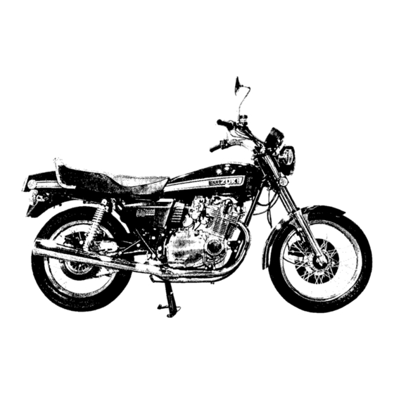
Suzuki GS1000 Service Manual (478 pages)
Brand:
Suzuki
| Category:
Motorcycle
| Size: 29.75 MB
Table of Contents
Product View
4
Group Index
6
General Information: Contents
8
Identification Table
9
Serial Number Location
9
Fuel, Oils and Breaking-In Procedure
9
Orientation
10
Braking-In Procedure
10
Location of Parts
10
Cylinder Identification
10
Service Specifications
11
Service Specifications: Contents
14
Engine Top End Specifications
15
Engine Lower End/Lubrication System/Clutch Specifications
17
Transmission/Fuel System Specifications
18
Ignition System/Charging System Specifications
19
Lamp Wattage, Brakes and Wheels Specifications
20
Tire Pressure, Suspension, Frame, Steering Specifications
21
Torque Table: Engine, Chassis
22
Tightening Torque Chart
23
Periodic Maintenance: Contents
24
Periodic Maintenance Schedule
25
Periodic Maintenance Procedures
26
Battery
26
Cylinder Head Nuts and Exhaust Pipe Bolts
26
Air Cleaner Element
27
Checking and Adjusting the Tappet Clearance
28
Tappet Clearance Adjustment
29
Shim Selection Chart
31
Spark Plug
32
Contact Breaker Points
32
Ignition Timing
32
Fuel Line
32
Timing Adjustment for Nos 1 and 4 Cylinders/For Nos 2 and 3 Cylinders
33
Engine Oil
34
Checking the Ignition Timing with the Timing Light
34
Engine Oil Filter
35
Carburetor Idle RPM
35
Throttle Cable Adjustment
35
Pulling Cable Play
35
Clutch
36
Drive Chain
36
Clutch Cable Adjustment
36
Returning Cable Play
36
Chain Cleaning and Oiling
38
Tires
38
Brake Hoses
38
Cleaning by Washing
38
Brakes
39
Steering
39
Front Forks
40
Chassis Bolts and Nuts
41
Special Materials
44
Use of Genuine Suzuki Parts
45
Special Tools
46
Troubleshooting: Contents
50
Engine and Chassis Troubleshooting
51
Electrical Troubleshooting
54
Engine: Contents
56
Engine Removal
58
Engine Remounting
60
Engine Overview
62
Compression Check
64
Top End Removal
64
Cylinder Head Cover Removal
64
Chain Tensioner Adjuster Removal
64
Camshaft, Cylinder Head Removal
65
Top End Installation
67
Valve Guide Hole Reaming
67
Valve Guide, Valve Stem Seal
67
Valve, Valve Springs
68
Installing Valve Cottter to Valve Stem
68
Cylinder Head Installation
68
Sprockets on Camshafts
69
Positioning Camshaft in Place
69
Camshaft Holder
71
Cam Chain Tensioner Adjuster
71
Tensioning Action Check
72
Top End - Inspection
73
Camshaft Journal Wear, Camshaft Wear
73
Camshaft Runout
74
Valve Face Wear
74
Valve Stem Deflection
75
Valve-To-Guide Clearance
75
Valve Seat Width Measurement
75
Valve Seat Servicing
76
Valve Spring
77
Cylinder Head Distortion
77
Cylinder Removal
78
Cam Chain Tensioner Adjuster Reassembling
78
Cylinder Installation
79
Distribution of Ring Gaps
79
Cylinder Wear Inspection
80
Piston and Rings Removal
80
Piston and Rings Installation
81
Piston Wear Determination Inspection
82
Piston Ring Clearance in the Groove Inspection
82
Lower End
83
Piston Ring Gap Inspection
83
Generator Stator Removal/Installation
83
Generator Rotor Removal/Installation
84
Contact Breaker Points Removal/Installation
85
Condenser Installation
85
Automatic Advancer for Contact Breaker Removal
85
Automatic Advancer for Contact Breaker Installation
86
Dismantling/Assembly of Automatic Advancer
86
Clutch Removal
87
Clutch Inspection
88
Free Length of Clutch Spring
88
Clutch Drive Plate Wear
88
Clutch Plate Distortion
88
Clutch Installation
89
External Mechanism for Gear Shift Removal/Installation
90
Engine Lubrication System Overview
91
Oil Pump Removal/Installation
92
Side, Tip Clearance
92
Outer Rotor Clearance in the Body
92
Oil Pump Pressure Test
93
Oil Filter Removal/Installation
94
Sump Filter Removal/Installation
94
Crankcase Removal
95
Crankshaft
96
Crankpin Wear and Big End Side Clearance
96
Transmission
97
Crankshaft Deflection
97
Mounting 2Nd Drive Gear on the Counter Shaft
97
Caution in Installation of Transmission Gears and Crankshaft on Crankcase
99
Gear Backlash
99
Fuel Cock/Fuel Tank Cleaning
101
Carburetors
101
Carburetors Description
102
Starter Unit
102
Fuel-Air Mixture too Lean/Too Rich
102
Pilot/Main Circuit
103
Float Unit
104
Needle Valve
104
Fuel System Disassembly
105
Fuel System Reassembly
106
Fuel System Adjustment
107
Fuel Level Measurement/Adjustment
108
Balancing Carburetors
108
Fuel System and Carburetor Troubleshooting
111
Emission Control and Regulations: Contents
112
Emission Control and Regulations
113
Emission Control Carburetor Components
114
General Emission Information
115
Carbon Monoxide
115
Engine/Carburetion Malfunction
115
Hydrocarbons
116
Mixture-Related/Ignition System Malfunctions
116
Chassis: Contents
118
Handlebar Removal/Mounting
119
Clutch Cable Removal
119
Clutch Cable Mounting
120
Throttle Cable Removal
120
Speedometer/Tachometer Cables Removal, Mounting
121
Throttle Cable Mounting
121
Headlamp Removal
122
Cautions in Mounting: Headlamp
122
Adjustment of Headlamp in Horizontal/Vertical Angle
122
Ignition Switch Removal, Mounting
123
Front Fork
124
Front Fork Removal/Mounting
125
Disassembly of Front Fork
126
Assembly of Front Fork
127
Measuring Method of Fork Oil Level
127
Handling the Front Fork
128
Adjusting the Air Fork
128
Inspection of Front Fork
129
Steering Stem Removal
129
Steering Stem Assembly
131
Steering Stem Tightening Method
131
Removal/Mounting of Steering Stem Race
133
Steering Stem Bearing Removal/Mounting
134
Front Wheel
134
Front Wheel Removal, Assembly
135
Front Wheel Inspection
136
Tire Warning
137
Removal of Tube and Tire
138
Front Wheel Mounting
139
Front Brake Master Cylinder Removal/Mounting
140
Air Bleeding the Brake Fluid Circuit
141
Master Cylinder Disassembly/Assembly
142
Inspection of Master Cylinder
143
Front Brake Caliper Removal/Mounting
144
Caliper
144
Caliper Disassembly/Assembly
145
Caliper Inspection
146
Brake Parts to be Periodically Replaced
146
Rear Brake Caliper Removal, Mounting
147
Air Bleeding of the Brake Fluid Circuit
148
Brake Pedal Adjustment
148
Pad Replacement
149
Disassembly/Assembly of Rear Brake Caliper
149
Pad Inspection
150
Rear Master Cylinder Removal
151
Rear Master Cylinder Mounting
152
Disassembly of Master Cylinder
152
Master Cylinder Assembly/Inspection
153
Rear Wheel
154
Rear Wheel Assembly
156
Rear Wheel Inspection, Chain Cleaning and Oiling
157
Rear Wheel Mounting
158
Checking the Sprockets for Wear
158
Adjustment of Wheel Alignment
158
Swing Arm Removal/Mounting
159
Disassembly of Swing Arm Bearing
160
Use of Special Tool
160
Swing Arm Mounting
161
Rear Shock Absorber
162
Spring/Damper Adjustment
162
Combination of Spring Setting and Damper Setting
163
Suspension Math between Front and Rear
163
Removal of Rear Shock Absorber
163
Swing Arm Assembly, Inspection
164
Electrical System: Contents
166
Ignition System: Data, Coils
167
Schematic Diagram of Ignition System
167
Contact Breakers
168
Charging System
170
Method of Testing Rectifier, Regulator and Alternator
170
Inspection of Charging System Components
171
Rectifier, Alternator
171
Starter System Inspection
172
Regulator
172
Starter Clutch and Generator Rotor
172
Inspection of Components
173
Carbon Brushes
173
Armature Coil, Commutator
173
Starter Motor Specifications
173
Battery Description, Specification
174
Relay for Starter Motor
174
Initial Changing Method
175
Initial Electrolyte Filling, Charging Current/Duration
175
Battery Servicing
176
Electrolyte Adjustment
176
Battery Removal, Installation, Inspection
176
Recharging Operation Based on S.G. Reading
176
Electrical System Troubleshooting
178
Utility Switches and Devices
178
Ignition Switch, Front Brake Lamp Switch
178
Rear Brake Lamp Switch, Lighting and Dimmer Switches
179
Turn Signal
179
Left Handle Switch, Kill Switch and Starter Switch
179
Horn
179
Oil Pressure Switch
180
Inspection of Headlamp
180
Lamp Wattage Data
180
Inspection of Tail Brake Lamps and Turn Signal Lamps
180
Rear Combination Lamps
181
Fuel Gauge
181
Inspection of Speedometer and Tachometer
181
Inspection of Fuel Meter and Gauge
183
Electrical System: Wiring Diagram
187
Electrical System: Cable Routing
188
GS1000E: Contents
193
GS1000E Overview
194
GS1000E Service Specifications
195
Front Brake
197
Master Cylinder Inspection
197
Caliper Inspection, Reassembly
197
Air Bleeding from Brake Fluid Circuit
197
Wheel
198
Wheel Disassembly, Inspection and Checking
199
Self-Cancelling Turn Signal: Circuit Diagram, Operation
200
Self-Cancelling Turn Signal: Troubleshooting
201
GS1000E Wiring Diagram
204
GS1000S: Contents
206
GS1000S: Overview
207
Service Data
210
Periodic Maintenance
217
Choke Cable, Choke Knob Adjustment
217
Carburetor Removal
217
Fuel System
218
Carburetor Disassembly
218
Chassis
219
Handlebar Removal
219
Choke Cable Removal, Installation
219
Clutch Cable Installation
219
Cowling Removal
220
Combination Meter Removal
221
Combination Meter Installation
222
Tube and Tire Removal
222
Tube and Tire Mounting
223
Electrical
224
Combination Meter Assembly/Disassembly
224
Power Source Terminal
226
Checking the Thermistor
226
GS1000S Wire and Cable Routing
227
GS1000S Wiring Diagram
229
GS1000L: Contents
231
Overviewing GS1000L
232
GS1000L Specifications
233
Service Data: GS1000L
235
Chassis Bolts and Nuts: Maintenance
242
Fuel Line, Cock
244
Choke Cable/Knob Adjustment
244
Carburetor Disassembly (GS1000L)
245
Chassis Front Fork
246
Front Fork Removal, Mounting
247
Front Wheel Removal, Mounting
248
Gear Shifting Switch and Gear Position Indicator
251
Fuel Gauge Wiring
252
GS1000L Wire and Cable Routing
257
Wiring Diagram for GS1000L
259
GS1000E/ST: Contents
264
GS1000ET Overview
265
GS1000ET Specifications
266
Torque Table
278
Fuel System of GS1000E/ST
291
Fuel Cock
292
Diaphragm and Piston Operation
295
Slow System
296
Main System
297
Starter, Float Systems
298
Float Height Adjustment
301
Fuel Level Measurement
305
Checking Fuel Level in each Float Chamber
305
Fuel Level Adjustment
305
Balancing the Carburetors
306
Fuel-Transistorized Ignition System
308
Signal Generator
309
Signal Generator Removal/Disassembly
310
Ignition Timing Inspection, Specifications
311
Signal Generator Resistance
312
Igniter
312
Charging Output Check
315
AC Generator No-Load Performance
315
Regulator/Rectifier
316
Front Master Cylinder
317
Master Cylinder Removal and Disassembly
318
Master Cylinder Inspection/Reassembly
320
Front Caliper
321
Brake Pad Replacement
322
Caliper Removal and Disassembly
323
Caliper and Disc Inspection
324
Caliper Reassembly
324
Wire and Cable Routing
326
Wiring Diagram of GS1000E/ST
328
GS1000ST Overview
329
GS1000E/ST Specifications
330
GS1000E/ST Service Data
332
GS1000E/ST Wire and Cable Routing
334
GS1000G/L Contents
345
GS1000GT Product View
346
GS1000GT Specifications
347
Engine Removal and Remounting
372
Secondary Bevel Gear Assembly
376
Secondary Drive Gear Assembly Removal and Disassembly
378
Bearing Preload Adjustment
380
Secondary Driven Gear Assembly: Removal and Disassembly
381
Secondary Driven Gear Assembly: Inspection and Reassembly
382
Secondary Gear Set Clearancing Operations
384
Backlash
384
Tooth Contact Checking
385
Final Assembly
386
Clutch Disassembly
388
Drive Plate Thickness, Drive Plate Claw Width
389
Clutch Spring Free Length
390
Crankcase Disassembly
392
Shift Fork - Groove Clearance
395
Drive Shaft and Gears
397
Notes on Installation of Transmission Gears and Crankshaft in Crankcase
398
Lubrication System
402
Shaft Drive
404
Final Drive Bevel Gear Assembly
406
Final Gear Case Breather Circuit
408
Air and Gear Oil Flow in Final Gear Case Breather Circuit
408
Final Drive Gear Preload Adjustment
413
Final Driven Gear Assembly
415
Final Gear Bearing Cover Shim Adjustment
416
Backlash Measurement
416
Tooth Contact Adjustment
418
Installation of Propeller Shaft and Final Drive Gear Assembly
420
Ignition Timing Specifications
424
Front Fork Inspection
431
Rear Wheel Overview
440
Rear Wheel Removal and Disassembly
441
Rear Swinging Arm
445
Disassembly of Swinging Arm Bearing
447
GS100GLT Overview
451
Advertisement
Suzuki GS1000 Service Manual (255 pages)
Brand:
Suzuki
| Category:
Motorcycle
| Size: 68.26 MB
Table of Contents
Specifications Service
11
Table of Contents
11
Service Specifications
12
Engine Top End
12
Engi?4E Lower End
14
Lubrication System
14
Clutch
14
Transmission
15
Fuel System
15
Charging System
16
SUSPENSION T FRAME
18
Torque Table
19
Engine
52
Engine Removal
54
Compression Check
59
Top End - Removal
59
Cylinder Head Cover
59
Chain Tenstoner Adjuster
59
Cylinder Head
61
Top End - Installation
63
Valve Guide Hole Reaming Is
63
Valve Guide
63
A L V E Stem Seal
63
Valve
64
VALVE Sprlngs
64
Valve Cotter to Valve Stem
64
Cylinder Head
64
Positioning Camshaft in Place
65
Camshaft Holder
67
Cam Chain Tensioner Adjuster
67
Tensioning Action Check
68
Tappet Clearance Adjustment
69
Top End - Inspection
69
Camshaft Journal Wear
69
Valve Stem Deflection
71
Valve-To-Guide Clearance
71
Valve Seat Width Measurement
71
Valve Seat Servicing
72
Valve Spring
73
Cylinder Head Flatness
73
Cam Chain Tensioner Adjuster
74
Cylinder
74
Removal
76
Inspection
76
Piston and Rings
76
Inspection
78
Lower End
79
Generator Stator
79
Generator Rotor
80
Contact Breaker Points
81
Condenser
81
Auto Matic Advancer for Contact Rreaker
81
Clutch
83
Removal
83
Inspection
84
Installation
85
External Mechanism for Gear Shift
86
Oil Pump
88
Oil Filter
90
Sump Filter
90
Crankcase
91
Crankshaft
92
Transmission
93
Chassis
114
Clutch Cable
115
Handlebar
115
Throttle Cable
116
Speedometer Cable
117
Tachometer Cable
117
Speedometer and Tachometer
118
Chassis
119
Headlamp
119
Front Fork
120
Steering Stem
125
Front Wheel
130
Steering Stem Bearing
130
Front Brake Master Cylinder
136
Front Brake Caliper
140
Caliper
143
Rear Master Cylinder
147
Rear Wheel
150
Swinging Arm
155
Rear Shock Absorber
158
Electrical System
161
Ignitionsystem
162
Spark Plug
163
Charging System
165
Inspection of Charging System Components
166
Starter System
167
Battery
169
Troubleshooting
173
Wiring Diagram
182
Table of Contents
186
Generalinformation
188
Service Specifications
188
Front Brake
190
Caliper
190
Wheel
191
Self-Cancelling Turn Signal
193
Circuit Diagram
193
Trouble Shooting
194
Wiring Diagram
197
Table of Contents
199
General Information
201
Specifications
201
Service Data
203
224
General Information
226
Specifications
226
Service Data
228
Periodic Maintenance
237
Chassis Bolts and Nuts
237
Engine Removal
239
Carburetor Removal
239
Fuel System
239
Fuel Line
239
Choke
239
Choke Cable Adjustment
239
Knob Adjustment
239
Fuel Systema N D Carburetors
239
Fuel Cock
239
Carburetor Disassembly
240
Chassis
241
Front Fork
241
Front Wheel
243
Tube and Tire
244
Rear Shock Absorber
245
Electrical
246
Position Indicator
246
Fuel Gauge
247
Wirea N Dcable Routing
252
Wire and Cable Rowing
253
Advertisement
Related Products
Suzuki GS1000G 1980
Suzuki GS1000S
Suzuki GS1100E
Suzuki GS1100EX 1981
Suzuki GS1100SZ 1982
Suzuki GS1100ED 1983
Suzuki GS1100ESD 1983
Suzuki GS1100SD 1983
Suzuki GS1100G 1982
Suzuki GS1100EZ 1982
Suzuki Categories
Motorcycle
Automobile
Motorcycle Accessories
Offroad Vehicle
Musical Instrument
More Suzuki Manuals
Login
Sign In
OR
Sign in with Facebook
Sign in with Google
Upload manual
Upload from disk
Upload from URL