Sign In
Upload
Manuals
Brands
Suzuki Manuals
Outboard Motor
DF9.9B
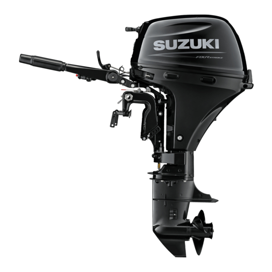
Suzuki DF9.9B Manuals
Manuals and User Guides for Suzuki DF9.9B. We have
2
Suzuki DF9.9B manuals available for free PDF download: Service Manual, Owner's Manual
Suzuki DF9.9B Service Manual (261 pages)
Brand:
Suzuki
| Category:
Outboard Motor
| Size: 19 MB
Table of Contents
Table of Contents
2
Lower Unit
2
Precautions
3
General Precautions
3
Precaution for Lower Unit
3
Precautions
5
Precaution for MID Unit
5
Wire / Hose Routing
9
Electrical Component Location
10
Housing and Bracket
11
Precautions
11
Precaution for Housing and Bracket
11
Service Instructions
11
Lower Side Cover Components
11
Lower Side Cover Removal and Installation
12
Tightening Torque
12
Tiller Handle and Handle Bracket Removal and Installation
12
Throttle Control Cable Installation and Adjustment
15
Steering Friction Adjuster Disassembly and Assembly
15
Tiller Handle Components
19
Tiller Handle Disassembly and Assembly
20
Engine Holder / Driveshaft Housing / Mounts Components
22
Engine Holder / Driveshaft Housing / Mounts Disassembly
24
Engine Holder / Driveshaft Housing / Mounts Assembly
25
Engine Holder / Driveshaft Housing / Mounts Related Component Inspection
28
Driveshaft Upper Oil Seal Replacement
29
Clamp / Swivel / Steering Brackets Components
30
Clamp / Swivel / Steering Brackets Disassembly
32
Clamp / Swivel / Steering Brackets Assembly
34
Clamp / Swivel / Steering Brackets Related Components Inspection
37
Important Notice
39
Precautions
40
Precautions for Powerhead
40
Right Hand Rotation Unit
41
Diagnostic Information and Procedures
41
Diagnose Lower Unit Malfunction
41
Service Instructions
42
Lower Unit Components
42
Propeller Removal and Installation
44
Propeller / Nut / Cotter Pin Inspection
44
Lower Unit Removal and Installation
45
Water Pump Removal and Installation
46
Water Pump and Related Items Inspection
48
Lower Unit Disassembly
48
Pinion Bearing Removal and Installation
51
Lower Unit Related Items Inspection
52
Propeller Shaft Oil Seal Replacement
55
Driveshaft Oil Seal Replacement
56
Lower Unit Assembly
56
Lower Unit Gears - Shimming and Adjustment
61
Initial Checking
62
Wire Routing
67
Wiring Diagram
67
Schematic and Routing Diagram
67
Wiring Harness Routing Diagram
69
Engine Control
77
Precautions
77
Precautions on Engine Control Diagnosis
77
General Description
78
Engine Control System Description
78
Engine Control Module (ECM)
81
Caution System Description
85
Self-Diagnostic System Description
87
Fail-Safe System Description
89
Oil Change Reminder System Description
90
Component Location
91
Engine Control System Components / Engine Electrical Device Location
91
Diagnostic Information and Procedures
91
Troubleshooting with Self-Diagnostic Code
91
Self-Diagnostic Code "3 - 4" MAP Sensor
91
Self-Diagnostic Code "1 - 4" Cylinder Temp
92
Troubleshooting
92
Self-Diagnostic Code "2 - 3" IAT Sensor
93
Self-Diagnostic Code "4 - 2" CKP Sensor
94
Self-Diagnostic Code "2 - 4" CMP Sensor
95
Self-Diagnostic Code "2 - 2" Air Intake System
96
Self-Diagnostic Code "3 - 2" MAP Sensor 2
97
Self-Diagnostic Code "4 - 3" Fuel Injector
98
Self-Diagnostic Code "2 - 1" TPS
99
Self-Diagnostic Code "1 - 1" Rectifier
99
Regulator (over Charging)
99
Self-Diagnostic Code "5 - 3" Oil Pressure Switch
100
Troubleshooting Without Self-Diagnostic Code
100
IAC System Troubleshooting
101
Service Instructions
102
How to Use the 26 Pin Test Cord
102
Inspection of the ECM and Its Circuit
103
ECM Removal and Installation
106
Caution Lamp Inspection
106
Precautions for Fuel / Water Hose Routing
108
Fuel Hose Routing
109
Water Hose Routing
112
Engine Electrical Devices
114
Precautions
114
Precaution for Engine Electrical Device
114
General Description
114
Sensor and Switch Description
114
Neutral Switch
116
Failure Symptoms
116
ECM Power Source
117
Component Location
118
Location of Sensor and Switch
118
Service Instructions
118
Resistance Check
118
ECM Power Source Coil Removal and Installation
119
ECM Power Source Coil Peak Voltage
119
Inspection
119
CKP Sensor Peak Voltage Inspection
119
CKP Sensor Removal and Installation
119
Cylinder Temp. Sensor Removal and Installation
120
Cylinder Temp. Sensor Inspection
121
IAT Sensor Removal and Installation
121
IAT Sensor Inspection
121
CMP Sensor Removal and Installation
122
CMP Sensor Inspection
122
MAP Sensor Removal and Installation
123
MAP Sensor Output Voltage Inspection
124
IAC Valve Removal and Installation
125
IAC Valve Inspection
125
TPS Inspection
125
Emergency and Engine Stop Switch Inspection
126
Cylinder Head Cover Removal and Installation
129
Power Unit Mechanical
129
General Description
129
Power Unit Construction Description
129
Diagnostic Information and Procedures
129
Cylinder Compression Check
129
Oil Pressure Check
129
Service Instructions
129
Valve Clearance Inspection
129
Recoil Starter Removal and Installation
129
Air Intake Silencer Case Removal and Installation
131
Intake Manifold and Throttle Body Components
132
Intake Manifold Removal and Installation
133
Throttle Body Removal and Installation
135
Throttle Body Inspection
135
Camshaft Pulley Removal and Installation
135
Power Unit Removal and Installation
136
Camshaft, Rocker Arm and Rocker Arm Shaft Removal and Installation
144
Camshaft, Rocker Arm and Rocker Arm Shaft Inspection
145
Cylinder Head Assembly Components
147
Cylinder Head Removal and Installation
148
Cylinder Head Disassembly and Assembly
149
Cylinder Head Components Inspection and Servicing
151
Pistons, Piston Rings, Connecting Rods, Cylinder and Crankshaft Components
158
Cylinder and Crankshaft Disassembly and Assembly
159
Cylinder, Piston and Piston Ring Inspection and Servicing
167
Cylinder Bore
168
Piston Pin and Conrod Inspection
170
Crank Pin and Conrod Inspection
171
Crankshaft Inspection
173
Crankshaft Main Bearing Inspection
174
Crankshaft Oil Seal Inspection
176
General Description
183
1F-1 Power Unit Cooling System
183
Water Cooling System Description
183
Displacement Type Water Pump Description
183
Schematic and Routing Diagram
184
Cooling Water Circulation Chart
184
Diagnostic Information and Procedures
185
Powerhead Cooling System Diagnosis
185
Thermostat Removal and Installation
185
Service Instructions
185
Thermostat and Related Items Inspection
186
Water Pump Removal and Installation
187
Water Pump Related Item Inspection
187
Water Tube Removal and Installation
187
Water Tube Related Item Inspection
187
Fuel System
188
Precautions
188
Precautions on Fuel System Service
188
General Description
189
Electronic Fuel Injection System Description
189
Fuel Delivery System Components Description
191
High Pressure Fuel Pump Control System Description
193
Air Intake Components Description
194
Idle Air Control System Description
196
Fuel Pressure Inspection
197
Fuel System Diagnosis
199
Fuel Injection System Troubleshooting
200
Service Instructions
201
Fuel Pressure Relief Procedure
201
Fuel Line Removal and Installation
201
Fuel Line Inspection
201
Fuel Leakage Check Procedure
201
Inspection of Fuel Hose Connections
202
Fuel Vapor Separator Removal and Installation
202
Inspection of Fuel Vapor Separator
203
High Pressure Fuel Pump Removal and Installation
203
High Pressure Fuel Pump Inspection
204
Fuel Injector Inspection with Injector in Place
204
Individual Fuel Injector Operating Sound Inspection
205
Fuel Injector Operating Signal Inspection
206
Fuel Injector Removal and Installation
207
Low Pressure Fuel Pump Removal and Installation
209
Low Pressure Fuel Pump Inspection
210
Fuel Tank Construction
211
Fuel Tank Disassembly and Reassembly
211
Fuel Tank Components Inspection
211
Ignition System
213
General Description
213
Ignition System Description
213
Ignition Control Description
214
Component Location
215
Ignition System Components Location
215
Ignition System Symptom Diagnosis
215
Ignition System Troubleshooting
215
Service Instructions
217
Spark Plug Removal and Installation
217
Spark Plug Inspection
217
Ignition Coil Removal and Installation
217
Ignition Coil Inspection
218
Spark Plug Cap Inspection
219
Ignition Coil Primary Peak Voltage Inspection
219
CKP Sensor Inspection
219
ECM Power Source Coil Inspection
219
Emergency and Engine Stop Switch Inspection
219
Starting System
220
General Description
220
Electric Starter System Description
220
Start-In-Gear Protection System Description
220
Component Location
221
Starting System Components Location
221
Diagnostic Information and Procedures
221
Starter System Symptom Diagnosis
221
Starter System Troubleshooting
222
Service Instructions
224
Starter Motor Removal and Installation
224
Starter Motor Test
225
Starter Motor Components
227
Starter Motor Disassembly and Assembly
227
Starter Motor Components Inspection and Servicing
229
Starter Motor Relay Inspection
233
Neutral Switch Inspection
234
Starter Button Inspection
235
Manual Starting System
236
Precautions
236
Precaution for Manual Starting System
236
General Description
236
Service Instructions
237
Recoil Starter Components
237
Recoil Starter Removal and Installation
238
Recoil Starter Disassembly and Assembly
239
Recoil Starter Components Cleaning and Inspection
242
NSI Cable Installation and Adjustment
243
Charging System
244
General Description
244
Charging System Description
244
Battery Requirement Description
245
Component Location
245
Charging System Components Location
245
Charging System Diagnosis
245
Service Instructions
246
Charging System Construction
246
Flywheel Removal and Installation
247
Battery Charge Coil / CKP Sensor / Stator Base Removal and Installation
248
ECM Power Source Coil / Battery Charge Coil / CKP Sensor / Stator Base Removal and Installation
253
Battery Charge Coil Inspection
258
Rectifier / Regulator Removal and Installation
258
Rectifier / Regulator Inspection
259
Battery Relay Inspection
260
Fuse Inspection
261
Advertisement
Suzuki DF9.9B Owner's Manual (71 pages)
Brand:
Suzuki
| Category:
Outboard Motor
| Size: 1 MB
Table of Contents
Table of Contents
4
Identification Number Location
5
Fuel and Oil
5
Location of Safety Labels
8
Location of Parts
10
Motor Mounting
15
Battery Installation
16
Use of Electrical Accessories
18
Battery Charge Cutout System (Df9.9Be/15Ae/20Ae)
18
Propeller Selection and Installation
19
Adjustment
20
Caution System
22
Diagnostic System
25
Oil Change Reminder System
25
Operation of Tilting Systems (Df9.9B/9.9Br/15A/15Ar/20A/20Ar)
26
Operation of Tilting Systems (Df9.9Bt/9.9Bth/15Ath/ 20At/20Ath)
29
Inspection before Boating
31
Break-In
32
Operation
33
Motor Removal and Transporting
46
Trailering
48
Inspection and Maintenance
49
Flushing the Water Passages
58
Submerged Motor
60
Storage Procedure
61
After Storage
62
Troubleshooting
62
Specifications
64
Information Regarding Ec - Directive
64
Flowchart of Oil Change Reminder System
65
Advertisement
Related Products
Suzuki DF9
Suzuki DF90A
Suzuki DF 90
Suzuki DF9,9
Suzuki DF90T
Suzuki DF175A
Suzuki DF350AMD
Suzuki DF300BMD
Suzuki DF140B
Suzuki DF115B
Suzuki Categories
Motorcycle
Automobile
Motorcycle Accessories
Outboard Motor
Offroad Vehicle
More Suzuki Manuals
Login
Sign In
OR
Sign in with Facebook
Sign in with Google
Upload manual
Upload from disk
Upload from URL