Sign In
Upload
Manuals
Brands
Supero Manuals
Motherboard
C7Z270-CG-L
Supero C7Z270-CG-L Manuals
Manuals and User Guides for Supero C7Z270-CG-L. We have
1
Supero C7Z270-CG-L manual available for free PDF download: User Manual
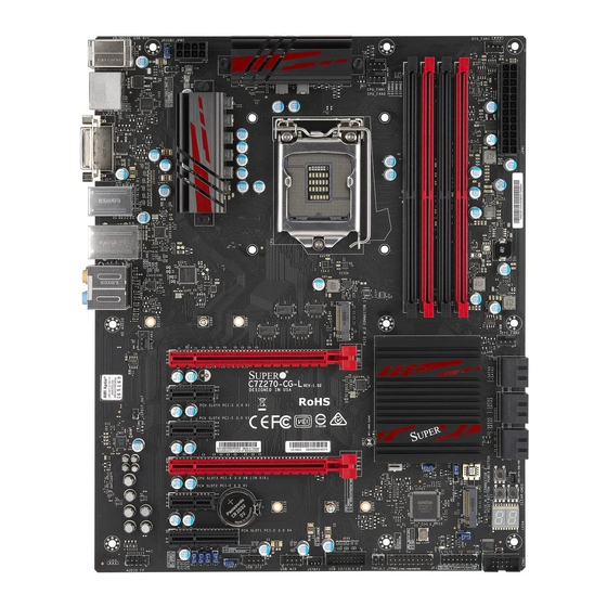
Supero C7Z270-CG-L User Manual (153 pages)
Intel Z270 Express chipset
Brand:
Supero
| Category:
Motherboard
| Size: 12 MB
Table of Contents
Manual Organization
3
Checklist
4
Conventions Used in the Manual
4
Standardized Warning Statements
5
Battery Handling
5
Product Disposal
6
Contacting Supermicro
8
Where to Find more Information
9
Table of Contents
10
Chapter 1 Introduction
19
Overview
19
About this Motherboard
19
Chipset Overview
19
Intel Z270 Express Chipset Features
19
Motherboard Features
20
Special Features
22
Recovery from AC Power Loss
22
PC Health Monitoring
22
Fan Status Monitor and Control
22
Environmental Temperature Control
22
System Resource Alert
23
ACPI Features
23
Slow Blinking LED for Suspend-State Indicator
23
Power Supply
24
Super I/O
24
Chapter 2 Installation
31
Installation Components and Tools Needed
31
Static-Sensitive Devices
32
Precautions
32
Unpacking
32
Processor and Heatsink Installation
33
Installing the LGA1151 Processor
33
Installing an Active CPU Heatsink with Fan
36
Removing the Heatsink
38
Installing DDR4 Memory
39
DIMM Installation
39
Removing Memory Modules
39
Memory Support
40
Memory Population Guidelines
41
Motherboard Installation
42
Tools Needed
42
Location of Mounting Holes
42
Installing the Motherboard
43
Connectors/Io Ports
44
Back I/O Panel
44
Universal Serial Bus (USB)
45
Ethernet Port
46
Back Panel High Definition Audio (HD Audio)
46
ATX PS/2 Keyboard/Mouse Ports
47
VESA® Displayport
47
HDMI Port
47
DVI Port
47
Front Control Panel
48
Front Control Panel Pin Definitions
49
Power LED
49
Hdd Led
49
Nic1 (Lan)
49
Overheat (Oh)/Fan Fail
49
Reset Button
50
Power Button
50
Connecting Cables
51
ATX Main PWR & CPU PWR Connectors (JPW1 & JPW2)
51
Fan Headers (Fan 1 ~ Fan 5)
52
Chassis Intrusion (JL1)
52
Speaker (JD1)
53
Thermistor Header (TH1)
53
Serial Port (COM1)
54
DOM PWR Connector (JSD1)
55
Spdif out (Jspdif_Out)
55
Standby Power Header (STBY1)
56
PCI-E M.2 Connector (PCI-E M.2)
56
Front Panel Audio Header (AUDIO FP)
57
Jumper Settings
58
Explanation of Jumpers
58
Manufacturing Mode (JPME2)
58
Clear CMOS & JBT1
59
PCI-E Slot SMB Enable (I2C1/I2C2)
59
Watch Dog Timer Enable/Disable
60
BIOS Recovery Jumper (JBR1)
60
Power Button (POWER BUTTON)
61
Reset Button
61
USB Wake up (JPUSB1)
61
Onboard Indicators
62
LAN Leds
62
Onboard Power LED (LED1)
62
Status Display (LED4)
63
Hard Drive Connections
64
SATA Connections (I-SATA0~I-SATA5)
64
Chapter 3 Troubleshooting
65
Troubleshooting Procedures
65
Before Power on
65
No Power
65
No Video
66
Memory Errors
66
When the System Is Losing the Setup Configuration
66
Technical Support Procedures
67
Frequently Asked Questions
68
Battery Removal and Installation
69
Battery Removal
69
Proper Battery Disposal
69
Returning Motherboard for Service
70
Battery Installation
70
Chapter 4 BIOS
71
Introduction
71
Starting BIOS GUI Setup Utility
71
How to Change the Configuration Data
72
How to Start the Setup Utility
72
System Information
73
System Date
73
System Time
73
Cpu
74
CPU Configuration
75
SW Guard Extension (SGX)
76
Select Owner EPOCH Input Type
76
PRMRR Size
76
Hardware Prefetcher
76
Adjacent Cache Line Prefetch
76
Intel (VMX) Virtualization Technology
76
Active Processor Cores
77
Hyper-Threading
77
Bist
77
Aes
77
Machine Check
77
Monitormwait
77
Intel Trusted Executed Technology
77
Alias Check Request
77
Reset AUX Content
77
FCLK Frequency for Early Power on
78
Power and Performance
78
CPU - Power Management Control
78
Race to Halt (RTH)
78
Intel(R) Speedstep(Tm)
79
HDC Control
79
C States
79
Enhanced C-States
79
C-State Auto Demotion
79
C-State Un-Demotion
79
Package C-State Demotion
79
Package C-State Un-Demotion
79
IO MWAIT Redirection
80
Package C State Limit
80
Package C State Workaround
80
GT-Power Management
80
CPU Overclocking
81
BCLK Clock Frequency (1/100 Mhz)
81
FCLK Frequency for Early Power on
81
Active Processor Cores
81
Load SMC CPU OC Setting
81
1-Core Ratio Limit Override
82
Boot Performance Mode
82
Intel(R) Speedstep(Tm)
82
Package Power Limit MSR Lock
82
Configurable TDP Boot Mode
82
Configurable TDP Lock
82
CTDP BIOS Control
83
Power Limit 1 Override
83
Power Limit 1
83
Power Limit 1 Time Window
83
Power Limit 2 Override
83
Power Limit 2
83
Platform PL1 Enable
83
Platform PL2 Enable
84
Power Limit 3 Override
84
Power Limit 4 Override
84
CPU Flex Ratio Override
84
CPU Flex Ratio Settings
84
Core Max OC Ratio
84
SA Voltage Override
84
Core Voltage Mode
84
Core Extra Turbo Voltage
84
Core Voltage Offset
85
Offset Prefix
85
Core PLL Voltage Offset
85
Ring Max OC Ratio
85
Ring Min OC Ratio
85
Uncore Voltage Offset
85
PCH Voltage
85
CPU_IO Voltage
85
PSYS Slope
85
PSYS Offset
86
PSYS Pmax Power
86
Acoustic Noise Settings
86
Acoustic Noise Mitigation
86
Core/Ia VR Settings
87
Memory
90
Memory Scrambler
90
Force Coldreset
90
Channel a DIMM Control
91
Channel B DIMM Control
91
Force Single Rank
91
Mrc Fast Boot
91
Memory Overclocking
91
Memory Profile
92
Memory Reference Clock
92
QCLK Odd Ratio
92
Memory Frequency
92
Memory Voltage
92
3Rd Timing
94
Advanced
99
Boot Feature
99
Quiet Boot
99
Bootup Num-Lock
99
Wait for "F1" if Error
99
Re-Try Boot
99
Watch Dog Function
100
Power Button Function
100
AC Loss Policy Depend on
100
Eup Support
100
NCT6792D Super IO Configuration
101
Superio Chip NCT6792D
101
Serial Port 1 Configuration
101
Serial Port
101
Device Settings
101
Change Settings
101
Serial Port Console Redirection
102
Com 1
102
Console Redirection
102
Console Redirection Settings
105
System Agent (SA) Configuration
106
PEG Port Feature Configuration
108
Program Pcie ASPM after Oprom
108
Program Static Phase1 Eq
108
Gen3 Root Port Preset Value for each Lane
108
Gen3 Endpoint Preset Value for each Lane
108
Lane 0 ~ Lane 15
108
Gen3 Endpoint Hint Value for each Lane
108
Gen3 Rxctle Control Lane
108
GMM Device (B0:D8:F0)
110
X2APIC Opt out
110
Graphics Configuration
111
Graphics Turbo IMON Current
111
Skip Scanning of External Gfx Card
111
Primary Display
111
Select PCIE Card
111
External Gfx Card Primary Display Configuration
111
Internal Graphics
112
GTT Size
112
Aperture Size
112
DVMT Pre-Allocated
112
DVMT Total Gfx Mem
112
Gfx Low Power Mode
112
VDD Enable
112
HDCP Support
113
Algorithm
113
PM Support
113
PAVP Enable
113
Cdynmax Clamping Enable
113
Graphics Clock Frequency
113
GT-Unsliced VR Settings
114
GT-Sliced VR Settings
117
PCH-IO Configuration
119
SATA and RST Configuration
120
SATA Controllers
120
SATA Mode Selection
120
SATA Controller Speed
120
SATA Frozen
121
Serial ATA Port
121
Hot Plug
121
Configured as Esata
121
Spin up Device
121
SATA Device Type
121
PCH FW Configuration
122
ME FW Image Re-Flash
122
Thunderbolt(Tm) Configuration
123
Thunderbolt (TM) Support
123
USB Configuration
124
Legacy USB Support
124
XHCI Hand-Off
124
Pcie/Pci/Pnp Configuration
126
Network Stack
127
Trusted Computing
128
Device Select
128
Security
129
Administrator Password
129
User Password
129
Secure Boot
130
Attempt Secure Boot
130
Secure Boot Mode
130
CSM Support
130
Key Management
131
Provision Factory Default Keys
131
Install Factory Default Keys
131
Enroll Efi Image
131
Save All Secure Boot Variables
131
Platform Key (PK)
131
Delete Key Exchange Key
132
Key Exchange Keys
132
Append Key Exchange Key
132
Delete Authorized Signature
132
Authorized Signatures
132
Append Authorized Signature
133
Delete Forbidden Signature
133
Forbidden Signatures
133
Append Forbidden Signature
133
Delete Authorized Timestamps
133
Authorized Timestamps
133
Append Authorized Timestamp
134
Delete Osrecovery Signatures
134
Osrecovery Signatures
134
Append Osrecovery Signature
134
Thermal & Fan
135
Fan Control
136
Fan Speed Control Mode
136
Save & Exit
137
Boot Mode Select
137
FIXED BOOT ORDER Priorities
137
Legacy Boot Option #1~#8
137
USB Key Drive BBS Priorities
137
NETWORK Drive BBS Priorities
137
Boot Override
138
Smi Usb Disk 1100
138
Launch EFI Shell from Filesystem Device
138
BIOS Update
140
Start Update
140
Appendix A BIOS Error Beep Codes
143
BIOS Error Beep Codes
143
Appendix B Software Installation Instructions
145
Installing Drivers
145
Configuring Superdoctor ® 5
146
Appendix C UEFI BIOS Recovery Instructions
147
An Overview to the UEFI BIOS
147
How to Recover the UEFI BIOS Image (-The Main BIOS Block
147
To Recover the Main BIOS Block Using a USB-Attached Device
148
Appendix D Dual Boot Block
151
Introduction
151
BIOS Boot Block
151
BIOS Boot Block Corruption Occurrence
151
D-2 Steps to Reboot the System by Switch JBR1
152
Advertisement
Advertisement
Related Products
Supero C7Z270-PG
Supero C7Z87-OCE
Supero C7Z97-OCE
Supero C7Z170-SQ
Supero C7Z170-M
Supero C7Z370-CG-L
Supero C7Z370-CG-IW
Supero Supero C7X99-OCE
Supero C7H170-M
Supero C7B250-CB-ML
Supero Categories
Motherboard
Server
Chassis
Computer Hardware
Desktop
More Supero Manuals
Login
Sign In
OR
Sign in with Facebook
Sign in with Google
Upload manual
Upload from disk
Upload from URL