Sign In
Upload
Manuals
Brands
Supero Manuals
Motherboard
Supero C7X99-OCE
Supero Supero C7X99-OCE Manuals
Manuals and User Guides for Supero Supero C7X99-OCE. We have
1
Supero Supero C7X99-OCE manual available for free PDF download: User Manual
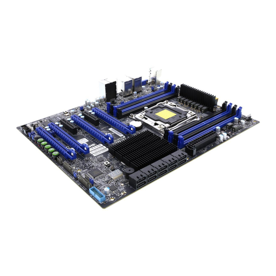
Supero Supero C7X99-OCE User Manual (147 pages)
Brand:
Supero
| Category:
Motherboard
| Size: 13 MB
Table of Contents
Manual Organization
3
Checklist
4
Conventions Used in the Manual
4
Standardized Warning Statements
5
Battery Handling
5
Product Disposal
6
Contacting Supermicro
8
Where to Find more Information
9
Table of Contents
10
Chapter 1
21
Introduction
21
Overview
21
About this Motherboard
21
Chipset Overview
21
Intel X99 Express Chipset Features
21
Motherboard Features
22
Special Features
24
Recovery from AC Power Loss
24
PC Health Monitoring
24
Fan Status Monitor with Firmware Control
24
Environmental Temperature Control
24
System Resource Alert
25
ACPI Features
25
Slow Blinking LED for Suspend-State Indicator
25
Power Supply
26
Super I/O
26
Chapter 2
31
Installation
31
Installation Components and Tools Needed
31
Static-Sensitive Devices
32
Precautions
32
Unpacking
32
Processor and Heatsink Installation
33
Installing the Processor
33
Installing a CPU Heatsink
37
Removing a Heatsink
38
Installing DDR4 Memory
39
DIMM Installation
39
Removing Memory Modules
39
Memory Population Guidelines
40
Memory Support
40
Motherboard Installation
42
Tools Needed
42
Location of Mounting Holes
42
Installing the Motherboard
43
Connectors/Io Ports
44
Back I/O Panel
44
Universal Serial Bus (USB)
45
Ethernet Ports
46
Back Panel High Definition Audio (HD Audio)
46
PS/2 Keyboard/Mouse Port
47
VGA Port (C7X99-OCE-F Only)
47
Front Control Panel
48
Front Control Panel Pin Definitions
49
Power LED
49
Hdd Led
49
Nic1/Nic2 (Lan1/Lan2)
49
Overheat (Oh)/Fan Fail
49
NMI Button
50
Power Fail
50
Reset Button
50
Power Button
50
Connecting Cables
51
ATX Main PWR & CPU PWR Connectors (JPW1 & JPW2)
51
Fan Headers (Fan 1 ~ Fan 5)
52
Chassis Intrusion (JL1)
52
Internal Buzzer (SP1)
53
Speaker (JD1)
53
DOM PWR Connector (JSD1)
54
Standby Power Header (STBY1)
54
System Management Bus (JIPMB1 )
54
TPM Header (JTPM1)
55
Power Supply I
55
C (Jpi2C1)
55
Front Panel Audio Header (AUDIO FP)
56
OC Front Panel (OC FRONT PANEL)
56
Jumper Settings
57
Explanation of Jumpers
57
LAN1/LAN2 Enable/Disable
57
Clear CMOS (JBT1, CLR_CMOS_SW)
58
PCI Slot SMB Enable (I C1/I C2)
58
Audio Enable (JPAC1)
59
Watch Dog Enable/Disable
59
USB Wake-Up (JPUSB1)
60
Over-Clock Management Buttons
61
Manufacturing Mode (JPME2)
62
VGA Enable/Disable (JPG1)
62
BMC Enable/Disable (JPB1)
62
BIOS Recovery Switch (JBR1)
63
Power Button (S4)
63
BIOS Restore (S11)
63
Onboard Indicators
64
LAN 1/LAN 2 Leds
64
BMC Heartbeat (LEDM1)
64
Power LED (LED1)
65
Status Display (LED4)
65
SATA Connections
66
SATA Connections (I-SATA0~I-SATA9)
66
The OC Front Control Panel (Optional)
67
Over-Clocking Buttons (OC1, OC2, OC3)
67
Clear CMOS and Reset
67
Boot BIOS Switch
67
BIOS Recovery
67
Front USB Port
67
Installing the OC Front Control Panel
68
Chapter 3
69
Troubleshooting
69
Troubleshooting Procedures
69
Before Power on
69
No Power
69
No Video
70
Memory Errors
70
When the System Is Losing the Setup Configuration
70
Technical Support Procedures
71
Frequently Asked Questions
72
Battery Removal and Installation
73
Battery Removal
73
Proper Battery Disposal
73
Returning Motherboard for Service
74
Battery Installation
74
Chapter 4 BIOS
75
Introduction
75
Starting BIOS GUI Setup Utility
75
How to Change the Configuration Data
76
How to Start the Setup Utility
76
Setup Home
77
Load Optimized Defaults
79
Save All Settings Only
79
Save Settings to OC3
79
Exit Without Save
79
Save and Reset
79
Save and Exit Setup
79
System Information
80
Motherboard
80
System Date
80
System Time
80
Cpu
81
Memory
82
Pch
83
Processor (CPU)
84
Information
84
Performance
85
Hyper-Threading [ALL]
85
Execute-Disable Bit Capability
85
PPIN Control
85
Hardware Prefetcher
85
Adjacent Cache Line Prefetch
86
DCU Streamer Prefetcher
86
DCU IP Prefetcher
86
Direct Cache Access (DCA Support)
86
X2Apic
86
Aes-Ni
86
Intel® Virtualization Technology
86
Power Management
87
Eist
87
Turbo Mode
87
P-STATE Coordination
87
Overclocking
89
CPU Overclocking
89
Load SMC CPU OC Setting
89
1-Core Ratio Limit
89
3-Core Ratio Limit
90
CPU Cache Ratio
90
BCLK Ratio
91
BCLK Clock Frequency (1/100 Mhz)
91
Internal PLL Overvoltage
91
CPU BCLK Filter PLL Frequency
91
LCPLL or SBPLL Select
91
CPU Non Turbo Ratio Override
91
CPU Power Setting
92
Enhanced Intel Speedstep Technology
92
Turbo Mode
92
CPU Turbo Setting
92
Package TDP Lock Enable
92
Long Duration Power Limit (Watt)
92
Long Duration Power Limit Time (Seconds)
92
Short Duration Power Limit Switch
92
Short Duration Power Limit (Watt)
92
Package Current Lock
93
Processor Current Limit (1/8 Amp)
93
Disable Overclocking Lock
93
Voltage Configuration
93
CPU Voltage Mode
93
CPU Adaptive Voltage Target (MV)
93
CPU Cache Voltage Mode
93
CPU Cache Adaptive Voltage Target (MV)
93
System Agent Voltage Offset (MV)
94
Overclocking SVID and FIVR Options
94
SVID Control Enable
94
SVID Override Voltage Target (MV)
94
FIVR Faults Enable
94
FIVR Efficiency Enable
94
CPU Overclocking
94
CPU Input Voltage
94
Memory Overclocking
95
Load Memory Profiles
95
Memory Timing Configuration (Expert Mode)
96
Chipset
99
System Agent
99
Intel VT for Directed I/O (VT-D)
100
Pch I/O
101
Azalia (HD Audio)
101
On Board Chip
102
Memory
103
Memory Information
103
Memory Configuration
104
Sata
105
SATA Controller
105
Configure SATA as
106
Ssata
108
Ssata Controller
108
Configure Ssata as
108
Pcie/Pci/Pnp
110
NB PCIE Setting
110
CPU SLOT1 PCI-E 3.0 X8 (in X16) - Gen X
110
CPU Port2 Bifurcate
110
CPU SLOT2 PCI-E 3.0 X8 (in X16) - Gen X
110
CPU SLOT4 PCI-E 3.0 X8 (in X16) - Gen X
110
CPU SLOT6 PCI-E 3.0 X16 - Gen X
110
Detect Non-Compliant Device
111
Above 4G Decoding
111
Cpu Slot1 Pci-E 3.0 X8 (in X16) Oprom
111
Cpu Slot2 Pci-E 3.0 X8 (in X16) Oprom
111
Pch Slot3 Pci-E 2.0 X1 (in X4) Oprom
111
Cpu Slot4 Pci-E 3.0 X8 (in X16) Oprom
111
Pch Slot5 Pci-E 2.0 X1 (in X4) Oprom
111
Cpu Slot6 Pci-E 3.0 X16 Oprom
111
Onboard LAN Option ROM Type
111
Onboard LAN1 Option Rom/Onboard LAN2 Option ROM
111
USB Settings
112
Legacy USB Support
112
XHCI Hand-Off
112
EHCI Hand-Off
112
XHCI Mode
113
Ehci1
113
Ehci2
113
PCH-FW (Firmware)
113
ME FW Image Re-Flash
114
Super IO Configuration
114
Current Config (IRQ)
114
Change (IRQ) Settings
114
Booting
115
Boot Device Settings
115
Boot Mode Select
115
Fixed Boot Order Priorities
115
Network Drive BBS Priorities
116
BIOS Features
116
Bootup Numlock State
117
Quiet Boot
117
Addon ROM Display Mode
117
Wait for "F1" for Error
117
Interrupt 19 Capture
117
Retry Boot
117
Watch Dog Function
117
Power Button Function
117
Restore on AC Power Loss
118
CSM Support
118
EUP Support
118
Fast Boot
118
Security Settings
119
Administrator Password
119
User Password
119
Secure Boot Menu
120
Secure Boot
120
Secure Boot Mode
120
Key Management
120
Default Key Provision
120
Enroll All Factory Default Keys
120
Save All Secure Boot Variables
120
Platform Key
120
Delete PK
120
Set New PK
121
Key Exchange Key
121
Delete KEK
121
Set New KEK
121
Append KEK
121
Authorized Signatures
121
Delete DBT
121
Set New DBT
121
Append DBT
122
Forbidded Signatures
122
Delete DBX
122
Set New DBX
122
Append DBX
122
Trusted Computing
123
Configuration
123
Current Status Information
123
Management
124
ACPI Settings
124
ACPI Sleep State
124
High Precision Event Timer
124
Console Redirection Settings
125
Com 1
125
Enable Console Redirection
125
Sol
127
Ipmi
131
System Event Log
131
SEL Components
131
Erasing Settings
132
Erase SEL
132
When SEL Is Full
132
BMC Network Configuration
132
Update IPMI LAN Configuration
133
Configuration Address Source
133
Appendix A
135
BIOS Error Beep Codes
135
Appendix B
137
Installing Drivers
137
Software Installation Instructions
137
Configuring Superdoctor ® III
138
An Overview to the UEFI BIOS
141
Appendix C
141
How to Recover the UEFI BIOS Image (-The Main BIOS Block
141
UEFI BIOS Recovery Instructions
141
To Recover the Main BIOS Block Using a USB-Attached Device
142
Appendix D
145
Dual Boot Block
145
Introduction
145
BIOS Boot Block
145
BIOS Boot Block Corruption Occurrence
145
Steps to Reboot the System by Switch JBR1
146
Advertisement
Advertisement
Related Products
Supero Supero C7X99-OCE-F
Supero C7X58
Supero C7Q67-H
Supero C7P67
Supero C7B75
Supero C7H61-L
Supero C7H61
Supero C7Z170-SQ
Supero C7B360-CB-M
Supero C7B360-CB-MW
Supero Categories
Motherboard
Server
Chassis
Computer Hardware
Desktop
More Supero Manuals
Login
Sign In
OR
Sign in with Facebook
Sign in with Google
Upload manual
Upload from disk
Upload from URL