Sign In
Upload
Manuals
Brands
Supermicro Manuals
Server
GEM002
Supermicro GEM002 Manuals
Manuals and User Guides for Supermicro GEM002. We have
1
Supermicro GEM002 manual available for free PDF download: User Manual
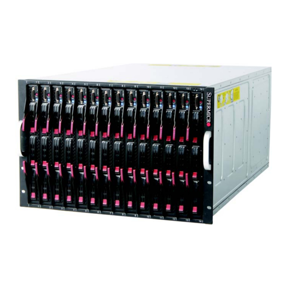
Supermicro GEM002 User Manual (66 pages)
compact self-contained server
Brand:
Supermicro
| Category:
Server
| Size: 7.25 MB
Table of Contents
About this Manual
3
Manual Organization
3
Table of Contents
5
Chapter 1 Introduction
13
Overview
13
Quickstart Setup
13
Officeblade and Datacenterblade Systems
14
Datacenterblade
15
Officeblade
15
Product Checklist of Typical Components
15
Blade Enclosure Features
16
Power
16
Middle Plane
17
Leds
17
Enclosure Cooling
17
Power Supply Features
18
Power Supply Modules
18
Power Cord
18
Power Supply Failure
18
Special Design Features
19
Operating System Support
19
Remote Management
19
Computing Density/Power
19
High-Efficiency Power Supplies
19
Contacting Supermicro
20
Returning Merchandise for Service
21
Chapter 2 System Safety
23
Electrical Safety Precautions
23
General Safety Precautions
24
Electrostatic Discharge Precautions
24
Operating Precautions
24
Chapter 3 Setup and Installation
25
Overview
25
Unpacking the System
25
Choosing a Setup Location
25
Rack Precautions
26
Server Precautions
26
Rack Mounting Considerations
26
Ambient Operating Temperature
26
Reduced Airflow
26
Mechanical Loading
26
Circuit Overloading
27
Reliable Ground
27
Installing the System into a Rack
27
Rack Mounting Hardware
27
Installation
28
Figure 3-1. Positioning the Enclosure Template
28
Figure 3-2. Securing the Rails to the Rack
28
Figure 3-3. Attaching the Optional Handles
29
Figure 3-4. Enclosure Installed into Rack
30
Chapter 4 System Modules
31
Figure 4-1. Typical Blade System Module Configuration: Rear View
31
Table 4-1. Typical Blade System Module Configuration: Rear View
31
Chassis Management Module
32
Figure 4-2. Chassis Management Module
32
Table 4-2. CMM Module Interface
32
Module Redundancy
33
Master/Slave Modules
33
Table 4-3. CMM Module Features
33
Configuring the CMM
34
Module Installation
34
Figure 4-3. Choose Internal Protocol
35
Figure 4-4. Manually Configure the IP Address
36
CMM Functions
37
Figure 4-5. Changing Settings
37
Local KVM
38
Monitoring Functions
38
Remote KVM over IP
38
Remote Storage (Virtual Media)
38
Serial over LAN (SOL)
38
Power Consumption Management
39
CMM Switches and Buttons
39
USB Switch
39
Figure 4-6. USB Switch on Rear of CMM
39
Reset Button
40
Firmware
40
Web-Based Management Utility
40
Table 4-4. CMM Reset Settings
40
Address Defaults
41
Network Connection/Login
41
Supported Browsers
41
Table 4-5. Address Defaults
41
Figure 4-7. Home Page
42
Home Page
42
Table 4-6. Home Page Controls
42
Double-Wide Modules
43
Figure 4-8. Horizontal Spacers for Single Bays
44
Figure 4-9. Modifying for a Double-Wide Module Bay (Steps 1 & 2)
45
Figure 4-10. Modifying for a Double-Wide Module Bay (Steps 3 & 4)
46
Chapter 5 Power Supply Modules
47
Power Supply Modules
47
Figure 5-1. PWS-1K41-BR Power Supply
47
Table 5-1. PWS-1K41-BR Power Supply Features
47
Figure 5-2. PWS-2K01-BR Power Supply
48
Table 5-2. PWS-2K01-BR Power Supply Features
48
Installing a Power Supply
49
Power Supply Failure
49
Removing a Power Supply
50
Power Supply Fans
50
Figure 5-3. Power Supply Module
50
Power Components
51
Power Cord
51
Figure 5-4. Power Components
51
Table 5-3. Power Components
51
Power Cable Tie and Clamp
52
Figure 5-5. Power Cable Tie and Clamp Parts
52
Figure 5-6. Power Cable Tie and Clamp Assembly
53
Appendix A System Specifications
55
Enclosure Specifications
55
Table A-1. Enclosure Specification Features
55
Environmental Specifications
56
Address Defaults
56
Table A-2. Environmental Specification Features
56
Table A-3. Address Default Features
56
Power Supply Power Calculations
57
Table A-4. Power Supply: Power Calculations (PWS-2K01-BR
57
Table A-5. Power Supply: Power Calculations (PWS-1K41-BR
57
Appendix Bled Descriptions
59
Blade Enclosure LED Descriptions
59
Table B-1. Blade Enclosure: LED Descriptions
59
Blade Module LED Descriptions
60
Table B-2. Blade Module LED Indicators
60
1/10 Gigabit Ethernet Module LED Descriptions
61
Table B-3. 1/10 Gbe Switch and 10-Gbe Pass-Through Module LED Indicators
61
Table B-4. Stacking LED Activity (SBM-GEM-X2C
61
Gigabit Ethernet Module LED Descriptions
62
Table B-5. Gigabit Ethernet Switch LED Indicators
62
Infiniband Switch LED Descriptions
63
Table B-6. Infiniband Switch Leds
63
Advertisement
Advertisement
Related Products
Supermicro GS7
Supermicro 1012A-MTF
Supermicro 1019S-MP
Supermicro 1020A-8
Supermicro 1020A-T
Supermicro 1027R-73DAF
Supermicro 1028-WTNR(T)
Supermicro 1029P-WTRT
Supermicro 1029U-TRTP
Supermicro Categories
Server
Motherboard
Computer Hardware
Chassis
Switch
More Supermicro Manuals
Login
Sign In
OR
Sign in with Facebook
Sign in with Google
Upload manual
Upload from disk
Upload from URL