Sign In
Upload
Manuals
Brands
Summit Manuals
Control Panel
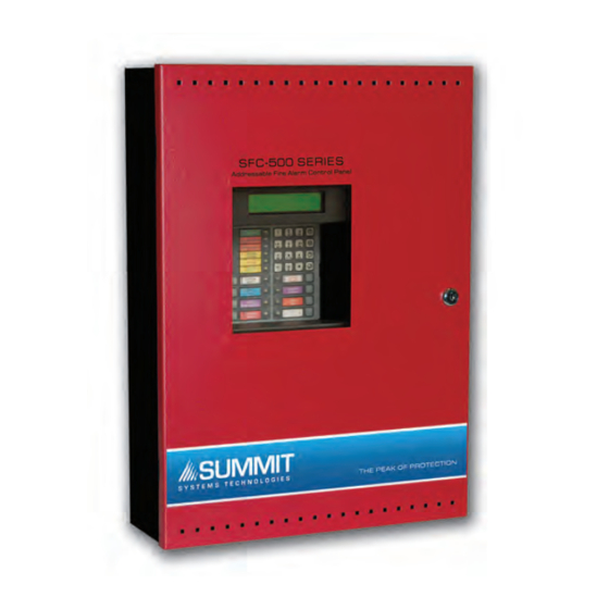
SFC-500 SERIES
Summit SFC-500 SERIES Manuals
Manuals and User Guides for Summit SFC-500 SERIES. We have
1
Summit SFC-500 SERIES manual available for free PDF download: Installation Instructions Manual
Summit SFC-500 SERIES Installation Instructions Manual (60 pages)
FIRE ALARM PANEL
Brand:
Summit
| Category:
Control Panel
| Size: 2 MB
Table of Contents
Installation Instructions
1
Table of Contents
3
Industry Canada and FCC Notice
7
Notice for All SFC-500 Series Built-In Udacts Sold in the U.S.A
7
Introduction
8
Features
8
Conventions
9
Circuits
9
Zone/Group
9
Display Points
9
Wiring Styles
9
System Components
10
Panel Models
10
Output Class a Converter: Four Circuits
11
Polarity Reversal/City Tie
11
Remote Annunciator
12
Smart Relay Module
12
SRAM-216 Remote Annunciator
12
Panel Components and System Accessories
13
Analog/Addressable Devices
14
Mechanical Installation
15
Installing the Enclosure
15
Figure 1: Wallbox Dimensions / Mounting the SFC-500 - Surface
15
Figure 2: Mounting the SFC-500 - Flush
16
Figure 3: Flush Trim Detail
16
Figure 4: Wallbox Dimensions / Mounting the SFC-551/SFC-553 - Surface /Flush
17
Installing Adder Modules
18
Figure 5: Installation of Adder Modules
18
Cable and Jumper Connections for Main Board and Adder Modules
19
Figure 6: Main Fire Alarm Board Cable Connectors and Jumper Locations
19
Figure 7: Main Board (3 Loop Model) Cable Connectors and Jumper Locations
20
SOCA-204 Output Class a Converter Adder Module
21
Figure 8: SOCA-204 Output Class a Converter Adder Modules
21
Polarity Reversal and City Tie Module (Model SPR-200)
22
SRAX-532 Display Adder Module
22
Figure 9: Polarity Reversal and City Tie Module
22
Circuits and Devices
23
Addressable/Analog Devices
23
Analog Devices
24
Contact Inputs
24
Contact Outputs
24
Field Wiring
25
Main Fire Alarm Board Field Wiring
25
Loop Isolators
25
Figure 10: Addressable Loop Wiring - Class B or Style 4
25
Loop Operation
26
Figure 11: Addressable Loop Wiring -Class a or Style 6
26
Indicating (Powered Output) Circuits
27
Indicating Circuit Wiring
27
Figure 12: Indicating Circuit - Class B or Style y Wiring
28
Figure 13: Indicating Circuit -Class a or Style Z Wiring
28
Dialer Wiring
29
Figure 14 Dialer Wiring
29
Polarity Reversal and City Tie Module (SPR-200) Wiring
30
Figure 15: Polarity Reversal and City Tie Module Terminal Connection
30
Auxiliary Power Supplies
31
Figure 16: Supervision of Auxiliary Supplies
31
Power Supply Connections
32
Figure 17: Main Power Supply Connections
32
System Checkout
33
Before Turning the Power "ON
33
Power-Up Procedure
33
Troubleshooting
33
Indicators, Controls and Operations
34
Figure 18: LCD Display, LED Indicators and Control Buttons
34
Common Indicators
35
Common Controls
36
Single Stage Operation
37
Two-Stage Operation
38
Positive Alarm Sequence
39
Enabling or Disabling the Positive Alarm Sequence
39
If You Do Not Wish the Change the Status, Press the "Cancel" Key
40
Input Types
40
Output Types
42
Evacuation Codes
43
Figure 19: Evacuation and Alert Codes
43
Remote Annunciators Operation
46
Dialer Operation
47
Appendix A: Compatible Receivers
47
Appendix B: Reporting
48
Ademco Contact-ID
48
Security Industries Association SIA-DCS
49
Appendix C: Specifications
50
Appendix D: Power Supply and Battery Calculations
51
Warranty & Warning Information
53
Warning Please Read Carefully
53
Limited Warranty
55
Warranty Procedure
55
Disclaimer of Warranties
55
Out of Warranty Repairs
56
Advertisement
Advertisement
Related Products
Summit SFC-102 Series
Summit SM900BL
Summit SCFF495
Summit SMB-200
Summit SM1100WH
Summit SCR610BL
Summit SCR314L
Summit SWKD571
Summit SCR1536BG
Summit SBC696OSNK
Summit Categories
Refrigerator
Freezer
Cooktop
Kitchen Appliances
Wine Cooler
More Summit Manuals
Login
Sign In
OR
Sign in with Facebook
Sign in with Google
Upload manual
Upload from disk
Upload from URL