Sign In
Upload
Manuals
Brands
Stober Manuals
Servo Drives
EZ
Stober EZ Manuals
Manuals and User Guides for Stober EZ. We have
3
Stober EZ manuals available for free PDF download: Manual, Operating Manual, Connection Manual
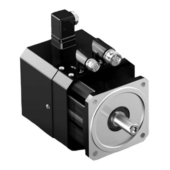
Stober EZ Manual (460 pages)
Synchronous servo geared motors with redundant brake
Brand:
Stober
| Category:
Industrial Equipment
| Size: 16 MB
Table of Contents
4 Phq Planetary Geared Motors
63
Table of Contents
63
Overview
64
Selection Tables
65
Dimensional Drawings
67
F Shaft Design (Flange Shaft)
68
Type Designation
70
Nameplate
70
Product Description
71
Input Options
71
Servostop Motor Adapter with Brake (MB)
71
Installation Conditions
73
Mounting Positions
74
Lubricants
74
Other Product Features
74
Direction of Rotation
74
Project Configuration
75
Drive Selection
76
Permitted Shaft Loads for the Output Shaft
81
Recommendation for Radial Shaft Seal Rings
82
Reverse Operation
82
Additional Documentation
83
5 C Helical Geared Motors
85
Overview
86
Selection Tables
87
Dimensional Drawings
111
Solid Shaft Design with Feather Key, N Housing Design (Foot)
112
Solid Shaft Design with Feather Key, G Housing Design (Pitch Circle Diameter)
114
Solid Shaft Design with Feather Key, F Housing Design (Round Flange)
116
Solid Shaft Design with Feather Key, Q Housing Design (Square Flange)
118
Oil Expansion Tank
120
Nameplate
121
Type Designation
121
Input Options
122
Product Description
122
Servostop Motor Adapter with Brake (MB)
122
Housing Design
125
Installation Conditions
125
Shaft Design
125
Lubricants
126
Mounting Positions
126
Maintenance
127
Other Product Features
127
Position of the Plug Connectors/Terminal Box
127
Direction of Rotation
128
Project Configuration
128
Drive Selection
129
Permitted Shaft Loads for the Output Shaft
134
Additional Documentation
135
Oil Expansion Tank
135
Radial Shaft Seal Rings
135
6 F Offset Helical Geared Motors
137
Overview
138
Selection Tables
139
Dimensional Drawings
147
A Shaft Design (Hollow Shaft), G Housing Design (Pitch Circle Diameter)
148
A Shaft Design (Hollow Shaft), GN Housing Design (Pitch Circle Diameter + Side Fastening)
150
A Shaft Design (Hollow Shaft), F Housing Design (Round Flange)
152
A Shaft Design (Hollow Shaft), Q Housing Design (Square Flange)
154
Shaft Design (Solid Shaft), F Housing Design (Round Flange)
156
Shaft Design (Solid Shaft), Q Housing Design (Square Flange)
158
S Shaft Design (Hollow Shaft with Shrink Ring), G Housing Design (Pitch Circle Diameter)
160
S Shaft Design (Hollow Shaft with Shrink Ring), GN Housing Design (Pitch Circle Diameter + Side Fastening)
162
S Shaft Design (Hollow Shaft with Shrink Ring), F Housing Design (Round Flange)
164
S Shaft Design (Hollow Shaft with Shrink Ring), Q Housing Design (Square Flange)
166
Nameplate
168
Type Designation
168
Input Options
169
Product Description
169
Servostop Motor Adapter with Brake (MB)
169
Combinatorial Shaft/Housing Design
172
Housing Design
172
Installation Conditions
172
Lubricants
173
Mounting Positions
173
6.5.10 Direction of Rotation
174
Other Product Features
174
Position of the Plug Connectors/Terminal Box
174
Project Configuration
175
Drive Selection
176
Permitted Shaft Loads for the Output Shaft
181
Additional Documentation
183
Radial Shaft Seal Rings
183
7 Pk Right-Angle Planetary Geared Motors
185
Overview
186
Selection Tables
187
Dimensional Drawings
201
P Shaft Design (Solid Shaft with Feather Key)
202
G Shaft Design (Solid Shaft Without Feather Key)
204
Nameplate
206
Type Designation
206
Input Options
207
Product Description
207
Servostop Motor Adapter with Brake (MB)
207
Installation Conditions
209
Lubricants
210
Mounting Positions
210
Direction of Rotation
211
Other Product Features
211
Position of the Plug Connectors/Terminal Box
211
Project Configuration
212
Drive Selection
213
Permitted Shaft Loads for the Output Shaft
218
Recommendation for Radial Shaft Seal Rings
220
Reverse Operation
220
Additional Documentation
221
8 Phk Right-Angle Planetary Geared Motors
223
Overview
224
Selection Tables
225
Dimensional Drawings
239
F Shaft Design (Flange Shaft)
240
Type Designation
242
Type Designation PH5K_ − PH8K
242
Nameplate
243
Type Designation PH9K_ − PH10K
243
Input Options
244
Product Description
244
Servostop Motor Adapter with Brake (MB)
244
Installation Conditions
246
Lubricants
247
Mounting Positions
247
Direction of Rotation
248
Other Product Features
248
Position of the Plug Connectors/Terminal Box
248
Project Configuration
249
Drive Selection
250
Permitted Shaft Loads for the Output Shaft
255
Recommendation for Radial Shaft Seal Rings
256
Additional Documentation
257
Reverse Operation
257
9 Phqk Right-Angle Planetary Geared Motors
259
Overview
260
Selection Tables
261
Dimensional Drawings
277
PHQ5 − PHQ10 F Shaft Design (Flange Shaft)
278
PHQ11 − PHQ12 F Shaft Design (Flange Shaft)
280
Type Designation
282
Type Designation PHQ5K_ − PHQ8K
282
Nameplate
283
Type Designation PHQ9K_ − PHQ12K
283
Input Options
284
Product Description
284
Servostop Motor Adapter with Brake (MB)
284
Installation Conditions
286
Lubricants
287
Mounting Positions
287
Direction of Rotation
288
Other Product Features
288
Position of the Plug Connectors/Terminal Box
288
Project Configuration
289
Drive Selection
290
Permitted Shaft Loads for the Output Shaft
295
Recommendation for Radial Shaft Seal Rings
296
Additional Documentation
297
Reverse Operation
297
10 K Helical Bevel Geared Motors
299
Overview
300
Selection Tables
301
Dimensional Drawings
323
A Shaft Design (Hollow Shaft), G Housing Design (Pitch Circle Diameter)
324
A Shaft Design (Hollow Shaft), NG Housing Design (Foot + Pitch Circle Diameter)
326
A Shaft Design (Hollow Shaft), GD Housing Design (Pitch Circle Diameter + Torque Arm Bracket)
328
A Shaft Design (Hollow Shaft), F Housing Design (Round Flange)
330
A Shaft Design (Hollow Shaft), NF Housing Design (Foot + Round Flange)
332
S Shaft Design (Hollow Shaft with Shrink Ring), G Housing Design (Pitch Circle Diameter)
334
S Shaft Design (Hollow Shaft with Shrink Ring), NG Housing Design (Foot + Pitch Circle Diameter)
336
S Shaft Design (Hollow Shaft with Shrink Ring), GD Housing Design (Pitch Circle Diameter + Torque Arm Bracket)
338
S Shaft Design (Hollow Shaft with Shrink Ring), F Housing Design (Round Flange)
340
S Shaft Design (Hollow Shaft with Shrink Ring), NF Housing Design (Foot + Round Flange)
342
Shaft Design (Solid Shaft), G Housing Design (Pitch Circle Diameter)
344
Shaft Design (Solid Shaft), NG Housing Design (Foot + Pitch Circle Diameter)
346
Shaft Design (Solid Shaft), F Housing Design (Round Flange)
348
Shaft Design (Solid Shaft), NF Housing Design (Foot + Round Flange)
350
10.3.15 Oil Expansion Tank
352
Type Designation
353
Input Options
354
Nameplate
354
Product Description
354
Servostop Motor Adapter with Brake (MB)
355
10.5.3 Housing Design
358
10.5.4 Combinatorial Shaft/Housing Design
359
10.5.6 Mounting Positions
359
Installation Conditions
359
10.5.8 Position of the Plug Connectors/Terminal Box
361
Lubricants
361
10.5.10 Maintenance
362
10.5.9 Other Product Features
362
10.5.11 Direction of Rotation
363
Project Configuration
364
Drive Selection
365
10.6.2 Permitted Shaft Loads for the Output Shaft
370
10.6.3 Radial Shaft Seal Rings
372
10.6.4 Oil Expansion Tank
372
Additional Documentation
373
11 Ez Synchronous Servo Motors
375
Overview
376
Selection Tables
377
EZ Motors with Convection Cooling
378
EZ Motors with Forced Ventilation
379
Torque/Speed Curves
380
Dimensional Drawings
390
EZ2 - EZ3 Motors (One Cable Solution)
390
EZ2 - EZ3 Motors
391
EZ4 - EZ7 Motors with Convection Cooling (One Cable Solution)
392
EZ4 - EZ8 Motors with Convection Cooling
393
EZ4 - EZ7 Motors with Forced Ventilation (One Cable Solution)
394
EZ4 - EZ8 Motors with Forced Ventilation
395
Nameplate
396
Type Designation
396
Electrical Features
397
General Features
397
Product Description
397
Ambient Conditions
398
Encoders
398
Temperature Sensor
400
Cooling
402
Holding Brake
403
Connection Method
405
Drive Selection
411
Project Configuration
411
Permitted Shaft Loads
412
Derating
414
Additional Documentation
415
Directives and Standards
415
Further Information
415
Identifiers and Test Symbols
415
13 Connecting to Drive Controllers of Third-Party Manufacturers
419
General Notes
420
Nominal Data
420
Plug Connectors
421
Connection Cables
422
Connection to B&R Drive Controllers
423
Encoders
423
Possible Combinations with Drive Controllers
425
Connection Assignment of the Power Plug Connector
426
13.2.4 Connection Assignment of the Encoder Plug Connector
427
Terminal Assignment for Plug Connectors (One Cable Solution)
428
Connection to Siemens Drive Controllers
429
EIB 3392S Interface
429
Encoders
430
Possible Combinations with Drive Controllers
431
13.3.4 Connection Assignment of the Power Plug Connector
432
Connection Assignment of the Encoder Plug Connector
432
13.4.2 Possible Combinations with Drive Controllers
434
Connection to Kollmorgen Drive Controllers
434
Encoders
434
13.4.3 Connection Assignment of the Power Plug Connector
435
13.4.4 Connection Assignment of the Encoder Plug Connector
436
Connection to Bosch Rexroth Drive Controllers
437
Encoders
437
Connection Assignment of the Power Plug Connector
438
Possible Combinations with Drive Controllers
438
13.5.4 Connection Assignment of the Encoder Plug Connector
439
Connection to Beckhoff Drive Controllers
440
Encoders
440
Possible Combinations with Drive Controllers
440
13.6.4 Connection Assignment of the Encoder Plug Connector
441
Connection Assignment of the Power Plug Connector
441
Connection to Allen-Bradley Drive Controllers
442
Encoders
442
Possible Combinations with Drive Controllers
442
Terminal Assignment of the Power Plug Connector
442
Terminal Assignment of the Encoder Plug Connector
443
Terminal Assignment for Plug Connectors (One Cable Solution)
444
Advertisement
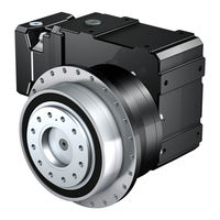
Stober EZ Operating Manual (7 pages)
synchronous servo motors, synchronous servo motors for screw drive
Brand:
Stober
| Category:
Servo Drives
| Size: 0 MB
Table of Contents
1 Operation in Accordance with Its Intended Use
1
2 Technical Data
1
2.1 Thermal Winding Protection
2
2.1.1 Thermal Winding Protection PTC
2
2.1.2 Thermal Winding Protection KTY (Optional)
2
2.2 Encoder Systems
2
Motor Cooling
3
2.3 Holding Brake (Optional)
3
2.3.1 Brakes on Gravity-Loaded Vertical Axes
3
2.3.2 Testing Holding Brake
3
2.4.1 Forced-Air Cooling (Optional)
3
2.4.2 Water Cooling (Optional)
3
Safety Information
4
Safety During Installation and Maintenance
4
Personnel Requirements
4
3.2 in the Event of Disruptions
4
3.4 Safe Function and EMC of the Drive System
4
3.5 EZF, EZH, EZHD, EZHP Synchronous Servo Motors
5
3.6 Servo Spindle Motors EZS/EZM
5
4 Transport, Storage and Preservation
5
Maintenance
6
Troubleshooting
6
5 Mounting
6
6 Commissioning
6
9 Spare Parts
6
10 Disposal
6
Stober EZ Connection Manual (2 pages)
Synchronous servo motor EZ to B&R ACOPOS (EZ_HQ)_Customer KRONES
Brand:
Stober
| Category:
Engine
| Size: 0 MB
Advertisement
Advertisement
Related Products
Stober Categories
Engine
Controller
Inverter
DC Drives
Industrial Equipment
More Stober Manuals
Login
Sign In
OR
Sign in with Facebook
Sign in with Google
Upload manual
Upload from disk
Upload from URL