Sign In
Upload
Manuals
Brands
STEYR MOTORS Manuals
Engine
SE236E40
STEYR MOTORS SE236E40 Manuals
Manuals and User Guides for STEYR MOTORS SE236E40. We have
4
STEYR MOTORS SE236E40 manuals available for free PDF download: Service Manual, Installation Manual, Operation, Maintenance And Warranty Manual
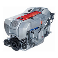
STEYR MOTORS SE236E40 Service Manual (274 pages)
Brand:
STEYR MOTORS
| Category:
Engine
| Size: 16 MB
Table of Contents
Table of Contents
9
Ageneral Remarks
11
A 1 Model and Serial Number
11
A 2 Documentation
12
A 3 Technical Data and Overview
13
A 3.2 Overview Engine M16 TCA
22
B Specification
23
B 1 Fuel Requirements
23
B 2 Motor Oil
25
C Maintenance and Service
26
C 1 Trouble Check Chart
26
C1 Trouble Check Chart Continued
27
Service- and Maintenance Schedule
30
D General Information
33
D 1 Electronic Engine Management System
33
Diagnostic System
37
Operation after Break - in
42
Extended Storage Preservation Procedure
42
E Quality Guidelines for Repair
44
E 1 Spare Part Specification
44
E 2 Workshop Profile
44
E 3 Nomenclature
45
E 4 si - System
47
E 5 Abbreviations
48
F Operating Material and Information on Disposal
49
F 1 List of Operating Material
49
F 2 Disposal of Automotive Waste Products
50
G Notes on Safety
51
G 1 General Notes on Safety
52
G 2 Guidelines for Damage Prevention
52
G 3 Legal Rules
52
G 4 Safety in the Use of Operating Material
53
G 5 Measures in Case of Accidents
53
H Tightening Torques
54
H 1 Listing of Tightening Torques
54
H 2 General Tightening Torques
60
H 3 Testing of Torque Wrenches
61
H 4 Non-Destructive Material Testing
61
H 5 Use of Adhesive and Sealing Materials
61
H 6 Solvent-Free Sealing Materials
61
I Wear Limits
64
I 1 Adjustment Information for Service and Maintenance
65
Engine Timing (Measured with Dial Indicator No. 2300899/0)
65
Tension Timing Belt (Measured with Tool VR00515/0)
65
Start of Fuel Delivery on the Unit Injectors (Measured with Dial Indicator No. 2300899/0)
65
Valve Clearance (Measured with Tool No. 2300712/3))
65
Engine Timing, Engine Mount
70
Lock Crank Shaft (Piston No. 1 at TDC)
70
Camshaft Housing Cover and Seal
73
Remove Timing Belt
82
Replace Engine Bracket
93
Cylinder Block
94
Replace Valves
94
Adjust Valve Clearance
96
Replace Valve Guide
97
Replace Pressure Regulating Valve for Oil Cooling Jet
98
Replace Stud Bolt for Unit Injector
99
Replace Dowel Pin for Positioning of Unit Injector
100
Replace Dowel Pin for Positioning of Camshaft Housing
101
Replace O-Ring at Oil Entry to Block
102
Mount Frame Seal
103
Crankshaft, Bearing, Vibration Damper
105
Replace Crankshaft
105
Replace Gear for Oil Pump Drive
109
Flywheel
110
Replace Flywheel
110
Piston and Connecting Rod
111
Dismantle Piston and Connecting Rod
111
Camshaft, Housing, Valve Gear
113
Replace Camshaft Housing
113
Replace Gas Stem Gasket (on Engine Assembly)
117
Replace Control Rack
119
Replace Camshaft
121
Replace Eccentric Shaft
122
Excentric Shaft
124
Replace Radial Shaft Seal of Camshaft
124
Replace Cam Follower
125
Replace Retainer of Cam Follower
126
Replace Valve Adjusting Element
127
Engine Housing, Oil Pump, Oil Suction Pipe
128
Replace Engine Housing
128
Replace Rear Ring Carrier
134
Replace Rear Radialshaft Sealing Ring
135
Replace Oil Pump (Front Ring Carrier)
136
Replace Oil Suction Pipe/ Oil Return Pipe
138
Intake Manifold/ Exhaust Manifold
139
Remove Intake Manifold
139
Mount Intake Manifold
141
Disassemble Exhaust Manifold Complete with Turbo Chargers
142
Mount Exhaust Manifold
143
Engine Oil Cooler
145
Replace Engine Oil Cooler
145
Change Motor Oil (General)
146
Fuel System
154
Fuel System
155
Fuel System
157
General Schematic
157
Functional Description
157
Unit Injector
159
Air System M16 VTI
160
Exhaust Pipe and Muffler MARINE 2012
161
Schema - Variable Geometry Turbochargers
162
Fuel Pump, Unit Injector, Lines
164
Replace Fuel Pump (Example)
164
Disassembly and Assembly of Unit Injector
166
Fix Control Rack
175
Adjust Control Link (Injection Quantity)
176
Release Fixing of Control Rod
177
Adjustment of Unit Injector - Start of Fuel Delivery
178
Exchange Pressure Check Valve at Fuel Outlet on Block
181
Turbo Charger
182
Replace Variable Geometry Turbochargers (VGT)
182
Check Bearing Clearance (Example)
186
Control Solenoid, Injection Timing Device (ITD)
187
Remove Control Solenoid
187
Install Rack Control Solenoid
188
Replace Potentiometer, Indication of Control Rack Position
189
Remove Injection Timing Device (ITD)
191
Install Injection Timing Device (ITD)
193
Change Fuel "Pre-Filter" and "Fine-Filter" (General Description)
194
Replace Glow Plug
196
Measurement of Compression Pressure
197
Fuel System Check
198
Manual Injection Test Method
198
Manual Check of Unit Injector Without Tool No. VR 00148/0
200
Disengagement Methode of Injection
201
Air Bubble Formation in Fuel System (Example)
202
Functional Description Engine Cooling Circuit
210
Error Detection Cooling System
212
Check Points for Problems in Cooling System
213
Component Checks of Engine Cooling System
214
Drain the Coolant from Engine
217
Fill Cooling System (Example)
218
Pipes, Thermostat
218
Coolant Pipes and Hoses
218
Exchange Thermostat
219
Replace Coolant Supply Manifold
220
Coolant Pump
221
Exchange Coolant Pump
221
Install Coolant Pump
224
Generator
233
Exchange / Replace Alternator
233
Starter Motor
237
Replace Starter Motor
237
Check Starter Motor (Principal Example)
239
Cables, Wiring Harness - General
241
Battery Cable Lengths and Cross-Sections
241
Engine Harness
242
Wiring Diagram - E-Box Wiring Diagram 2181123-0
244
Wiring Diagram - E-Box Wiring Diagram 2181134-0
245
Wiring Diagram - External E-Box Diagram 2181141-0
246
Wiring Instrument Harness / Marine
247
Warning and Parameter Limits from Engine Management System
249
Description to Circuit Diagram
250
Electronics - General
251
Electronic Engine Management System
252
Diagnostic System
253
Principle Service Code Table
254
Configuration Engine ECU-M1CU3 with Connector A1
258
Potentiometer Accelerator and Voltage Regulator
260
Potentiometer Accelerator 2180847-0, B09
260
Voltage Regulator 24V-12V Equalizer 2179789-0
261
Actor and Sensor
262
Component Configuration Engine
262
Calibration of Rack Position
263
Replace Senders, Sensors
265
ACT - Air Charge Temperature Sensor, B07
265
ECT - Engine Coolant Temperature Sensor, B06
265
RPM - Speed Sensor, B03
265
MAP - Manifold Absolut Pressure Sensor, B04
266
Rpos - Sensor for Rack Position, B01
266
LPS - Lubricant Pressure Sensor, B05
266
ITP - Injection Timing Position Sensor, B02
267
VTG - Vane Actuator, X25
267
MET- Manifold Exhaust Temperature Sensor X21
268
WIF - Water in Fuel Sensor
268
T2- Compressor Outlet Temperature Sensor
269
EXT - Exhaust Gas Temperature Sensor
269
Connectors, Helpful Hints
270
Connectors, Assembly Instructions
271
Battery
273
Advertisement
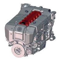
STEYR MOTORS SE236E40 Installation Manual (224 pages)
4 Cylinder / 6 Cylinder
Brand:
STEYR MOTORS
| Category:
Engine
| Size: 11 MB
Table of Contents
Table of Contents
8
Exhaust Gas
32
S 16.2 Sticker Overview 6 Cylinder Engine
42
S 16.3 Sticker Overview 4 Cylinder Engine
43
General Information on Installation
45
Model and Serial Numbers
45
Serial Number 6 Cylinder Engine
45
Serial Number 4 Cylinder Engine
46
Serial Number Gear Box
46
Technical Data and Overview
48
Technical Data 6 Cylinder Engine (from Year of Manufacture 2021)
48
Technical Data 6 Cylinder Engine
49
Overview 6 Cylinder Engine
51
Dimensions 6 Cylinder Engine
54
Technical Data 4 Cylinder Engine (from Year of Manufacture 2021)
55
Overview 4 Cylinder Engine
56
Dimensions 4 Cylinder Engine
59
Sensors and Actuators Overview
60
Weight-Distribution Balance
61
Displacement of Water
63
Conversion Table si - US
67
General Notes on Safety
70
Guidelines for Damage Prevention
70
Legal Rules
70
Safety in the Use of Operating Material
71
How to Select Fuel
73
Transport and Storage
77
Concerning Packing
79
Handling Packing Materials
79
Storage Conditions
82
Start-Up after Storage
83
Preservation
84
St Preservation Procedure
85
Nd Preservation
91
Preservation
92
Preservation Procedure
93
Quality Directives for Assembly
95
Plug Connections for Steel Tube
97
Plug Connection for Plastic Tube
98
Checking of Plug Connections
98
Assembly of Raufoss Plug Systems
98
Sealing of Screwed Pipe Joints
99
Tightening Torques
99
Pipe Relaying
100
Tightening Torques for Electrical Connections
104
General Directions for Use of Anaerobic Sealing Materials
107
Variants Engine Propulsion
109
Bobtail - Version
109
Down Angle
109
Lifeboat Engine
110
Jet Drive
111
Stern Drive
112
Bobtail - Version
113
Down Angle
113
Lifeboat Engine
114
Jet Drive
115
Stern Drive
116
Engine Installation
119
Coupling
120
Universal Joint Shafts
121
Additional Cooling Circuit on Engine
122
Engine Base on Synthetic Boats
122
Dimensions
134
Propeller Pitch
135
Blade Surface
135
Sense of Rotation
135
Number of Blades
136
Axle Hub
136
Adjustment of Propeller Pitch
136
Space between Propeller and Boat
137
Sediments
137
Choice of Propeller
137
Cavitation
139
Cooling System
141
Standard Gear Box Cooling from Steyr Motors
145
Keel Cooling Dimensioning
150
Fuel System
151
Exhaust System
159
Exhaust for Inboard Engines above Water Line
162
Exhaust for Inboard Engines below Water Line
163
Exhaust for Stern Drive Engines
165
Wet Exhaust Pipe
166
Measuring of Back Pressure
169
Air Intake and Ventilation
171
External Consumers
177
Safety Instructions
179
Bilge Pumps
181
Cabin Heating
183
Noise Attenuation
185
Control Station
189
Mechanical Control
191
Hydraulic Control
191
Electronic Control
192
Kinds of Control Levers
194
Possible Functions of Control Lever
194
Scheme for Instrument Panel and SCC2
197
Scheme for Instrument Panel and SCC2 with GPS
198
Cut out Drawing for Instrument Panel (Standard) / Instrument Panel SOLAS
199
Cut out Drawing for SCC Key Ignition Panel/Push Button Ignition Panel (SOLAS) 201 17.7.3 Cut out Drawing for SCC2
202
Electrical Equipment
203
Commissioning of Installation
209
Appendix
211
Engine Base Must
213
Engine Mounts
213
Lifting Points
214
Space for Maintenance
214
Engine Angle
215
Air and Ventilation
215
Raw Water
216
Clean Fuel
216
Exhaust System
217
Inboard Installation
218
Stern Drive Installation
219
Propeller Selection
220
Operating and Auxiliary Materials
221
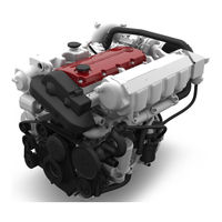
STEYR MOTORS SE236E40 Operation, Maintenance And Warranty Manual (134 pages)
4 + 6 Cylinders
Brand:
STEYR MOTORS
| Category:
Engine
| Size: 24 MB
Table of Contents
Table of Contents
10
General
11
Marine 4 Cyl Engines Overview
12
Marine 6 Cyl Engines Overview
13
Product References, Illustrations and Specifications
15
Insurance
15
Stolen Unit
15
Warranty Registration Approval
15
Dealer Service - Maintenance
16
Illustration Symbols
16
Repair Service
17
Replacement Parts
17
Before Casting off
17
Engine Submersion
18
Bottom Painting
18
Boat Bottom
18
Boating Responsibilities
19
Safety
19
Warning
19
Symbols
20
Table of Contents
22
Before Starting
24
Starting the Engine (Key Switch Version)
25
Stopping the Engine
25
Starting the Engine (Push Button Version)
26
Stopping the Engine (Push Button Version)
26
Definitions
27
Procedure, Work Steps
27
Run in Procedure after Major Overhaul
27
Engine Break-In Procedure
28
Final Ten Hours of Break-In
28
First Ten Hours
28
Operation after Break-In
29
Shifting
30
Remote Control Operating Instructions
31
Fixed Speed Switch
32
Fuel Economy
32
Gear Box - Information
32
How to Shift and Control Speed
32
Instrument Panel (Key Switch Version)
33
Instrument Panel, Standard
33
Instrument Indication During Normal Operation
34
Instrument Panel (Push Button Version)
35
Instrument Indication During Normal Operation (Push Button Version)
36
Emergency Cut off Switch (Lanyard)
37
Warning Lights and Audible Alarm
38
Electronic Engine Control Unit (ECU)
39
Diagnostic System
40
Optional Propellers
41
Propellers
41
Twin Installations
41
High Altitude Operation
42
Operating Procedure for Freezing Temperatures
42
Propeller Care
42
Propeller Torque
42
Salt Water Operation
42
Water Jet
42
Fuel Contamination
43
Fuel Pump
43
Fuel System Checks
43
Cooling System
44
Alternator
46
Battery
46
Electrical Equipment
46
Circuit Breakers & Fuses 4 Cylinder Marine Engine
47
Circuit Breakers & Fuses 6 Cylinder SE Marine Engine
47
Instrument Panel
48
Interrupt Crankshaft Housing Ventilation (Optional)
48
Inversion Switch (Optional)
48
Table of Contents
50
Filter Maintenance & Service
51
Fuel Requirements
51
How to Select Fuel
51
Engine Lubrication
52
Engine Oil
52
Oil Identification Symbol
52
Disposal of Automotive Waste Products
53
Table of Contents
54
Model and Serial Numbers
55
Technical Data and Overview MO84K32, MO94K33, MO114K33
56
Technical Data and Overview MO144M38, MO164M40, MO174V40
58
Technical Data and Overview SE164E40, SE144E38
60
Technical Data and Overview SE-Engines
62
Table of Contents
64
Foreword
66
Important Note
66
MO Service- and Maintenance Schedule
67
SE Service- and Maintenance Schedule
70
SE Service- and Maintenance Schedule
73
Maintenance Log
76
Principle Service Code List "SE" Engines
82
Principle Failure Code List "MO" Engines
86
Trouble Check Chart
88
Wiring Harness 4-Cylinder "MO" Engines
90
Wiring Diagram MO 12 V, 4-Cyl
91
Wiring Diagram MO 24 V, 4-Cyl
92
Wiring Diagram MO 12 V, 2 Pol, 4-Cyl
93
Wiring Diagram MO 24 V, 2 Pol, 4-Cyl
94
Wiring Diagram MO E-Box External, 4-Cyl
95
Wiring Diagram MO E-Box External, 2-Pol, 4-Cyl
96
Wiring Diagram MO 12 V, 6-Cyl
97
Wiring Diagram MO 12 V, 2 Pol, 6-Cyl
98
Wiring Diagram MO 24 V, 2 Pol, 6-Cyl
99
Description - Wiring Harness Instrument Panels 4 Cyl. Marine Engines
100
Wiring Diagram SE E-Box 12V, 6 Cyl
101
Wiring Diagram SE E-Box 24V, 6 Cyl
102
Wiring Diagram External SE E-Box, 6 Cyl
103
Wiring Diagram SE E-Box 12 V, 4 Cyl
104
Wiring Diagram External SE E-Box 12 V, 4 Cyl
105
Wiring Diagram Instument CAN Panel 12/24V
106
Wiring Diagram Instument CAN Panel Solas 12/24V
107
Table of Contents
108
Check Engine Oil Level
109
Oil Level for Power Steering
109
Oil Level for Transmission
109
Refill Engine Oil
109
Check Coolant (Closed Cooling Circuit)
110
Check Raw Water Connection
111
Drain the Raw Water Circuit of the Engine
111
Drain the Cooling Water Circuit of the Engine
112
Cooling System Anodes
113
Anti-Corrosion Anodes
114
Propeller Selection
117
Preparations for Off-Season Storage
118
Start-Up after Storage
118
Limited Engine Warranty/Warranty Registration Approval
122
Limited Engine Warranty
123
Products Warranted
123
What You Must Do to Activate the Warranty
123
Base Engine Warranty
124
Extended Major Components Warranty
126
Summary of Warranty Coverage
127
Additional Coverage for Parts Replaced or Repaired under Warranty
127
Warranty Coverage for Genuine Spare Parts
127
Conditions of Warranty Coverage
127
Limitations and Exclusions
129
Procedure for Making a Warranty Claim
130
Venue and Applicable Law
131
Miscellaneous
131
If You Do Not Receive Satisfactory Warranty Service
131
Warranty Registration Approval
132
Advertisement
STEYR MOTORS SE236E40 Operation, Maintenance And Warranty Manual (120 pages)
Brand:
STEYR MOTORS
| Category:
Engine
| Size: 11 MB
Table of Contents
Table of Contents
5
Start-Up and Functions
4
Fuel and Lubricants
4
Technical Data
4
Table of Contents
5
General
6
Marine Engine Overview
7
Product References, Illustrations and Specifications
13
Insurance
13
Stolen Unit
13
Owner Identification Card
13
Installation and Pre-Delivery Inspection Log
14
Dealer Service - Maintenance
14
Illustration Symbols
14
Repair Service
15
Replacement Parts
15
Before Casting off
15
Engine Submersion
16
Bottom Painting
16
Boat Bottom
16
Boating Responsibilities
17
Safety
17
Warning
17
Symbols
18
Table of Contents
19
Before Starting
21
Starting the Engine (Key Switch Version)
22
Stopping the Engine
22
Starting the Engine (Push Button Version)
23
Stopping the Engine (Push Button Version)
23
Definitions
24
Procedure, Work Steps
24
Run in Procedure after Major Overhaul
24
Engine Break-In Procedure
25
Final Ten Hours of Break-In
25
First Ten Hours
25
Operation after Break-In
26
Shifting
27
Remote Control Operating Instructions
28
Fuel Economy
29
Gear Box - Information
29
High Altitude Operation
29
How to Shift and Control Speed
29
Instrument Panel (Key Switch Version)
30
Instrument Panel, Standard
30
Instrument Indication During Normal Operation
31
Instrument Panel (Push Button Version)
32
Instrument Indication During Normal Operation (Push Button Version)
33
Emergency Cut off Switch (Lanyard)
34
Warning Lights and Audible Alarm
35
Electronic Engine Control Unit (ECU)
36
Diagnostic System
37
Optional Propellers
38
Propellers
38
Twin Installations
38
High Altitude Operation
39
Operating Procedure for Freezing Temperatures
39
Propeller Care
39
Propeller Torque
39
Salt Water Operation
39
Water Jet
39
Fuel Contamination
40
Fuel Pump
40
Fuel System Checks
40
Cooling System
41
Alternator
43
Battery
43
Electrical Equipment
43
Circuit Breakers & Fuses 4 Cylinder Marine Engine
44
Circuit Breakers & Fuses 6 Cylinder SE Marine Engine
44
Dry Operation
45
Instrument Panel
45
Interrupt Crankshaft Housing Ventilation
45
Inversion Switch
45
Table of Contents
47
Filter Maintenance & Service
48
Fuel Requirements
48
How to Select Fuel
48
Engine Lubrication
49
Motor Oil
49
Oil Identification Symbol
49
Disposal of Automotive Waste Products
50
Table of Contents
51
Model and Serial Numbers
52
Technical Data and Overview MO54NA33
53
Technical Data and Overview MO84K32, MO94K33, MO114K33
55
Technical Data and Overview MO144M38, MO164M40, MO174V40
57
Technical Data and Overview SE-Engines
59
Table of Contents
61
Foreword
63
Important Note
63
Owner Service Log
63
Service- and Maintenance Schedule
64
Maintenance Log
67
Table – Error Indication on Instrument Panel
69
Table – Error Indication on Instrument Panel (for Solas Only)
71
Indication and Cancellation of Memorised Sensor and Circuit Faults
73
Selection and Clearing of Stored Service Codes
73
Principle Service Code List
74
Trouble Check Chart
79
Wiring Harness 4-Cylinder Engine
81
Wiring Diagram/Marine Base - 4 Cylinder - 12 V
82
Wiring Diagram/Marine - 4 Cylinder - 2-Pole - 12 V (Option)
83
Wiring Diagram/Marine - 4 Cylinder - 24 V (Option)
84
Wiring Diagram/Marine - 4 Cylinder - 2-Pole - 24 V - Complete System
85
Description - Wiring Harness Instrument Panels 4 Cyl. Marine Engines (Current Version)
86
Wiring Diagram/Instrument Can Panel - 4 & 6 Cylinder - 12 V
87
Wiring Diagram/Instrument Can Panel - 4 & 6 Cylinder - 24 V (Option)
88
WIRING DIAGRAM/INSTRUMENT CAN PANEL - 4 & 6 CYL. - Solas - 12 V (OPTION)
89
Table of Contents
93
Check Motor Oil Level
94
Oil Level for Power Steering
94
Oil Level for Transmission
94
Refill Motor Oil
94
Check Coolant (Closed Cooling Circuit)
95
Check Raw Water (Open Circuit with Pump)
96
Drain the Raw Water Circuit of the Engine
96
Anti-Corrosion Anodes
97
Cooling System Anodes
97
Air Filter
98
Engine Alignment
98
Maintainance Poly - V - Belt Resp. Serpentine Belt
98
Propeller Selection
100
STEYR MOTORS - Dealer - Check-List
101
Commissioning Report
103
Preparations for Off-Season Storage
105
Start-Up after Storage
105
Engine Log
106
Table of Contents
109
STEYR MOTORS - Marine Engines - LIMITED ENGINE WARRANTY
110
What You Must Do to Activate the Warranty
110
Extended Major Components Warranty
112
Additional Coverage for Parts Replaced or Repaired under Warranty
113
Conditions of Warranty Coverage
113
Summary of Warranty Coverage
113
Warranty Coverage for Genuine Spare Parts
113
Limitations and Exclusions
114
Procedure for Making a Warranty Claim
115
Miscellaneous
116
Venue and Applicable Law
116
If You Do Not Receive Satisfactory Warranty Service
117
Engine, Gearbox, Boat Model and Hull Identification Numbers
118
Steyr Owner Identification Card
119
Service Network
120
Advertisement
Related Products
STEYR MOTORS SE236S36
STEYR MOTORS SE266E40
STEYR MOTORS SE266S36
STEYR MOTORS SE286E40
STEYR MOTORS SE126E25
STEYR MOTORS SE156E26
STEYR MOTORS SE196E35
STEYR MOTORS SE144E38
STEYR MOTORS SE156E32
STEYR MOTORS SE156E34
STEYR MOTORS Categories
Engine
Test Equipment
More STEYR MOTORS Manuals
Login
Sign In
OR
Sign in with Facebook
Sign in with Google
Upload manual
Upload from disk
Upload from URL