Sign In
Upload
Manuals
Brands
Staubli Manuals
Controller
CS8C
Staubli CS8C Manuals
Manuals and User Guides for Staubli CS8C. We have
1
Staubli CS8C manual available for free PDF download: Instruction Manual
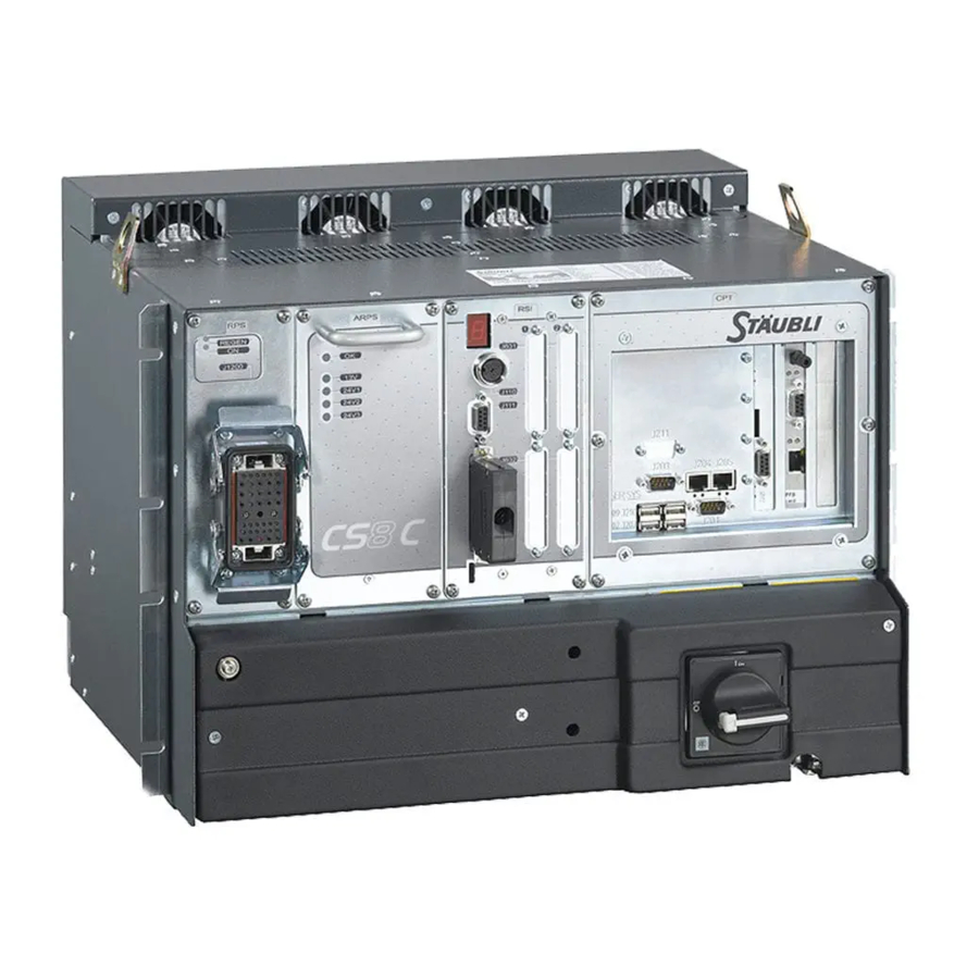
Staubli CS8C Instruction Manual (249 pages)
Brand:
Staubli
| Category:
Controller
| Size: 9 MB
Table of Contents
Table of Contents
3
1 Introduction
9
Special Messages Concerning Warnings, Alerts, and Information
11
Foreword
11
Definition of the Elements Around the Robot Cell
12
2 Description of the Controller
15
Identification
17
Standard Version
17
UL Version
17
Location and Description of the Main Components
18
The Controller
18
The MCP (Manual Control Pendant)
19
WMS Front Panel
19
Safety
21
3 Safety
23
Reminder Concerning the Safety Standards
23
Safety Directives Concerning to the Work Environment
25
Analysis of Safety Around the Robot Cell
25
Rules Concerning the Robot's Work Area
25
Safety Directives Concerning to Staff Protection
26
Mechanical and Electrical Dangers
26
Robot Cell Safety Devices
27
Safety Directives Concerning to Protection of the Equipment
28
Connections
28
Information on Electrostatic Discharges
28
Typical ESD Voltages
29
Prevention of Damage Due to Electrostatic Discharges
30
4 Installation
33
Robotized Cell Environment
35
Positive Safety
35
Power Sources
35
On-Site Preparation
36
Electrical Network
36
Pneumatic Network
37
Work Environment
37
Controller Foot Print and Fittings
38
CS8C for TX and RS Arms
38
CS8C for RX160 Arm
39
Air Circulation
40
Accessibility
40
Unpacking and Handling
41
Packaging for the CS8C Controller
41
Handling of Packing
41
Unpacking and Installing the Controller
41
Fixing the MCP
42
Characteristics
42
Holder Measurements
43
Fixing the WMS
44
WMS Overall Dimensions
45
Connection to the Mains Power Supply
46
Connection between the Arm and the Controller
48
Connecting the Signals
49
Cable Inlets and Outlets
50
Integration
53
Composition of the Emergency and Safety Stop Channels
55
Emergency and Safety Stop Channels
55
Emergency Stop Channels
57
Connection with Cell
61
Basic Inputs/Outputs
62
User-In Inputs
62
Fast Inputs/Outputs
63
Connection Point Table
64
Two Encoder Inputs for STARC2
66
Recovery Procedure (Preset)
67
Position Capture Procedure
68
Position Reading
68
Arm Temperature Thresholds
69
CPU Board Temperature
69
Power Supply for the Controller
69
System Inputs
69
Installation of the Option
70
RS Robots
70
Installation of Can Board in Computer
71
Installation of Cable
72
Installation of I/O Board in the Arm
72
Procedure for Connecting the Inputs/Outputs in the Forearm
72
Software Setup
72
Connecting the Inputs/Outputs to the Tool Interface (Option)
73
CIO Board
74
Analog Inputs
75
Digital Inputs
75
Digital Ouputs
75
Hardware Configuration
76
Armio Board
78
Connections on the Tool Interface
82
AS-I Digital Inputs/Outputs (RS Arms)
83
Configuration
83
Description
83
BIO 16I/16O Board Description
84
Digital Bio Input/Output Board (Optional Extra)
84
Characteristics of the BIO Inputs
85
BIO Board-Inputs
86
Characteristics of the BIO Outputs
87
BIO Board-Outputs
88
Installation of the BIO Option
90
Installing the First Board
90
Installing the Second Board
90
Defining the Field Bus Configuration (Applicomio)
91
Field Bus
91
Preparation of the Configuration (CS8C)
91
Remote Creation of a Configuration (Applicomio)
91
Checking the Configuration (CS8C)
92
CS8C Configuration (Applicomio)
92
Diagnosis
92
The Applicomio Diagnoses Are
93
Operation in the CS8C Controller
96
PLC Cycle
96
Programmable Logic Controller (PLC Option)
96
Starting
96
CPU Load
97
Interaction with the VAL3 Program
97
Overrun Error
97
PLC Utility for the MCP
97
Definition of the Inputs/Outputs
98
PLC Programming in SRS
98
The CS8C Parameters of the PLC Option Are
98
Archiving the PLC Program
100
Downloading a PLC Program
100
Ethernet Link
101
FTP Protocol
101
Modbus TCP Protocol
101
The CS8C Diagnoses Are
102
Ethernet Sockets (TCP)
103
Serial Ports
104
5.10. Software Configurations
105
Configuration of the Controller Characteristics
105
Language Configuration
105
Configuration of the Arm Characteristics
106
Configuration of the User Profiles
107
Configuration of System Inputs/Outputs
108
Access to the System Statuses and Signals
109
Configuration for the "Remotemcp" Option
110
Operation
113
Powering up the Controller
115
General Presentation
116
Presentation of the MCP
116
Leds and Luminous Indicator Keys
117
Control Keys
120
Information and Help Keys
121
Navigation Keys
121
MCP Display
123
Menus
123
Status Bar
123
The Work Page
123
Drop down Lists
124
Entry Boxes
124
ARM Power-Up
125
Emergency Stop
126
Restarting
126
Calibration, Adjustment, Recovery
127
Recovery Procedure
127
Adjustment Procedure
128
Local Mode
129
Manual Mode
129
Working Mode
129
Remote Mode
130
Jog Interface
131
Presentation
131
Description of the Jog Interface Page
132
Movement in Joint Mode (Joint)
134
Movement in Cartesian Mode (Frame, Tool)
135
Specific Case (Arm RS)
135
Movements in Point Mode
137
Starting an Application
138
Starting up in Local Mode
138
Starting up in Manual Mode
139
Starting up in Remote Mode
139
Movements on Restarting
140
Stopping Using the Powering Up/ Power Switch-Off Button
140
Stopping/Starting Movements Using the Move/Hold Key
140
Stopping Movements Via the Emergency Stop Button
141
Stopping/Starting Movements Using the Stop Key
141
6.10. Val3 Application Manager
142
Closing/Deleting an Application
142
Opening an Existing Application
142
Operations Concerning Applications
142
Exporting a VAL3 Application
143
Online Commands
143
Opening Mode for an Application
143
Saving a VAL3 Application
143
Library, Data, Program Creation and Edition
144
Modifying an Application
144
Program Editor
144
Debugging an Application
147
Input/Output Status
148
Methods for Diagnosis
148
System Events
148
Task Status
148
6.11. Teaching Frames
150
6.12. Teaching Points
151
6.13. Motion Descriptor Editor
152
6.14. Controller Backup
152
PC Utilities
155
Functionalities
157
Stäubli Robotics Studio (Srs)
157
FTP Access from a PC
158
FTP Client
158
Functions Via FTP
158
IP Address Configuration
158
FTP Access to a PC
159
Installing Cesar FTP
160
Maintenance
163
How to Use this Manual?
165
Intervention Levels
165
Safety Recommendations
165
Service Methodology
165
Glossary
166
Component Location
167
Safety
168
Input Voltage
169
Access
170
Case 1
171
Trouble Shooting
171
Case 2
172
Case 3
175
Arps Auxiliary Robot Power Supply
176
Test Points
177
Access to Fans
179
Advanced Information
182
Alim-Ok Signal
187
Secteur_Ok Signal
189
Brk_X Signals
191
RPS Power Supply
194
CS8C for TX or RS Robots
195
CS8C for RX160 Robots
197
Rsi
203
Error Codes on 7-Segment Display
209
Starc Board
232
Optical Fiber
237
Dsi
238
Common Lines for All Encoders
239
DSI Advanced Information
239
Individual Lines
239
Preventive Maintenance
242
Ventilation
242
Recommended Spare Parts
242
Protection of the Power Line for the CS8C Controller
247
Appendix: Protection of the Power Line for the Cs8C
247
Controller Characteristics
247
Protection Upstream from the Controller
247
You Need to Install One of the Following
248
Choice of the Protection
248
Protection against Surges
248
Protection against Short-Circuits
248
Advertisement
Advertisement
Related Products
Staubli CombiTac direqt
Staubli CombiTac uniq CT-E1,5-4/HV-B
Staubli CombiTac uniq CT-E1,5-4/HV-S
Staubli CombiTac uniq CT-E3-1/HV-B
Staubli CombiTac uniq CT-E3-2/HV-B
Staubli CombiTac uniq CT-E3-1/HV-S
Staubli CombiTac uniq CT-E3-2/HV-S
Staubli CombiTac uniq CT-BP1,5/0,5-1,5-HV
Staubli CombiTac uniq CT-BP3/2,5-HV AU
Staubli CombiTac direqt SMA
Staubli Categories
Cables and connectors
Crimp tool
Power Tool
Tools
Industrial Equipment
More Staubli Manuals
Login
Sign In
OR
Sign in with Facebook
Sign in with Google
Upload manual
Upload from disk
Upload from URL