Sign In
Upload
Manuals
Brands
ST Manuals
Motherboard
STSW-S2LP-KNX-DK
User Manuals: ST STSW-S2LP-KNX-DK Software Package
Manuals and User Guides for ST STSW-S2LP-KNX-DK Software Package. We have
1
ST STSW-S2LP-KNX-DK Software Package manual available for free PDF download: User Manual
ST STSW-S2LP-KNX-DK User Manual (71 pages)
Brand:
ST
| Category:
Motherboard
| Size: 9 MB
Table of Contents
1 Getting Started
2
Overview
2
Folder Structure
2
Hardware Configurations
2
Steval-Idb008V2
2
Figure 1. STSW-S2LP-KNX-DK Folder Structure
2
Figure 2. STEVAL-IDB008V2 Evaluation Board
3
Figure 3. CN3 Modifications
3
Nucleo-L073Rz
4
Figure 4. CN4 Modifications
4
X-NUCLEO-S2868A1 and X-NUCLEO-S2868A2
5
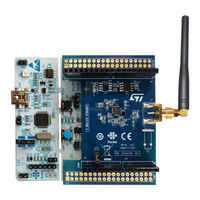
Figure 5. NUCLEO-L073RZ Development Board
5
Figure 6. X-NUCLEO-S2868A1 Expansion Board
5
Software Requirements
6
Keil Μvision
6
Figure 7. X-NUCLEO-S2868A2 Expansion Board
6
Figure 8. MDK-ARM Download Web Page
7
Figure 9. MDK-ARM Device Support Packs
7
Figure 10. MDK-ARM License Activation for Cortex-M0/M0
8
Knx Ets5
9
Bluenrg-X Flasher Utility
9
Figure 11. Procedure to Activate Free Keil License
9
Figure 12. ETS5 Lite Demo Download
9
Stm32Cubeprogrammer
10
Dedicated Android Apps for BLE Connectivity
10
Figure 13. Bluenrg-X Flasher Utility Installation
10
Figure 14. Stm32Cubeprogrammer Installation
10
Alternative Apps for BLE Connectivity
11
Figure 15. Light Control App
11
Figure 16. APK File Location
11
Figure 17. BLE Scanner App
12
2 KNX-RF Evaluation Package Options
13
Package Overview
13
KNX-RF Frameworks Based on Bluenrg-2 BLE 5.1 System-On-Chip
13
Figure 18. KNX-RF Framework Based on Bluenrg-2
13
KNX-RF Frameworks Based on STM32L0 Microcontroller
14
KNX-RF Point-To-Point Topology Based on Bluenrg-2 Evaluation Kits
14
KNX-RF Point-To-Point Topology Based on STM32L0 Development Boards
14
Figure 19. KNX-RF Framework Based on STM32L0 Microcontroller
14
Figure 20. Point-To-Point Topology Based on Bluenrg-2 Evaluation Kits (STEVAL-IDB008V2)
14
ETS Connectivity through KNX RF/TP Gateway Based on Bluenrg-2 Evaluation Kits
15
ETS Connectivity through KNX RF/TP Gateway Based on STM32L0 Development Boards
15
Figure 21. Point-To-Point Topology Based on STM32L0 Development Boards (NUCLEO-L073RZ)
15
Figure 22. ETS Connectivity Based on Bluenrg-2 Evaluation Kits
15
ETS Connectivity through USB Dongle Based on Bluenrg-2 Evaluation Kits
16
Figure 23. ETS Connectivity Based on STM32L0 Development Boards
16
Figure 24. ETS Connectivity through USB Dongle Based on Bluenrg-2 Evaluation Kits
16
ETS Connectivity through USB Dongle Based on STM32L0 Development Boards
17
Figure 25. ETS Connectivity through USB Dongle Based on STM32L0 Development Boards
17
3 Point-To-Point KNX-RF Communication Setup
18
Bluenrg-2 Setup
18
Hardware Setup
18
Software Setup
18
Figure 26. S2-LP and Bluenrg-2 Stack Plus Antennas
18
Figure 27. Selecting the COM Port
19
Figure 28. Mass Erase
19
Figure 29. Hex Files
19
Figure 30. STSW-BNRGFLASHER Procedure
20
Figure 31. Topology for Hex Files
20
Figure 32. Tera Term Setup
20
KNX-RF Evaluation Using Dedicated BLE Apps
21
Figure 33. Resetting Tera Term Information
21
Figure 34. Refresh BLE Device Scanning
22
Figure 35. Refresh BLE Device Scanning
22
Figure 36. BLE KNX-RF Push Button Application
23
Figure 37. LED Control Application
24
Figure 38. On/Off Control Example
24
Figure 39. Dimming Control Example
24
KNX-RF Evaluation Using Standard BLE Apps
25
Figure 40. Color Control Using RGB Data Example
25
Figure 41. KNX-RF Enhanced Communication
25
Figure 42. BLE Scanner App
26
Figure 43. Bluenrg2_Knx1 Device Identified
27
Figure 44. Connection of BLE Devices
27
Figure 45. Write Command in Custom Characteristic
28
Figure 46. Switch on Example
28
Figure 47. Switch off Example
29
Figure 48. Dimming Command Example
29
STM32L0 Setup
30
Hardware Setup
30
Figure 49. Color Command Example
30
Software Setup
31
Figure 50. S2-LP and STM32L0 Stack Plus Antenna
31
Figure 51. Connecting the Development Board Via Stm32Cubeprogrammer
32
Figure 52. Full Chip Erase and Binary File Download
32
Figure 53. Topology for the Binary Files
33
Figure 54. LED Actuator Setup
33
Figure 55. LED Actuator Setup
33
Figure 56. KNX-RF Switch Application Setup
34
KNX-RF Evaluation Using STM32 Nucleo Development Boards
35
Figure 57. Messages Displayed after Board Reset
35
Figure 58. Switch On/Off Commands
35
Figure 59. Dimming Command
36
Figure 60. Color Command
36
4 ETS5 KNX-RF Communication Setup
37
ETS5 Setup through Tapko RF/TP Coupler
37
KNX-RF Topology
37
Figure 61. Bluenrg-2 Based Setup
37
Required KNX-RF Devices
38
Figure 62. STM32L0 Based Setup
38
Figure 63. Mecrf - KNX-RF Media Coupler
38
Start ETS Project
39
Figure 64. KNX Bus Power Supply
39
Figure 65. KNX Bus Power Supply
39
Figure 66. Importing ETS Projects
40
Figure 67. Selecting the Project
40
Figure 68. Entering the Project Password
40
Figure 69. Configuring the USB Interface
41
Figure 70. Opening the ETS Project
41
ETS Project Overview
42
Addressing KNX Devices
42
Figure 71. Checking the USB Interface
42
Figure 72. KNX System Topology
42
ETS Group Monitor
43
Figure 73. Push Button Application
43
Figure 74. LED Actuator Application
43
Figure 75. Dummy Device Configuration
43
ETS Evaluation with Bluenrg-2 Devices
44
Figure 76. Group Monitor
44
Figure 77. TP/RF Device Full Download
44
Figure 78. Programming Button
44
Group Monitor
44
Figure 79. Bluenrg-2 Board PUSH2 Button
45
Figure 80. KNX-RF Activity Transfer
45
Figure 81. Press Programming Button Message
45
Figure 82. Bluenrg-2 Board Leds
46
Figure 83. Push Button Application Download
46
Figure 84. Push Button Application Download Completed
46
ETS Evaluation with STM32L0 Devices
47
Figure 85. RESET Button
47
Figure 86. ETS Monitoring Activity
47
Figure 87. ETS Log Analysis
47
Figure 88. ETS Project Topology
48
Figure 89. ETS Full Download
48
Figure 90. Press the Programming Button Message
48
ETS5 Setup through Tapko USB Dongle
49
KNX-RF Topology
49
Figure 91. Starting the Download
49
Figure 92. KNX-RF Communications During ETS Download
49
Figure 93. KNX-RF Communication Monitoring
49
Figure 94. Bluenrg-2 Based Setup
50
Figure 95. STM32L0 Based Setup
50
Required KNX-RF Devices
51
Start ETS Project
51
Figure 96. Uimrf - KNX USB Interface
51
Figure 97. Importing ETS Projects
51
Figure 98. Selecting the Project
51
Figure 99. Entering the Project Password
52
Figure 100
52
Topology Panel and Domain Address
52
ETS Project Overview
53
Addressing KNX Devices
53
Figure 102
53
KNX System Topology
53
ETS Group Monitor
54
Figure 105. LED Actuator Application
54
ETS Evaluation with Bluenrg-2 Devices
55
Figure 107
55
Figure 110. Press Programming Button Message
56
Figure 111
56
Bluenrg-2 Board Leds
56
Figure 112. Push Button Application Download
56
Figure 113
56
ETS Evaluation with STM32L0 Devices
57
RESET Button
57
ETS Monitoring Activity
57
ETS Log Analysis
57
Figure 117. ETS Project Topology
58
Figure 118. ETS Full Download
58
Figure 119. Press the Programming Button Message
58
Figure 120. Starting the Download
58
Alert Message
59
KNX-RF Communications During ETS Download
59
KNX-RF Communication Monitoring
59
Figure 124
60
Figure 125. Failed Download
60
5 KNX-RF Software Package
61
KNX-RF Package Structure
61
KNX-RF Project Examples
61
Keil Project Structure
61
Keil Project Examples
61
Figure 128
62
Figure 129. Bluenrg-2 Application
62
Figure 130. STM32L0 Application
62
Keil Project Debug
63
Figure 131
63
Figure 132
63
Figure 133
63
Revision History
64
Table of Contents
65
Contents
65
List of Tables
67
List of Figures
68
Advertisement
Advertisement
Related Products
ST STSW-STUSB002
ST STSW-GLA001V1
ST STSW-IDS002V1
ST STSW-ROBKIT1
ST STM32F439 Series
ST ST9 EPB
ST STEVAL-PCC008V1
ST STEVAL-BTDP1
ST STEVAL-ICB008V1
ST STM32F46I-DISCO
ST Categories
Motherboard
Computer Hardware
Microcontrollers
Control Unit
Controller
More ST Manuals
Login
Sign In
OR
Sign in with Facebook
Sign in with Google
Upload manual
Upload from disk
Upload from URL