Sign In
Upload
Manuals
Brands
ST Manuals
Microcontrollers
STM32H7B3I-DK
ST STM32H7B3I-DK Development Kit Manuals
Manuals and User Guides for ST STM32H7B3I-DK Development Kit. We have
2
ST STM32H7B3I-DK Development Kit manuals available for free PDF download: User Manual
ST STM32H7B3I-DK User Manual (53 pages)
Brand:
ST
| Category:
Microcontrollers
| Size: 7 MB
Table of Contents
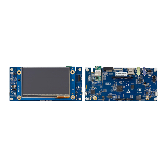
Figure 1. STM32H7B3I-DK Top View
1
Figure 2. STM32H7B3I-DK Bottom View
1
Features
2
Ordering Information
3
Codification
3
Table 1. Ordering Information
3
Table 2. Codification Explanation
3
Development Environment
4
System Requirements
4
Development Toolchains
4
Demonstration Software
4
Conventions
5
Table 3. ON/OFF Convention
5
Delivery Recommendations
6
Getting Started
7
Hardware Layout and Configuration
8
Figure 3. STM32H7B3I-DK Hardware Block Diagram
8
Figure 4. STM32H7B3I-DK PCB Layout (Top View)
9
Figure 5. STM32H7B3I-DK PCB Layout (Bottom View)
9
Figure 6. STM32H7B3I-DK Board Mechanical Dimensions (Top View, in Millimeters)
10
Figure 7. STM32H7B3I-DK Board Mechanical Dimensions (Bottom View, in Millimeters)
10
Embedded STLINK-V3E
11
Description
11
Drivers
11
Figure 8. USB Composite Device
11
STLINK-V3E Firmware Upgrade
12
Using an External Debug Tool to Program and Debug the Onboard STM32
12
Table 4. CN8 MIPI-10 Debug Connector
12
Figure 9. Connecting an External Debug Tool to Program the Onboard STM32H7B3I-DK
12
Power Supply
13
Supplying the Board through STLINK-V3E USB Connector 5 V / 500 Ma
13
Supplying the STM32H7B3I-DK Using the External Power Supply Input from VIN (7 to 12 V, 800Ma Max)
14
Supplying the STM32H7B3I-DK Using a USB Charger (5 V)
14
Supplying the STM32H7B3I-DK Using USB OTG HS Connector (5 V / 500 Ma)
14
Table 5. External Power Sources: VIN (7 to 12 V)
14
Table 6. External Power Source: CHGR (5 V)
14
Table 7. External Power Source: U5V (5 V)
14
MCU Power Supply - SMPS/LDO Configuration
15
Figure 10. MCU Power: SMPS/LDO
15
Figure 11. Config1 - LDO Only
16
Figure 12. Config2 - SMPS Only (Default)
16
Table 8. Internal SMPS / LDO and Board Configuration
17
Figure 13. Config3 - SMPS and LDO Cascaded
17
Figure 14. Config4 - External SMPS
17
Measurement of MCU Current Consumption
18
Clock Source
18
Reset Sources
19
Board Functions
19
TFT Color LCD 480X272 Pixels
19
Usb Otg Hs
19
Ext_I2C
19
Microsd ™ Card
19
Audio
20
Can Fd
20
Octo-SPI nor Flash Memory
20
SDRAM Memory
20
Table 9. FD-CAN1 - Solder Bridge Configuration
20
Virtual COM Port
21
Tag
21
Buttons and Leds
21
Table 10. Button and LED Control Port
21
Wi-Fi ® RF Module
22
Figure 15. Wi-Fi ® Module (Top View)
22
Table 11. Wi-Fi ® - Solder Bridge Configuration
23
Board Connectors
24
CN14 STLINK-V3E USB Micro-B Connector
24
Table 12. CN14 USB Micro-B Connector Pinout
24
Figure 16. CN14 Micro-B Connector (Front View)
24
CN15 USB OTG HS Micro-AB Connector
25
Table 13. CN15 USB OTG HS Micro-AB Connector Pinout
25
Figure 17. CN15 USB OTG HS Micro-AB Connector (Front View)
25
CN4 Microsd ™ Card Connector
26
Table 14. CN4 Microsd ™ Connector Pinout
26
Figure 18. CN4 Microsd ™ Card Connector
26
P1 Stmod+ Connector
27
Table 15. P1 Stmod+ Connector Pinout
27
Figure 19. P1 Stmod+ Connector
27
CN7 Camera Module Connector
28
Figure 20. CN7 Camera Module Connector
28
CN12 TAG Connector
29
CN16 EXT_I2C Connector
29
Table 16. CN7 Camera Module Connector Pinout
29
Table 17. CN12 TAG Connector Pinout
29
Figure 21. CN12 TAG Connector
29
CN3 Audio Connector
30
Table 18. CN16 EXT_I2C Connector Pinout
30
Table 19. I2C4 Onboard Addresses
30
Table 20. DFSDM - Solder Bridge Configuration
30
Figure 22. CN16 EXT_I2C Connector
30
Table 21. CN3 Audio Connector Pinout
31
Figure 23. CN3 Audio Connector
31
CN1 TFT LCD Connector
32
Table 22. CN1 TFT LCD Connector
32
Figure 24. CN1 TFT LCD Connector
32
CN10, CN11, CN19, and CN20 ARDUINO ® uno V3 Connectors
33
Table 23. ARDUINO ® uno V3 Compatible Connectors Pinout
33
CN5 Audio Green Jack - Line out
34
CN6 Audio Blue Jack - Line in
34
Table 24. CN5 Audio Jack Connector Pinout (Onboard)
34
Table 25. CN5 Audio Jack Connector Pinout (Onboard)
34
Figure 25. CN5 Stereo Headset with a Microphone Jack
34
Figure 26. CN6 Stereo Headset with a Microphone Jack
34
STM32H7B3I-DK Board Information
35
Product Marking
35
STM32H7B3I-DK Product History
35
Product Identification DK32H7B3I$AT1
35
Product Identification DK32H7B3I$AT2
35
Product Identification DK32H7B3I$AT3
35
Product Identification DK32H7B3I$AT4
36
Board Revision History
36
Board MB1332 Revision B-02
36
Board MB1332 Revision C-01
36
Board MB1332 Revision C-02
36
Board MB1315 Revision A-01
36
Board MB1315 Revision A-02
36
Board MB1486 Revision A-02
36
Board MB1486 Revision A-03
36
Board MB1280 Revision A-03
37
Board MB1280 Revision B-01
37
Board MB1280 Revision C-01
37
Appendix Astm32H7B3I-Dk I/O Assignment
38
Table 26. STM32H7B3I-DK I/O Assignment
38
Appendix Bstmod+ GPIO Sharing and Multiplexing
43
Table 27. Stmod+ GPIO Sharing and Multiplexing
44
Appendix C Federal Communications Commission (FCC) and Innovation, Science and Economic Development Canada (ISED) Compliance Statements
45
FCC Compliance Statement
45
ISED Compliance Statement
45
Revision History
47
Table 28. Document Revision History
47
Table of Contents
48
List of Tables
51
List of Figures
52
Advertisement
ST STM32H7B3I-DK User Manual (54 pages)
Discovery kit with STM32H7B3LI MCU
Brand:
ST
| Category:
Microcontrollers
| Size: 7 MB
Table of Contents
Figure 1. STM32H7B3I-DK Top View
1
Figure 2. STM32H7B3I-DK Bottom View
1
1 Features
2
2 Ordering Information
3
Product Marking
3
Codification
3
Table 1. Ordering Information
3
Table 2. Codification Explanation
3
3 Development Environment
4
System Requirements
4
Development Toolchains
4
Demonstration Software
4
4 Conventions
5
Table 3. ON/OFF Convention
5
5 Delivery Recommendations
6
6 Getting Started
7
7 Technology Partners
8
8 Hardware Layout and Configuration
9
Figure 3. STM32H7B3I-DK Hardware Block Diagram
9
Figure 21. CN12 TAG Connector
10
Figure 4. STM32H7B3I-DK PCB Layout (Top View)
10
Figure 5. STM32H7B3I-DK PCB Layout (Bottom View)
10
Figure 6. STM32H7B3I-DK Board Mechanical Dimensions (Top View, in Millimeters)
11
Figure 7. STM32H7B3I-DK Board Mechanical Dimensions (Bottom View, in Millimeters)
11
Embedded STLINK-V3E
12
Description
12
Drivers
12
Figure 8. USB Composite Device
12
STLINK-V3E Firmware Upgrade
13
Using an External Debug Tool to Program and Debug the Onboard STM32
13
Table 4. CN8 MIPI-10 Debug Connector
13
Figure 9. Connecting an External Debug Tool to Program the Onboard STM32H7B3
13
Power Supply
14
Supplying the Board through STLINK-V3E USB Connector 5 V / 500 Ma
14
Supplying the STM32H7B3I-DK Using the External Power Supply Input from VIN (7 to 12 V, 800Ma Max)
15
Supplying the STM32H7B3I-DK Using USB Charger (5 V)
15
Supplying the STM32H7B3I-DK Using USB OTG HS Connector (5 V / 500 Ma)
15
Table 5. External Power Sources: VIN (7 to 12 V)
15
Table 6. External Power Source: CHGR (5 V)
15
Table 7. External Power Source: U5V (5 V)
15
MCU Power Supply - SMPS/LDO Configuration
16
Figure 10. MCU Power: SMPS/LDO
16
Figure 11. Config1 - LDO Only
17
Figure 12. Config2 - SMPS Only (Default)
17
Table 8. Internal SMPS / LDO and Board Configuration
18
Figure 13. Config3 - SMPS and LDO Cascaded
18
Figure 14. Config4 - External SMPS
18
Measurement of MCU Current Consumption
19
Board Functions
20
TFT Color LCD 480X272 Pixels
20
Usb Otg Hs
20
Ext_I2C
20
Microsd™ Card
20
Audio
21
Fd-Can
21
Octo-SPI nor Flash Memory
21
SDRAM Memory
21
Table 9. FD-CAN1 - Solder Bridge Configuration
21
Virtual COM Port
22
Tag
22
Buttons and Leds
22
Table 10. Button and LED Control Port
22
Wi-Fi ® RF Module
23
Figure 15. Wi-Fi ® Module (Top View)
23
Table 11. Wi-Fi ® - Solder Bridge Configuration
24
Clock Source
20
Reset Sources
20
9 Board Connectors
25
CN14 STLINK-V3E USB Micro-B Connector
25
CN15 USB OTG HS Micro-AB Connector
25
Table 12. CN14 USB Micro-B Connector Pinout
25
Figure 16. CN14 Micro-B Connector (Front View)
25
Table 13. CN15 USB OTG HS Micro-AB Connector Pinout
26
Figure 17. CN15 USB OTG HS Micro-AB Connector (Front View)
26
CN4 Microsd™ Card Connector
27
Table 14. CN4 Microsd ™ Connector Pinout
27
Figure 18. CN4 Microsd ™ Card Connector
27
P1 Stmod+ Connector
28
Table 15. P1 Stmod+ Connector Pinout
28
Figure 19. P1 Stmod+ Connector
28
CN7 Camera Module Connector
29
Table 16. CN7 Camera Module Connector Pinout
29
Figure 20. CN7 Camera Module Connector
29
CN12 TAG Connector
30
CN16 EXT_I2C Connector
30
Table 17. CN12 TAG Connector Pinout
30
Figure 22. CN16 EXT_I2C Connector
30
CN3 Audio Connector
31
Table 18. CN16 EXT_I2C Connector Pinout
31
Table 19. I2C4 Onboard Addresses
31
Table 20. DFSDM - Solder Bridge Configuration
31
Figure 23. CN3 Audio Connector
31
Table 21. CN3 Audio Connector Pinout
32
CN1 TFT LCD Display Connector
33
Table 22. CN1 TFT LCD Display Connector
33
Figure 24. CN1 TFT LCD Display Connector
33
CN10, CN11, CN19, and CN20 ARDUINO® uno V3 Connectors
34
Table 23. ARDUINO ® uno V3 Compatible Connectors Pinout
34
CN5 Audio Green Jack - Line out
35
CN6 Audio Blue Jack - Line in
35
Table 24. CN5 Audio Jack Connector Pinout (Onboard)
35
Figure 25. CN5 Stereo Headset with a Microphone Jack
35
Figure 26. CN6 Stereo Headset with a Microphone Jack
35
Table 25. CN5 Audio Jack Connector Pinout (Onboard)
36
Appendix Astm32H7B3I-Dk I/O Assignment
37
Table 26. STM32H7B3I-DK I/O Assignment
37
Appendix B Fanout Board (MB1280)
42
Mikroelektronika Mikrobus™ Compatible Connector (Fanout CN10 / CN11)
42
Table 27. Description of the Mikrobus™ Connector Pins
42
Figure 27. Stmod+ Fanout Board Plugged into CN1 Connector
42
ESP-01 Wi-Fi ® Board Compatible Connector
43
Compatible Connectors for the Grove Boards
43
Compatible Connectors for I C Grove Boards (Fanout CN3)
43
Compatible Connector for UART Grove Boards (Fanout CN2)
43
Table 28. Description of the ESP-01 Wi-Fi ® Connector Pins
43
Table 29. Description of the I C Grove Board CN3 Connector Pins
43
Table 30. Description of the UART Grove Board CN2 Connector Pins
43
Appendix Cstmod+ GPIO Sharing and Multiplexing
44
Table 31. Stmod+ GPIO Sharing and Multiplexing
45
Appendix D Federal Communications Commission (FCC) and Industry Canada (IC)
46
Compliance Statements
46
FCC Compliance Statement
46
IC Compliance Statement
46
Revision History
48
Table 32. Document Revision History
48
Table of Contents
49
Contents
49
List of Tables
52
List of Figures
53
Advertisement
Related Products
ST STM32H750B-DK
ST STM32H723
ST STM32H733
ST STM32H725AG
ST STM32H725RE
ST STM32H725RG
ST STM32H723ZE
ST STM32H723ZG
ST STM32H743 Series
ST STM32H753 Series
ST Categories
Motherboard
Computer Hardware
Microcontrollers
Control Unit
Controller
More ST Manuals
Login
Sign In
OR
Sign in with Facebook
Sign in with Google
Upload manual
Upload from disk
Upload from URL