Sign In
Upload
Manuals
Brands
ST Manuals
Engine
STEVAL-CTM015V1
ST STEVAL-CTM015V1 Manuals
Manuals and User Guides for ST STEVAL-CTM015V1. We have
1
ST STEVAL-CTM015V1 manual available for free PDF download: User Manual
ST STEVAL-CTM015V1 User Manual (44 pages)
Three-Phase Switched Reluctance Motor
Brand:
ST
| Category:
Engine
| Size: 5 MB
Table of Contents
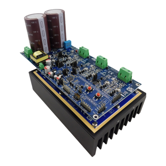
Figure 1. STEVAL-CTM015V1 Evaluation Kit
1
Evaluation Kit Features
2
Getting Started
3
Safety Precautions
3
General Terms
3
Intended Use of Evaluation Kit
4
Evaluation Kit Setup
4
Electronics Connections
4
Table 1. Functioning Electrical End Setup Parameters
4
Electrical Safety
5
Personal Safety
5
Storage of Charge
5
High Temperature and Flammability
5
Dangerous Surface or Edges
5
Electromagnetic Compatibility
6
Figure 2. DC Input Wires - Ferrite Connection
6
Figure 3. Antenna Polarization Horizontal Results
7
Figure 4. Antenna Polarization Vertical Results
7
Evaluation Kit Overview
8
Figure 5. STEVAL-CTM015V1 Block Diagram
8
Figure 6. Main Blocks of the STEVAL$CTM015A1A Drive Board
8
Figure 7. Main Blocks of STEVAL$CTM015A2B Power Board
8
DC Input Voltage
9
Voltage Connection
9
Input Voltage Modes
9
Internal 15 V Mode Selection
9
External 15 V Mode Selection
9
Figure 8. Internal 15 V Mode Activation Details
9
Figure 9. External 15 V Mode Activation Details
9
DC-Link Voltage Range
10
Motor Terminals Connection
10
Push Buttons
10
Switch Mode Selection
10
Speed/Position Sensor
10
Table 2. Jumper Configuration
10
Figure 10. CN10 Connector Position Sensor
10
LED Diodes Descriptions
11
STLINK V3 Debugger and Programmer Connection (CN1)
11
Table 3. Sensor Supplying Voltage Selection
11
Figure 11. STLINK V3 Connector (CN1)
11
Default Firmware
12
Figure 12. Phase Currents - Oscilloscope Capture
12
Test Reports
13
Temperature Measurements
13
Figure 13. Temperature Measurements at 420W, 400V
13
Table 4. Temperature Measurements at 1000 W of Power Board STEVAL-CTM015A2
14
Schematic Diagrams
15
Figure 14. STEVAL-CTM015A1 Circuit Schematic (1 of 12)
15
Figure 15. STEVAL-CTM015A1 Circuit Schematic (2 of 12)
16
Figure 16. STEVAL-CTM015A1 Circuit Schematic (3 of 12)
17
Figure 17. STEVAL-CTM015A1 Circuit Schematic (4 of 12)
18
Figure 18. STEVAL-CTM015A1 Circuit Schematic (5 of 12)
19
Figure 19. STEVAL-CTM015A1 Circuit Schematic (6 of 12)
20
Figure 20. STEVAL-CTM015A1 Circuit Schematic (7 of 12)
21
Figure 21. STEVAL-CTM015A1 Circuit Schematic (8 of 12)
22
Figure 22. STEVAL-CTM015A1 Circuit Schematic (9 of 12)
23
Figure 23. STEVAL-CTM015A1 Circuit Schematic (10 of 12)
24
Figure 24. STEVAL-CTM015A1 Circuit Schematic (11 of 12)
25
Figure 25. STEVAL-CTM015A1 Circuit Schematic (12 of 12)
26
Figure 26. STEVAL-CTM015A2 Circuit Schematic (1 of 3)
26
Figure 27. STEVAL-CTM015A2 Circuit Schematic (2 of 3)
27
Figure 28. STEVAL-CTM015A2 Circuit Schematic (3 of 3)
27
Bill of Materials
28
Table 5. STEVAL-CTM015V1 Bill of Materials
28
Table 6. STEVAL-CTM015A1 (Power Board) Bill of Materials
28
Table 7. STEVAL-CTM015A2 (Driver Board) Bill of Materials
34
Kit Versions
37
Table 8. STEVAL-CTM015V1 Versions
37
Regulatory Compliance Information
38
Revision History
39
Table 9. Document Revision History
39
Advertisement
Advertisement
Related Products
ST STEVAL-CCA021V1
ST STEVAL-CCH002V1
ST STEVAL-CCH002V2
ST STEVAL-C34KAT1
ST STEVAL-C34KAT2
ST STEVAL-C34KPM1
ST STEVAL-C34KPM01
ST STEVAL-IDB007V1
ST STEVAL-PLC001V1
ST STEVAL-OET005
ST Categories
Motherboard
Computer Hardware
Microcontrollers
Control Unit
Controller
More ST Manuals
Login
Sign In
OR
Sign in with Facebook
Sign in with Google
Upload manual
Upload from disk
Upload from URL