Table of Contents
Advertisement
Quick Links
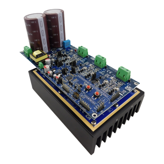
Getting Started with STEVAL-CTM015V1, 1kW, 400Vdc, Three-Phase Switched
Introduction
The
STEVAL-CTM015V1
evaluation kit is designed to provide a complete solution for a three-phase Switched Reluctance Motor
(SRM) drives based on the asymmetric half bridge flexible converter topology.
It is composed by the STEVAL-CTM015A1 drive board, the STEVAL-CTM015A2 power board, and an heatsink already
assembled. Additional information is available in the Ordering information of this document.
The drive board features a DC-DC power supply based on VIPER26, LD1117,
single-chip high and low-side gate drivers for N-channel power MOSFETs or IGBTs.
The power board features an insulated metal substrate (IMS), NTCs for thermal protection, decoupling gate resistors for each
IGBT,
LMV331I
comparators for over current protection,
Turbo 2 Soft Ultrafast Recovery Diode.
The
STEVAL-CTM015V1
features by default the three-shunts resistors current sensing network based on TSV991IL, but the
board supports the Insulated Current Sensors (ICS) for phase currents reading.
UM3174 - Rev 1 - July 2023
For further information contact your local STMicroelectronics sales office.
STGB30H60DFB
Figure 1.
STEVAL-CTM015V1 evaluation kit
Reluctance Motor drive
STM32F303
as MCU,
L6395D
trench gate field-stop together with
UM3174
User manual
high voltage
STTH15RQ06
www.st.com
Advertisement
Table of Contents

Related Manuals for ST STEVAL-CTM015V1

Summary of Contents for ST STEVAL-CTM015V1
-
Page 1: Figure 1. Steval-Ctm015V1 Evaluation Kit
UM3174 User manual Getting Started with STEVAL-CTM015V1, 1kW, 400Vdc, Three-Phase Switched Reluctance Motor drive Introduction STEVAL-CTM015V1 evaluation kit is designed to provide a complete solution for a three-phase Switched Reluctance Motor (SRM) drives based on the asymmetric half bridge flexible converter topology. -
Page 2: Evaluation Kit Features
UM3174 Evaluation kit features Evaluation kit features Electrical and functional characteristics The kit features the following man characteristics: • – Power board with insulated metal substrate (IMS) hosting six STGB30H60DFB IGBTs and six STTH15RQ06 diodes in D PAK-2 package – Three High voltage single-chip high and low-side gate drivers (L6395D) with independent control of high and low-side as required by this application –... -
Page 3: Getting Started
UM3174 Getting started Getting started Safety precautions General terms All operations involving transportation, installation and use, as well as maintenance, has to be carried out by skilled technical personnel (national accident prevention rules must be observed). For the purpose of these basic safety instructions, "skilled technical personnel"... -
Page 4: Intended Use Of Evaluation Kit
UM3174 Intended use of evaluation kit Caution: During assembly, testing, and operation, the evaluation board poses several inherent hazards, including bare wires, moving or rotating parts and hot surfaces. All operations involving transportation, installation, use and maintenance must be performed by skilled technical personnel who is familiar with the installation, use and maintenance of power electronic systems. -
Page 5: Electrical Safety
UM3174 Electrical safety Electrical safety Remove power supply from the evaluation board and electrical loads before performing any electrical measurement. Arrange measurement setup, wiring and configuration paying attention to high voltage sections. Once the setup is complete, power the board. Do not touch the evaluation board when it is powered or immediately after it has been disconnected from the voltage supply as several parts and power terminals containing potentially energized capacitors need time to discharge, and heat-sinks and transformers may still be very hot. -
Page 6: Electromagnetic Compatibility
UM3174 Electromagnetic compatibility 2.11 Electromagnetic compatibility STEVAL-CTM015V1 evaluation kit respects the immunity requirements of the EN 55035, EN 61000-6-1 standards. STEVAL-CTM015V1 evaluation kit can cause radiated emissions beyond limits of the standards EN 55032, EN 61000-6-3 standards. The following figures show the horizontal and vertical antenna polarization. -
Page 7: Figure 3. Antenna Polarization Horizontal Results
UM3174 Electromagnetic compatibility Figure 3. Antenna Polarization Horizontal results Figure 4. Antenna Polarization Vertical results UM3174 - Rev 1 page 7/44... -
Page 8: Evaluation Kit Overview
UM3174 Evaluation kit overview Evaluation kit overview Figure 5. STEVAL-CTM015V1 block diagram Figure 6. Main blocks of the STEVAL$CTM015A1A drive board Gate Drivers L6395D Power Supply Viper26L STM32F303CBT LD1117S50 LD1117S33C Figure 7. Main blocks of STEVAL$CTM015A2B power board Asymmetric H-Bridge... -
Page 9: Dc Input Voltage
UM3174 DC input voltage DC input voltage 3.1.1 Voltage connection The DC Link voltage must be provided through the CN5 screw connector. Caution: Use only insulated laboratory power supply featuring current limitation and protection to power supply the evaluation kit. 3.1.2 Input voltage modes The evaluation kit allows to configure two different modalities regarding the 15 V voltage and subsequent 5 V and... -
Page 10: Dc-Link Voltage Range
UM3174 Motor terminals connection 3.1.5 DC-Link Voltage range • If INT_15V mode is used the tested range voltage is 360 - 420V allowing the right behavior of the flyback converter. • If EXT_15V mode is used the maximum DC Link is 420 V and there is not limitations about its minimum value. -
Page 11: Led Diodes Descriptions
The same connector supports the virtual COM, serial communication between MCU and PC. To do this, the STLINK-V3 device must be connected to the connector CN1 as shown in the figure. (for more details about STLINKV3, please refer to documentation available on www.st.com) Figure 11. -
Page 12: Default Firmware
UM3174 Default firmware Default firmware The evaluation kit is programmed with a default firmware that consists of performing a current control at constant frequency. The firmware has been tested with a three-phase load (RL load) having the following specifics. • R = 10.0 Ω... -
Page 13: Test Reports
UM3174 Test reports Test reports Temperature measurements Figure 13. Temperature measurements at 420W, 400V The temperature measurements of the Power Board have been updated at nominal power during tests in the appliance. Two different NTC sensors have been used: • On-board NTC: B57351V5103J060 (10 kOhm) •... -
Page 14: Table 4. Temperature Measurements At 1000 W Of Power Board Steval-Ctm015A2
UM3174 Temperature measurements Table 4. Temperature measurements at 1000 W of Power board STEVAL-CTM015A2 Supply voltage (V) Ambient temperature during test T (°C) Allowed T (°C) Maximum measured temperature T of part/at: T (°C) Power board - STEVAL-CTM015A2 PWB of power board (T130 °C) Transistor Q2 (T150 °C) Diode D17 (T175 °C) Table 4... -
Page 15: Schematic Diagrams
Schematic diagrams Figure 14. STEVAL-CTM015A1 circuit schematic (1 of 12) J 44 TP 46 TP 47 J umpe r_Fe ma le +15V 5001 5001 SOFT TP 50 SWITCHING HARD 5001 S TTH108A SWITCHING P C13 LS _U BOOT P A8 BAT30KFILM P WM_TIM1_CH1 +15V... -
Page 16: Figure 15. Steval-Ctm015A1 Circuit Schematic (2 Of 12)
Figure 15. STEVAL-CTM015A1 circuit schematic (2 of 12) Motor windings connector DC Bus Voltage Connector STLinkV3 Connector +VDC pha s e _U1 P A13 S WDIO pha s e _U2 Input DC P A14 S WCLK Voltage S P I1_S CK/S WO 360-420V GND_P NRS T... -
Page 17: Figure 16. Steval-Ctm015A1 Circuit Schematic (3 Of 12)
Figure 16. STEVAL-CTM015A1 circuit schematic (3 of 12) Current Sensing ADC input Current Sensing ADC input selection TP 3 curr_U_filt_input 5001 curr_U_Opa mp curr_U_ICS curr_U_filt_input ADC_Curre nt_U J 13 TP 5 5001 J 50 curr_V_filt_input J umpe r_Fe ma le ADC_Curre nt_V TP 7 curr_V_filt_input... -
Page 18: Figure 17. Steval-Ctm015A1 Circuit Schematic (4 Of 12)
Figure 17. STEVAL-CTM015A1 circuit schematic (4 of 12) LS_U, LS_V, LS_W are available as GPIO only if hard switching method is used 2 of 2 1 of 2 P A0 P C13 ADC_Curre nt_U LS _U VSS_1 VDD_1 PC13 P A1 P C14 VDC s e ns e LS _V... -
Page 19: Figure 18. Steval-Ctm015A1 Circuit Schematic (5 Of 12)
Figure 18. STEVAL-CTM015A1 circuit schematic (5 of 12) J 54 DC-DC FLYBACK 400V/15V-7V J um pe r_Fe m a le INT_15V EXT_15V J 17 TP 8 5001 S TP S 2150A Ext15V +15V J 53 EXT_15V +15V_TRAS F +Vbus J um pe r_Fe m a le WE_TRAS F +15V/1A J 16... -
Page 20: Figure 19. Steval-Ctm015A1 Circuit Schematic (6 Of 12)
Figure 19. STEVAL-CTM015A1 circuit schematic (6 of 12) +VDC +Vbus TP 11 5000 S TTH5L06B R142 N.A. S C8 Con1 0.1uF 470uF 500V 470uF 500V Con1 Con1 Con1 Con1 S C1 S C2 S C3 S C4 Con1 Con1 S C5 S C6 Con1 S C7... -
Page 21: Figure 20. Steval-Ctm015A1 Circuit Schematic (7 Of 12)
Figure 20. STEVAL-CTM015A1 circuit schematic (7 of 12) Stator windings Current Sensing - ICS ICS 1 Out_U1 IP + 0.1uF curr_U_ICS IP 1+ VIOUT Open when J MP 1 mounted 0 OHM 20A -5108 IP - BW_S EL 0.0 N.A. IP 1- pha s e _U1 ACS 722LLCTR-20AU-T... -
Page 22: Figure 21. Steval-Ctm015A1 Circuit Schematic (8 Of 12)
Figure 21. STEVAL-CTM015A1 circuit schematic (8 of 12) DC Bus Voltage Sensing Rotor Position/Speed Sensing Default:5V - Closed 2-3 3.3V - Close 1-2 +Vbus Ext. Vcc (max 24V) directly on 2-4 pins J 55 J umpe r_Fe ma le 390K J 39 J 43 J 49... -
Page 23: Figure 22. Steval-Ctm015A1 Circuit Schematic (9 Of 12)
Figure 22. STEVAL-CTM015A1 circuit schematic (9 of 12) Motor Terminal Voltage Sensing VS N1 pha s e _U1 phas e_1 Voltage - INP Volta ge U - INP Voltage - OUT Volta ge U - OUT pha s e _U2 phas e_2 Voltage - INM Volta ge U - INM... -
Page 24: Figure 23. Steval-Ctm015A1 Circuit Schematic (10 Of 12)
Figure 23. STEVAL-CTM015A1 circuit schematic (10 of 12) R146 N.A. TP 30 TP 62 TP 31 5001 100k 5001 R148 5001 R149 R150 pha s e _1 Volta ge - INP 390K 390K 390K N.A. TP 32 5001 100k N.A. 68nF 4.1k 68nF... -
Page 25: Figure 24. Steval-Ctm015A1 Circuit Schematic (11 Of 12)
Figure 24. STEVAL-CTM015A1 circuit schematic (11 of 12) R167 N.A. TP 35 TP 69 TP 36 5001 100k 5001 R169 5001 R170 R171 R100 pha s e _1 Volta ge - INP 390K 390K 390K N.A. TP 39 R103 5001 R102 100k N.A. -
Page 26: Figure 25. Steval-Ctm015A1 Circuit Schematic (12 Of 12)
Figure 25. STEVAL-CTM015A1 circuit schematic (12 of 12) Figure 26. STEVAL-CTM015A2 circuit schematic (1 of 3) S C17 J 28 J 29 S C9 J 27 P WM_VH_P P WM_WH_P S C18 P WM_UH_P Out_V1_P MOUNTED ON P CB IMS Out_W1_P MOUNTED ON P CB IMS Out_U1_P... -
Page 27: Figure 27. Steval-Ctm015A2 Circuit Schematic (2 Of 3)
Figure 27. STEVAL-CTM015A2 circuit schematic (2 of 3) Asymmetric H-Bridge P WM_UH_P P WM_VH_P P WM_WH_P S TTH15RQ06G2 S TTH15RQ06G2 S TGB30H60DFB S TGB30H60DFB S TGB30H60DFB S TTH15RQ06G2 R136 R137 R138 Con1 Out_U1_P Out_V1_P Out_W1_P R134 P WM_UL_P P WM_VL_P P WM_WL_P Con1 Con1... -
Page 28: Bill Of Materials
UM3174 Bill of materials Bill of materials Table 5. STEVAL-CTM015V1 bill of materials Item Q.ty Ref. Part/value Description Manufacturer Order code Table 6. STEV Driver board Not available for separate sale AL-CTM015A1 Table 7. STEV Power board Not available for separate sale... - Page 29 UM3174 Bill of materials Item Q.ty Ref. Part/value Description Manufacturer Order code CAPACITOR 150nF CERAMIC SMD 0603 CAP CER Samsung Electro- 1000PF 25V CL10B102KA8NNNC Mechanics X7R 0603 CAP CER C35 C36 C37 0.1uF 0.1UF 50V AVX Corporation 06035C104KAT2A X7R 0603 Ceramic Multilayer C50 C51 C52...
- Page 30 UM3174 Bill of materials Item Q.ty Ref. Part/value Description Manufacturer Order code CONN CN10 con5-strip-male HEADER .100 STR 5POS DIODE GEN STMicroelectronic D1 D4 D7 STTH108A, SMA PURP 800V STTH108A 1A SMA DIODE D2 D3 D5 D6 BAT30KFILM, SCHOTTKY STMicroelectronic D8 D9 D22 BAT30KFILM SOD-523...
- Page 31 UM3174 Bill of materials Item Q.ty Ref. Part/value Description Manufacturer Order code CONN HEADER con4-2x2-strip- Sullins Connector FEMALE .100 PPTC022LFBN-RC female Solution DUAL STR 4POS CONN HEADER con4-2x2-strip- Sullins Connector J31 J32 FEMALE .100 PPTC022LFBN-RC female Solution DUAL STR 4POS CONN HEADER con6-2x3-strip-...
- Page 32 UM3174 Bill of materials Item Q.ty Ref. Part/value Description Manufacturer Order code RES SMD Panasonic 10K OHM R16 R17 R18 Electronic ERA-3AEB103V 0.1% 1/10W Components 0603 RES SMD R19 R21 R67 10K OHM 1% Yageo RC0603FR-0710KL R69 R70 1/10W 0603 RES SMD 100K OHM 100k...
- Page 33 UM3174 Bill of materials Item Q.ty Ref. Part/value Description Manufacturer Order code CHIP RESISTOR 4.7K Yageo RC0603FR-074K7L SMD 1% 1/10W 0603 R79 R85 R91 CHIP R92 R99 R101 RESISTOR R103 R109 100k SMD 1% R111 R112 1/8W 0805 R114 R115 CHIP R83 R100 RESISTOR...
-
Page 34: Table 7. Steval-Ctm015A2 (Driver Board) Bill Of Materials
UM3174 Bill of materials Item Q.ty Ref. Part/value Description Manufacturer Order code TP1 TP3 TP5 TP7 TP8 TP9 TP10 TP18 TP22 TP26 TP27 TP28 TP29 TP30 TP31 TP32 TP33 TP34 TP35 TP36 TP37 TP38 TEST POINT TP39 TP40 PC MINI Keystone 5001 5001... - Page 35 UM3174 Bill of materials Item Q.ty Ref. Part/Value Description Manufacturer Order code CAPACITOR C38 C39 C42 1 uF CERAMIC WALSIN WAL9064510 C43 C46 C47 SMD 0805 CAPACITOR C40 C44 C48 56nF CERAMIC Kemet C0805C563J5RACTU SMD 0805 CAPACITOR C41 C45 C49 10nF CERAMIC WALSIN...
- Page 36 UM3174 Bill of materials Item Q.ty Ref. Part/Value Description Manufacturer Order code CHIP R47 R48 R55 RESISTOR Royalohm 0805S8F1202T5E R56 R63 R64 SMD 1% 1/8W 0805 CHIP R121 R122 RESISTOR Royalohm 1206S4J0000T5E R123 SMD 1% 1/4W 1206 RES SMD TE Connectivity R134 R135 68K OHM 1% 352168KFT...
-
Page 37: Kit Versions
STEVAL$CTM015A2B 1. This code identifies the STEVAL-CTM015V1 evaluation kit second version. The kit consists of the STEVAL-CTM015A1 driver board, whose version is identified by the code STEVAL$CTM015A1B, the STEVAL-CTM015A2 power board, whose version is identified by the code STEVAL$CTM015A2B, and a 1K/W heat sink already assembled. The STEVAL$CTM015A2B board is mounted in the middle position between the STEVAL$CTM015A1B and the heatsink. -
Page 38: Regulatory Compliance Information
UM3174 Regulatory compliance information Regulatory compliance information Notice for US Federal Communication Commission (FCC) For evaluation only; not FCC approved for resale FCC NOTICE - This kit is designed to allow: (1) Product developers to evaluate electronic components, circuitry, or software associated with the kit to determine whether to incorporate such items in a finished product and (2) Software developers to write software applications for use with the end product. -
Page 39: Revision History
UM3174 Revision history Table 9. Document revision history Date Revision Changes 17-Jul-2023 Initial release. UM3174 - Rev 1 page 39/44... -
Page 40: Table Of Contents
UM3174 Contents Contents Evaluation kit features ............. 2 Getting started . - Page 41 UM3174 Contents List of tables ................42 List of figures.
- Page 42 STEVAL-CTM015V1 bill of materials ........
- Page 43 STEVAL-CTM015V1 block diagram........
- Page 44 ST’s terms and conditions of sale in place at the time of order acknowledgment. Purchasers are solely responsible for the choice, selection, and use of ST products and ST assumes no liability for application assistance or the design of purchasers’...
Need help?
Do you have a question about the STEVAL-CTM015V1 and is the answer not in the manual?
Questions and answers