Sign In
Upload
Manuals
Brands
ST Manuals
Control Unit
AN4070
User Manuals: ST AN4070 Microinverter
Manuals and User Guides for ST AN4070 Microinverter. We have
1
ST AN4070 Microinverter manual available for free PDF download: Application Note
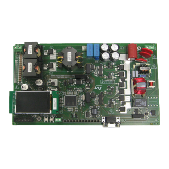
ST AN4070 Application Note (53 pages)
250 W grid connected microinverter
Brand:
ST
| Category:
Control Unit
| Size: 4 MB
Table of Contents
Figure 1. Image of the 250 W MIC
1
Table of Contents
2
1 System Description
5
Figure 2. Block Scheme of the 250 W Grid Connected System
5
2 DC-DC Converter Design
7
Figure 3. DC-DC Converter Topology
7
Figure 4. Gate Driving Signals of the DC-DC Converter
8
Figure 5. Currents through the Input Inductors
8
Figure 6. MOSFET MOS1 and MOS2 Currents
9
Figure 7. Rectifier Diode Currents
9
Figure 8. HF Transformer Current
10
Table 3. DC-DC Converter MOSFET Main Characteristics
13
Table 4. DC-DC Converter Rectifier Diodes Main Characteristics
13
Table 5. HF Transformer Specifications
14
Table 6. RM14 Core with N87 Ferrite Main Characteristics
15
Figure 9. Basic Scheme of the DC-AC Converter
17
Table 7. STB11N65M5 MOSFET Main Electrical Characteristics
19
3 Schematic Description
20
Figure 10. Schematic of the Two Main Power Stages
22
Figure 11. Schematic of the Filtering and Relay Circuit
23
Figure 12. DC-DC Converter Driver
24
Figure 13. DC-AC Converter Driver
25
Figure 14. Auxiliary Power Supply of the Demonstration Board
26
Figure 15. AC Line Current Sensing
26
Figure 16. AC Line Voltage Sensing
27
Figure 17. PV Current Sensing
28
Figure 18. PV Voltage Sensing
28
4 Stm32F103Xx Based Current Control for Inverter Grid Connection
29
Figure 19. Block Diagram of the Implemented Control
29
Figure 20. Implemented PLL Structure
30
Figure 21. Block Diagram of the Control Algorithm Implemented on the 250 W MIC Stm32F103Xx
32
5 Experimental Test Results
35
Figure 23. DC-DC Converter Input Current Ripple Cancellation and Inductor Currents
36
Figure 24. DC-DC Converter HF Transformer Waveforms
36
Figure 25. DC-DC Converter Rectifier Diode Waveforms
37
Figure 26. Inverter Modulating Signals
37
Figure 27. DC-AC Converter Output Voltage and Current Waveforms
38
Figure 28. DC-DC Converter Efficiency
39
Figure 29. Microinverter Efficiency
39
Figure 30. MIC Output Current and Voltage Waveforms During Grid Connection
40
Figure 31. Output Current THD
40
Figure 32. Power Factor
41
Appendix A Magnetic Components Datasheets
42
Figure 33. DC-DC Boost Converter Inductors (Part1)
42
Figure 34. DC-DC Boost Converter Inductors (Part2)
43
Figure 35. AC Voltage TV
44
Figure 36. DC-DC Converter HF Transformer (Part 1)
45
Figure 37. DC-DC Converter HF Transformer (Part 2)
46
Figure 38. Inverter Filter Inductor (Part 1)
47
Figure 39. Inverter Filter Inductor (Part 2)
48
Appendix B Alternative DC-DC Converter Magnetic Components with Low
49
Profile
49
Figure 40. DC/DC Inductor for 250 W Microinverter
49
Figure 41. DC-DC Transformer for 250 W Microinverter
50
6 Conclusions
51
Revision History
52
Document Revision History
52
Advertisement
Advertisement
Related Products
ST A2F12M12W2-F1
ST ACEPACK DRIVE
ST AN4080
ST AN3154
ST AN3155
ST AN3311
ST AN2586
ST AN5717
ST AN3959
ST AN3954
ST Categories
Motherboard
Computer Hardware
Microcontrollers
Control Unit
Controller
More ST Manuals
Login
Sign In
OR
Sign in with Facebook
Sign in with Google
Upload manual
Upload from disk
Upload from URL