Sign In
Upload
Manuals
Brands
SSD Manuals
Inverter
605C
User Manuals: SSD 605C Frequency Inverter
Manuals and User Guides for SSD 605C Frequency Inverter. We have
1
SSD 605C Frequency Inverter manual available for free PDF download: Product Manual
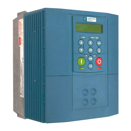
SSD 605C Product Manual (236 pages)
Frequency inverter
Brand:
SSD
| Category:
Inverter
| Size: 4 MB
Table of Contents
Intended Users
3
Table of Contents
5
Etting
13
Optional Equipment
13
S T a R T E D Introduction
13
Equipment Inspection
14
How the Manual Is Organised
14
Application Block Diagrams
15
Quick-Start Guide
15
Information for Users Without an Operator Station
15
Initial Steps
14
About this Manual
14
Nverter
17
Component Identification
17
Control Features
18
Understanding the Product Code
19
Control Board
20
Processor
20
Technology Option Interface
20
Operator Station Interface
20
Functional Overview
20
Power Board
20
Nstalling the
23
Nverter
23
Mechanical Installation
23
Minimum Air Clearances
23
Ventilation
23
Air Clearance: Cubicle-Mount Product/Application
25
Air Clearance: Wall-Mount Product/Application
25
Mounting the Inverter
23
Electrical Installation
26
Wiring the Inverter
26
Protective Earth (PE) Connections
28
Power Wiring Connections
28
Control Wiring Connections
29
Optional Equipment
30
Fitting the Remote 6901 Operator Station
30
Top Cover
31
Technology Options
32
External Brake Resistor
33
External AC Supply EMC Filter
34
Output Contactors
35
Chapter 1 Earth Fault Monitoring Systems
35
Line Chokes (Input)
36
AC Motor Choke (Output)
36
Perating the
37
Nverter
37
Pre-Operation Checks
37
Control Philosophy
38
Start/Stop and Speed Control
38
Selecting Local or Remote Control
39
Remote Control Using Control Terminals (Default Set-Up)
40
Reading the Status Leds
40
Start-Up Routines
40
Local Control Using the Operator Station
41
Quick Set-Up as an Open-Loop Inverter (V/F Fluxing)
41
Setting-Up the Inverter
41
Set-Up Using the Sensorless Vector Fluxing Mode
42
The Autotune Feature
42
Manual Tuning
43
Tuning Using the Motor Equivalent Circuit
43
Tuning Using a Simple Tuning Sequence
43
The Start/Stop Mode Explained
44
Tuning Difficulties
44
Normal Stopping Methods
45
Ramp to Stop
45
Coast to Stop
46
Starting and Stopping Methods
45
Advanced Stopping Methods
46
Forced Fast Stop
46
Forced Coast Stop
47
The Trip Condition
47
Logic Stopping
47
Advanced Starting Methods
48
Starting Several Inverters Simultaneously
48
Single Wire Logic Starting
48
Two Wire Logic Starting
49
Three Wire Logic Starting
49
Normal Starting Method
48
Perator
51
Station
51
Connecting the Operator Station
51
Welcome Screen
51
Customising the Operator Station
51
Controlling the Drive Using the Operator Station
52
Keys for Programming the Drive
52
Keys for Operating the Drive Locally
52
LED Indications
53
Navigating the Menu System
54
The Menu System Map
55
The Menu System
54
Changing a Parameter Value
56
What Do the Symbols Mean Next to some Parameters
56
Parameter Status Information
56
Expanded Menu Information
56
Alert Message Displays
57
The L/R Key
57
The PROG Key
57
The MMI DIAGNOSTICS Menu
58
Menu Shortcuts and Special Key Combinations
60
Quick Link Information
60
Quick Save to Memory
60
Changing the Display Language
60
Quick Drive Copy
60
Changing the Product Code
61
Quick Restore Default
61
Special Menu Features
60
Menu Viewing Levels
61
Startup Screen Timeouts
61
Control Key Enable/Disable
62
Password Protection
62
To Activate Password Protection
62
To Deactivate Password Protection
62
Selecting the Display Language
62
Selecting Parameters for the Operator Menu
63
Selecting a Startup Screen
63
Customising the Welcome Screen
63
Creating Custom Screens
64
Copying an Application
64
Transferring Your Application to Another Inverter
64
Backing-Up Your Application
65
How to Save, Restore and Copy Your Settings
64
Restoring Saved Settings
64
Saving Your Application
64
Chapter 6 PROGRAMMING YOURAPPLICATION
67
Introducing the Macro
67
Programming with Block Diagrams
67
Modifying a Block Diagram
67
Configuration and Parameterisation Modes
67
Making and Breaking Links in Configuration Mode
67
Programming Rules
68
Execution Rules
68
Saving Your Modifications
69
Understanding the Function Block Description
69
MMI Menu Maps
69
Hexadecimal Representation of Trips
70
Function Block Descriptions
71
Analog Digin
72
Analog Input
74
Analog Output
77
Chapter 5 AUTO RESTART
79
Autotune
81
Brake Control
82
Comms Control
83
Current Feedback
84
Current Limit
86
Custom Screen
87
Demultiplexer
89
Digital Input
90
Digital Output
91
Dynamic Braking
92
Encoder
93
Fluxing
94
Flycatching
96
Inj Braking
98
I/O Trips
99
I*T TRIP
100
Chapter 2 JOG
101
Local Control
102
Logic Function
103
Minimum Speed
107
Multiplexer
108
Operator Menu
109
Op Station
110
Password
112
Pattern Gen
113
Chapter 3 PID
114
Preset
116
Chapter 4 RAISE/LOWER
118
Reference
119
Sequencing Logic
121
Setpoint Scale
123
Skip Frequencies
124
Slew Rate Limit
126
Slip Comp
127
Stabilisation
128
Stall Trip
129
Stop
130
System Port (P3)
131
System Ramp
132
Tec Option
134
Trips History
135
Trips Status
136
Underlap Comp
138
Value Function
139
Vector Fluxing
146
Voltage Control
147
Zero Speed
148
Motor-Specific Parameters
149
Quadratic Torque Selection
150
Chapter 7 TRIPS and FAULT FINDING
151
Trips
151
What Happens When a Trip Occurs
151
Inverter Indications
151
Operator Station Indications (When Connected)
151
Resetting a Trip Condition
151
Using the Operator Station to Manage Trips
152
Trip Messages
152
Automatic Trip Reset
153
Setting Trip Conditions
153
Viewing Trip Conditions
153
Checksum Fail
154
Inverter Indications
154
Operator Station Indications (When Connected)
154
Fault Finding
154
Routine Maintenance
155
Chapter 8 ROUTINE MAINTENANCE ANDREPAIR
155
Repair
155
Saving Your Application Data
155
Returning the Unit to SSD Drives
155
Disposal
155
Chapter 10 Principle State Machine
157
Main Sequencing States
157
State Outputs of the SEQUENCING LOGIC Function Block
157
Transition of States
158
State Diagram
159
Chapter 9 SEQUENCING LOGIC
157
External Control of the Inverter
160
Communications Command
160
Example Commands
161
Communications Status
162
Specification
163
Specification Table: Tag Number Order
164
Product-Related Default Values
181
Language Dependant Defaults
181
AC Supply Voltage and Power Rating Dependant Defaults
182
Specifications
185
605C Model Recognition
185
Environmental Details
185
Earthing/Safety Details
186
Terminal Block Wire Sizes
186
Electrical Ratings
187
Cabling Requirements for EMC Compliance
188
EMC Compliance
188
External AC Supply (RFI) Filters
188
Internal Dynamic Brake Switch
189
Control Terminals
190
Analog Inputs/Outputs
191
Digital Inputs
191
Digital Outputs
191
Supply Harmonic Analysis
192
Requirements for EMC Compliance
193
Minimising Radiated Emissions
193
Earthing Requirements
193
Protective Earth (PE) Connections
193
EMC Earth Connections
193
Cabling Requirements
194
Planning Cable Runs
194
Increasing Motor Cable Length
194
EMC Installation Options
195
Screening & Earthing (Wall Mounted, Class A)
195
Screening & Earthing (Cubicle Mounted, Class B)
195
Star Point Earthing
197
Sensitive Equipment
198
Chapter 12 CERTIFICATION for the INVERTER
193
Requirements for UL Compliance
199
Solid-State Motor Overload Protection
199
Short Circuit Rating
199
Solid-State Short-Circuit Protection
199
Recommended Branch Circuit Protection
199
Motor Base Frequency
199
Field Wiring Temperature Rating
199
Field Wiring Terminal Markings
199
Power Wiring Terminals
199
Terminal Tightening Torque
199
Field Grounding Terminals
200
Operating Ambient Temperature
200
Direct Wall-Mountable Models
200
European Directives and the CE Mark
201
CE Marking for Low Voltage Directive
201
CE Marking for EMC - Who Is Responsible
201
Legal Requirements for CE Marking
202
Applying for CE Marking for EMC
202
Which Standards Apply
202
Power Drive Product Specific or Generic Standards
202
Certificates
206
Synchronous Motor Control
207
Chapter 13 APPLICATIONNOTES
207
Brake Motors
207
Using Line Chokes
207
Using Output Contactors
208
Using Motor Chokes
208
Using Multiple Motors on a Single Drive
209
Dynamic Braking
209
Brake Resistor Selection
210
High Starting Torque
211
Chapter 14 SERIAL COMMUNICATIONS
213
Communications Technology Option
213
Configed Lite
213
Connection to the P3 Port
213
Chapter 15 APPLICATIONMACROS
215
The Default Application
215
How to Load a Macro
215
Macro Descriptions
215
Macro 0
215
Macro 1: Basic Speed Control (Default)
217
Macro 2: Run Forward/Run Reverse
219
Macro 3: Raise/Lower Trim
221
Macro 4: Process PID
223
Macro 5: Preset Speeds
225
Macro 6: Closed-Loop Speed Feedback
227
Macro 99: 584S Compatible Application
229
General Wiring Diagram for Macro 99
232
Macro Control Blocks
233
Macro User Blocks
234
Advertisement
Advertisement
Related Products
SSD Categories
Measuring Instruments
Power Supply
Amplifier
Transducer
Inverter
More SSD Manuals
Login
Sign In
OR
Sign in with Facebook
Sign in with Google
Upload manual
Upload from disk
Upload from URL