Table of Contents
Advertisement
Quick Links
605C
Frequency
Inverter
Product Manual
HA465013U001 Issue 8
Compatible with Version 5.x Software
Copyright 2005 SSD Drives Limited (formerly Eurotherm Drives Limited)
All rights strictly reserved. No part of this document may be stored in a retrieval system, or transmitted in any form or by
any means to persons not employed by an SSD Drives company without written permission from SSD Drives Ltd.
Although every effort has been taken to ensure the accuracy of this document it may be necessary, without notice, to
make amendments or correct omissions. SSD Drives cannot accept responsibility for damage, injury, or expenses
resulting therefrom.
Advertisement
Table of Contents

Subscribe to Our Youtube Channel
Summary of Contents for SSD 605C
- Page 1 All rights strictly reserved. No part of this document may be stored in a retrieval system, or transmitted in any form or by any means to persons not employed by an SSD Drives company without written permission from SSD Drives Ltd.
- Page 2 SSD Drives warrants the goods against defects in design, materials and workmanship for the period of 12 months from the date of delivery on the terms detailed in SSD Drives Standard Conditions of Sale IA058393C. SSD Drives reserves the right to change the content and product specification without notice. Cont.2...
-
Page 3: Intended Users
Safety Information Requirements IMPORTANT: Please read this information BEFORE installing the equipment. Intended Users This manual is to be made available to all persons who are required to install, configure or service equipment described herein, or any other associated operation. The information given is intended to highlight safety issues, and to enable the user to obtain maximum benefit from the equipment. - Page 4 The specifications, processes and circuitry described herein are for guidance only and may need to be adapted to the user’s specific application. Refer to page 3-1. SSD Drives does not guarantee the suitability of the equipment described in this Manual for individual applications.
-
Page 5: Table Of Contents
Contents Contents Page Chapter 1 G E T T I N G T A R T E D Introduction ....................1-1 Optional Equipment ....................1-1 Equipment Inspection ................... 1-2 About this Manual ..................1-2 Initial Steps ......................1-2 How the Manual is Organised .................1-2 •... - Page 6 Contents Contents Page • Output Contactors ................3-13 • Earth Fault Monitoring Systems ............3-13 • Line Chokes (input) ................3-14 • AC Motor Choke (output) ..............3-14 Chapter 4 O P E R A T I N G T H E N V E R T E R Pre-Operation Checks ..................
- Page 7 Contents Contents Page Chapter 5 T P E R A T O R T A T I O N Connecting the Operator Station ..............5-1 • Welcome Screen...................5-1 Customising the Operator Station ..............5-1 Controlling the Drive using the Operator Station ........5-2 Control Keys ......................5-2 •...
- Page 8 Contents Contents Page How to Save, Restore and Copy your Settings..........5-14 Saving Your Application ..................5-14 Restoring Saved Settings ..................5-14 Copying an Application ..................5-14 • Transferring Your Application to Another Inverter .........5-14 • Backing-up Your Application ...............5-15 Chapter 6 P R O G R A M M I N G O U R P P L I C A T I O N...
- Page 9 Contents Contents Page • OPERATOR MENU ................6-43 • OP STATION ..................6-44 • PASSWORD..................6-46 • PATTERN GEN..................6-47 • PID ....................6-48 • PRESET ....................6-50 • RAISE/LOWER..................6-52 • REFERENCE ..................6-53 • SEQUENCING LOGIC................6-55 • SETPOINT SCALE................6-57 • SKIP FREQUENCIES ................6-58 • SLEW RATE LIMIT ................6-60 •...
- Page 10 E P A I R Routine Maintenance..................8-1 Repair ......................8-1 Saving Your Application Data ..................8-1 Returning the Unit to SSD Drives ................8-1 Disposal .........................8-1 Chapter 9 S E Q U E N C I N G O G I C Principle State Machine ................
- Page 11 Contents Contents Page Chapter 12 C E R T I F I C A T I O N F O R T H E N V E R T E R Requirements for EMC Compliance ............12-1 Minimising Radiated Emissions ................12-1 Earthing Requirements...................12-1 •...
- Page 12 Contents Contents Page Chapter 13 A P P L I C A T I O N O T E S Synchronous Motor Control ................ 13-1 Brake Motors ....................13-1 Using Line Chokes ..................13-2 Using Output Contactors................13-2 Using Motor Chokes ................... 13-2 Using Multiple Motors on a Single Drive............
-
Page 13: Etting
It is available in a range of ratings for constant torque and quadratic torque applications. This dual mode feature is available on all 605C models and provides a cost effective solution to general industrial applications, as well as the control of pumps and fans. -
Page 14: Equipment Inspection
About this Manual This manual is intended for use by the installer, user and programmer of the 605C Inverter. It assumes a reasonable level of understanding in these three disciplines. Note: Please read all Safety Information before proceeding with the installation and operation of this unit. -
Page 15: Application Block Diagrams
Information for Users without an Operator Station This symbol identifies important text for users operating the 605C Inverter using the default DEFAULT (factory) set-up. If the text is italic, such as this, then the information is especially for users without the Operator Station or suitable PC programming tool. - Page 16 Getting Started 605C Frequency Inverter...
-
Page 17: Nverter
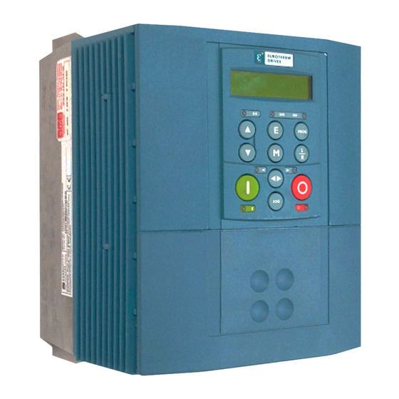
Terminal cover retaining screw Earthing points Terminal cover RS232 programming port Remote operator station port Gland plate Power terminal shield Comms technology option (optional) 6051 operator station (optional) Speed feedback technology option (optional) Blank cover Configuration switches SW1 & SW2 605C Frequency Inverter... -
Page 18: Control Features
An Overview of the Inverter Control Features The 605C Inverter is fully-featured when controlled using the optional Operator Station (or a suitable PC programming tool). The `General’ control features below are not available when the unit is controlled using the DEFAULT analog and digital inputs and outputs. -
Page 19: Understanding The Product Code
An Overview of the Inverter Understanding the Product Code The 605C unit is fully identified using a ten block alphanumeric code which records how the Inverter was calibrated, and its various settings when despatched from the factory. The Product Code appears as the “Model No.”. Each block of the Product Code is identified as below: Note: The Language field controls the default setting for the BASE FREQUENCY parameter. -
Page 20: Functional Overview
Technology Option Interface This is a multi-way connector and processor bus with control signals allowing Speed Feedback and Communications Technology Options to be fitted to the 605C Inverter. Operator Station Interface This is a non-isolated RS232 serial link for communication with the Operator Station. - Page 21 CONNECTOR OPERATOR PROGRAMMING STATION TECHNOLOGY OPTION PORT TECHNOLOGY OPTION INTERFACE INTERFACE INTERFACE CONNECTOR RELAY MOTOR THERMISTOR TERMINALS L2/N Diode Bridge Charging Circuit CONTROL TERMINALS PROCESSOR DBR+ DBR- CONTROL POWER M1 M2 M3 Figure 2-2 Functional Block Diagram 605C Frequency Inverter...
- Page 22 An Overview of the Inverter 605C Frequency Inverter...
-
Page 23: Nstalling The
0110/500 20.5/9.3 All dimensions are in millimetres (inches) Note: Details of a through-panel mounting option for dirty air cooling are available from SSD Drives. Mounting the Inverter The unit must be mounted vertically on a solid, flat, vertical surface. It can be wall-mounted, or mounted inside a suitable cubicle, depending upon the required level of EMC compliance - refer to Chapter 11: “Technical Specifications”... - Page 24 Installing the Inverter equipment may have its own clearance requirements. When mounting two or more 605s together, these clearances are additive. Ensure that the mounting surface is normally cool. 605C Frequency Inverter...
-
Page 25: Air Clearance: Cubicle-Mount Product/Application
1.5Nm (1.2Nm recommended). UL Type 1 Top Cover Heat Control Sink FORCED AIR FLOW Figure 3-3 Air Clearance for a Wall-Mount Product/Application Model Recognition Clearances for Standard Product with UL Type 1 Top Cover (mm) All models 0 (zero) 605C Frequency Inverter... -
Page 26: Electrical Installation
360 degree screened connection to give EMC compliance. A 360 degree screened connection can be achieved as shown. Figure 3-5 360 Degree Screened Connection The receiving hole in the gland plate has a compromised diameter of 28.6mm to accept metric M20, PG16 and American ½” NPT cable gland sizes. 605C Frequency Inverter... - Page 27 2 3 4 5 6 7 8 9 10 11 12 13 14 15 16 17 18 19 20 21 22 23 24 25 26 Power Board MOT/TEMP DBR+ DBR- M1/U M2/V M3/W Figure 3-7 605C Inverter showing Earth, Power and Control Board Terminals 605C Frequency Inverter...
-
Page 28: Protective Earth (Pe) Connections
360 degree to motor screened connection for EMC compliance power wiring International to motor grounding symbol Protective Earth 605C Frequency Inverter... -
Page 29: Control Wiring Connections
11 12 13 14 15 16 17 18 19 20 21 22 23 24 25 26 Speed Setpoint RUNNING HEALTH 220V AC 3A maximum into a resistive load (default) Figure 3-9 Typical Connection to the Control Terminals (as Macro 1) 605C Frequency Inverter... -
Page 30: Optional Equipment
Station into the P3 port (see the diagram on the previous page) ensuring RS232 / REM OP STA that the ferrite is at the drive end of the lead and is as close to the drive as possible. 605C Frequency Inverter... -
Page 31: Top Cover
Figure 3-10 Mounting Dimensions for the Remote-Mounted Keypad 6901 Top Cover This UL Type 1 top cover is fitted to wall-mounted 605C units to give improved compliance ratings. Refer to Chapter 11: “Technical Specifications” - Environmental Details. Align the top cover to be flush with the front of the unit and press the locating pegs firmly into position. -
Page 32: Technology Options
Remove the option by carefully pushing a long screwdriver (for instance) under the option and gently prising it out. The pins are protected by the option moulding. WARNING! Isolate the drive before fitting or removing the option. 605C Frequency Inverter... -
Page 33: External Brake Resistor
Part Number CZ389853 CZ463068 Resistance 100Ω 56Ω Max wattage 100W 200W 5 second rating 500% 500% 3 second rating 833% 833% 1 second rating 2500% 2500% Electrical connection M4 spade M5 spade Table 3-2 Braking Resistor Details 605C Frequency Inverter... -
Page 34: External Ac Supply Emc Filter
Fit a gland box base (A) to the filter at both ends and secure the filter on the wall. Bring the conduit into each end and complete the wiring. Finally, secure the gland box covers (B) using the screws and washers. 605C Frequency Inverter... -
Page 35: Output Contactors
EMC filter’s internal capacitors which are connected between phase and earth. This has been minimised in SSD Drives’ filters, but may still trip out any circuit breaker in the earth system. In addition, high frequency and dc components of earth leakage currents will flow under normal operating conditions. -
Page 36: Line Chokes (Input)
Line chokes may be used to reduce the harmonic content of the supply current where this a particular requirement of the application or where greater protection from mains borne transients is required. Please refer to SSD Drives for the selection of a suitable line choke. AC Motor Choke (output) Maximum Motor dv/dt = 10,000V/µs. -
Page 37: Perating The
Re-apply power to the Inverter and system The Inverter has Macro 1 installed as the factory default. If you are controlling the Inverter in Remote control, refer to Chapter 15: “Application Macros” for details of the most suitable macro for your application. 605C Frequency Inverter... -
Page 38: Control Philosophy
SPEED CONTROL SPEED CONTROL SPEED SETPOINT SPEED SETPOINT DEFAULT LOCAL START/STOP REMOTE START/STOP REMOTE LOCAL SPEED CONTROL SPEED CONTROL SPEED SETPOINT SPEED SETPOINT REMOTE START/STOP LOCAL START/STOP Figure 4-2 The Four Combinations of Local and Remote Control 605C Frequency Inverter... -
Page 39: Selecting Local Or Remote Control
Figure 4-3 Control Mode LED Indications mode is in force. Note: The default is for the L/R key to be operative for both Sequencing and Reference Generation, and to be set for Remote control, i.e. both LEDs will be off. 605C Frequency Inverter... -
Page 40: Start-Up Routines
Re-configuration, or corrupted non-volatile memory at power-up Tripped Auto Restarting Stopped Running with zero reference Running Stopping Braking and running with zero reference Braking and running Braking and stopping Table 4-1 Status indications given by the Health and Run LEDs 605C Frequency Inverter... -
Page 41: Local Control Using The Operator Station
* These values are dependent upon the Language field of the Product Code, e.g. UK ** These values are dependent upon the “power build” of the unit, indicated by the Product Code Table 4-2 Important Parameters for the Open-loop Inverter 605C Frequency Inverter... -
Page 42: Set-Up Using The Sensorless Vector Fluxing Mode
AUTOTUNE ACTIVE complete (after a maximum of 10 seconds), the Inverter is returned to the stopped condition and the AUTOTUNE ENABLE parameter is reset to FALSE. Refer to Chapter 6: “Programming Your Application” - AUTOTUNE for further information. 605C Frequency Inverter... -
Page 43: Manual Tuning
1. Take the manually tuned value for MUTUAL INDUC, and split it into 20% and 80% portions. 2. Enter the 20% portion into LEAKAGE INDUC parameter 3. Enter the 80% portion into MUTUAL INDUC parameter. IMPORTANT: Remember to save the parameter settings. 605C Frequency Inverter... -
Page 44: Tuning Difficulties
When the JOG key is pressed and held, the SPEED DEMAND ramps up to the JOG SETPOINT at a ramp rate set by JOG ACCEL RATE (not shown in the diagram). Release the JOG key to “stop” the Inverter. 605C Frequency Inverter... -
Page 45: Starting And Stopping Methods
SPEED DEMAND REMOTE SETPOINT POWER CIRCUIT SPEED TRIM DISABLED Speed 0% Ramp to zero speed at STOP DELAY RAMP DECEL RATE Ramp SPEED TRIM to zero at STOP RATE Figure 4-7 Ramp to Stop with a Remote Reference 605C Frequency Inverter... -
Page 46: Coast To Stop
/FAST STOP input goes FALSE, regardless of the state of the RUN input. /FAST STOP SPEED DEMAND REMOTE SETPOINT POWER SPEED TRIM CIRCUIT DISABLED Speed 0% Ramp SPEED DEMAND to zero at FAST STOP RATE FAST STOP LIMIT Figure 4-10 Forced Fast Stop RAMP Mode example 605C Frequency Inverter... -
Page 47: Forced Coast Stop
JOG ignored as JOG immediately effective complete before acting on already running as previous mode was JOG RUN FWD /STOP REMOTE SETPOINT JOG SETPOINT Speed 0% SPEED DEMAND Figure 4-13 Example of the Interaction between RUN and JOG Parameters 605C Frequency Inverter... -
Page 48: Normal Starting Method
Sequencing Logic RUN FWD RUN REV FALSE REMOTE REVERSE FALSE FALSE /STOP FALSE /FAST STOP TRUE /COAST STOP TRUE DRIVE ENABLE TRUE Figure 4-15 Single Wire Sequencing example 605C Frequency Inverter... -
Page 49: Two Wire Logic Starting
Normally open push button switch Sequencing Logic RUN FWD RUN REV FALSE REMOTE REVERSE FALSE /STOP TRUE /FAST STOP Normally closed TRUE /COAST STOP push button switch TRUE DRIVE ENABLE Figure 4-17 Push Button Bi-directional Sequencing example 605C Frequency Inverter... - Page 50 4-14 Operating the Inverter 605C Frequency Inverter...
-
Page 51: Perator
HINT: Customise the action of the Operator Station to create an effective working tool. Spend time setting up the OPERATOR menu, as this is the list of parameters most used in the operation of your Inverter. Refer to “Special Menu Features”, page 5-8. 605C Frequency Inverter... -
Page 52: Controlling The Drive Using The Operator Station
Local Start/Stop (Seq) mode. STOP/RESET Control - Stops the motor. Only operates when the drive is in Local Sequence mode. Trip Reset - Resets any trips and clears displayed message if trip is no longer active. 605C Frequency Inverter... -
Page 53: Led Indications
FWD/REV keys. Speed Control (Ref) is controlled from the terminals Start/Stop (Seq) is controlled from the terminals Speed Control (Ref) is controlled using the up (∆) and down (∇) keys Start/Stop (Seq) and Speed Control (Ref) are controlled using the Operator Station keys 605C Frequency Inverter... -
Page 54: The Menu System
Refer to “The Menu System Map” to see how the NAVIGATING THE MENU menu is mapped. HINT: Remember that because the Menu and Parameter lists are looped, the ∆ key can quickly move you to the last Menu or Parameter in the loop. 605C Frequency Inverter... -
Page 55: The Menu System Map
ADVANCED VIEW ONLY OPERATOR MENU CUSTOM SCREEN 1 CUSTOM SCREEN 2 SERIAL LINKS COMMS CONTROL SYSTEM PORT (P3) TEC OPTION VALUE FUNCTION VALUE FUNC 1 MISCELLANEOUS VALUE FUNC 10 LOGIC FUNCTION LOGIC FUNC 1 LOGIC FUNC 10 MULTIPLEXER DEMULTIPLEXER 605C Frequency Inverter... -
Page 56: Changing A Parameter Value
AR TRIGGERS 1, AR TRIGGERS+ 1, AR TRIGGERS 2 AR TRIGGERS+ 2 TRIPS STATUS menu at level 4: DISABLED TRIPS, DISABLED TRIPS+, ACTIVE TRIPS, ACTIVE TRIPS+, TRIP WARNINGS, TRIP WARNINGS+ OP STATION menu at level 4: ENABLED KEYS 605C Frequency Inverter... -
Page 57: Alert Message Displays
• COMMS SETPOINT is displayed as SETPOINT (COMMS) Pressing the L/R key when in Remote mode takes you directly to the SETPOINT (LOCAL) parameter with the Edit mode enabled. Press the PROG key to return to the previous display. 605C Frequency Inverter... -
Page 58: The Mmi Diagnostics Menu
0000 to FFFF Indictes which trips are currently active. (Refer to the TRIPS STATUS function block) ACTIVE TRIPS+ Tag No. 740 0000 to FFFF Indictes which trips are currently active. (Refer to the TRIPS STATUS function block) 605C Frequency Inverter... - Page 59 FALSE / TRUE The True or False output demand. (Refer to the DIGITAL OUTPUT function block DOUT 3 VALUE Tag No. 737 FALSE / TRUE The True or False output demand. (Refer to the DIGITAL OUTPUT function block 605C Frequency Inverter...
-
Page 60: Special Menu Features
Operator Station to the Inverter. The Operator Station will still contain the application data, allowing transfer to successive units. This information is replaced by any subsequent SAVE TO OP operation. 605C Frequency Inverter... -
Page 61: Changing The Product Code
The Startup screen will be displayed after an extended period without a key press when viewing the Welcome screen or the VIEW LEVEL parameter in the MENUS menu at level 1. Basic viewing level There is no timeout Advanced viewing level There is no timeout 605C Frequency Inverter... -
Page 62: Selecting The Display Language
Note: You can also choose to have the password protect 0000 the entire OPERATOR menu, or just the SETPOINT (LOCAL) parameter. Under default conditions these HEALTH LOCAL are not protected. Refer to Chapter 6: “Programming Your Application” - PASSWORD. 605C Frequency Inverter... -
Page 63: Selecting Parameters For The Operator Menu
2. Use the up (∆) and down (∇) keys to scroll through the character set for each of the 16 character spaces. Press the M key to move to the next character. Press the E key to exit the parameter. 605C Frequency Inverter... -
Page 64: Creating Custom Screens
2. Two sub-menus allow you to choose between loading a full parameter load which includes motor-specific data, or just the application without any motor-specific data: ALL PARAMETERS APPLICATION ONLY Refer to Chapter 6: “Programming Your Application” - Motor-Specific Parameters. 605C Frequency Inverter... -
Page 65: Backing-Up Your Application
Refer to “Transferring Your Application to Another Inverter” above. You can have the Operator Station back-up the application each time a SAVE TO MEMORY is performed by enabling the AUTO BACKUP parameter. Refer to Chapter 6: “Programming Your Application” - OP STATION. 605C Frequency Inverter... - Page 66 5-16 The Operator Station 605C Frequency Inverter...
-
Page 67: Introducing The Macro
There are 50 links available, each has its own identification number (“link” number). You make a link by setting the link’s “source” and “destination” tags to be the two parameter tag numbers to be linked. The outputs of function blocks are not updated whilst in this mode. 605C Frequency Inverter... -
Page 68: Programming Rules
FALSE Boolean XXX.XX 0.00 0.01 XXX.XX Boolean TRUE 0.00 XXX.XX Boolean FALSE LOCAL ONLY (1) Enumerated XXX.XX 0.01 0.02 XXX.XX Enumerated REMOTE ONLY (2) Note that (2) will not always return Remote Only Table 6-1 Execution Rules 605C Frequency Inverter... -
Page 69: Saving Your Modifications
Because of this intuitive naming of parameters, which is designed to make using the Operator AIN 2 OFFSET Station easier, MMI parameter names may vary slightly from Function Block names. AIN 2 TYPE AIN 2 BREAK ENBL AIN 2 BREAK VAL AIN 2 VALUE AIN 2 BREAK 605C Frequency Inverter... -
Page 70: Hexadecimal Representation Of Trips
“1” in digit 3, an “8” and a “2” in digit 2, (8+2 = 10, displayed as A), and an “8” in digit 1. This in turn represents the active trips I*T TRIP, MOTOR STALLED, INPUT 1 BREAK and HEATSINK TEMP, (an unlikely situation). 605C Frequency Inverter... -
Page 71: Function Block Descriptions
6-68 I*t TRIP 6-34 TRIPS HISTORY 6-69 6-35 TRIPS STATUS 6-70 LOCAL CONTROL 6-36 UNDERLAP COMP 6-72 LOGIC FUNCTION 6-37 VALUE FUNCTION 6-73 MINIMUM SPEED 6-41 VECTOR FLUXING 6-80 MULTIPLEXER 6-42 VOLTAGE CONTROL 6-81 ZERO SPEED 6-82 605C Frequency Inverter... -
Page 72: Analog Digin
LEVEL will cause the output VALUE to be TRUE. Similarly, an input less than the comparison LEVEL will cause the output VALUE to be FALSE. +10V 100% raw input LEVEL -10V TRUE 1 (TRUE) VALUE FALSE 0 (FALSE) 605C Frequency Inverter... - Page 73 The hardware range is selected using switch bank SW1 on the control PCB, as described under the ANALOG INPUT function block. Nominal Hardware Range Hardware Input Equivalent % Suggested Level 0 to 20mA 20mA -10 to 10V -10V 100% 0 to 10V 100% 605C Frequency Inverter...
-
Page 74: Analog Input
Enumerated Value : Type 0 : 0..+10 V 1 : +2..+10 V 2 : 0..+5 V 3 : +1..+5 V 4 : -10..+10 V 5 : 0..20 mA 6 : 4..20 mA 7 : 20..4 mA 8 : 20..0 mA 605C Frequency Inverter... - Page 75 0.1V or 0.45mA. When an input break has been detected, the VALUE output is forced to be the BREAK VALUE . TYPE SCALING OFFSET UNPROCESSED INPUT BREAK VALUE VALUE BREAK INPUT LOSS LEVEL BREAK ENABLE 605C Frequency Inverter...
- Page 76 SW1/3 OFF, SW1/4 ON INPUT Terminal 2 0-10V* SW1/3 OFF, SW1/4 OFF* ± 10V SW1/3 ON, SW1/4 OFF * Default settings, as shown Figure 6-3 I/O Configuration Switches shown at Manufacturing Defaults Table 6-2 Select Input Signal 605C Frequency Inverter...
-
Page 77: Analog Output
If ABS is TRUE then the final output is the magnitude of value after being scaled and offset. If ABS is FALSE then the final output will be limited to be within the range selected by TYPE. 605C Frequency Inverter... - Page 78 Switch Settings ANALOG 0-20 or 4-20mA SW2/1 OFF, SW2/2 OFF OUTPUT Terminal 6 0-10V* SW2/1 ON, SW2/2 ON* * Default settings, as shown Table 6-3 Select Input Signal Figure 6-4 I/O Configuration Switches shown at Manufacturing defaults 605C Frequency Inverter...
-
Page 79: Auto Restart
If a trip is included in both TRIGGERS 1 and TRIGGERS 2, then the times associated with TRIGGERS 1 will take priority. Refer to “Hexadecimal Representation of Trips” at the beginning of this chapter for an explanation of the four-digit codes. 605C Frequency Inverter... - Page 80 Indicates the number of attempts left before an external fault reset is required. TIME LEFT Range: xxxx.x s When in the timing sub-state, this parameter indicates the time left before an auto restart attempt will be permitted. When non-zero, this value is unaffected by changes to ATTEMPT DELAY 1. 605C Frequency Inverter...
-
Page 81: Autotune
Autotune can only be initiated from the “stopped” condition. The function block cannot be changed whilst the drive is running. When the test is complete, the stack is disabled and the motor left to coast. 605C Frequency Inverter... -
Page 82: Brake Control
TRUE for the duration set by OFF HOLD TIME or ON HOLD TIME. Functional Description frequency ON FREQUENCY OFF FREQUENCY time load ON LOAD time RELEASE time HOLD time t = ON HOLD TIME t = OFF HOLD TIME 605C Frequency Inverter... -
Page 83: Comms Control
Diagnostic indicating if operating in Remote Sequencing Comms Mode COMMS REF Range: FALSE / TRUE Diagnostic indicating if operating in Remote Reference Comms Mode. If FALSE (0), the Inverter may be in Local Reference mode or Remote Reference Terminal mode. 605C Frequency Inverter... -
Page 84: Current Feedback
Inverter and is seen as a % of the FULL LOAD CALIB setting. I MAGNETISING Range: xxxx.x A This diagnostic contains the level of magnetising (flux producing) rms line current component being drawn from the Inverter. 605C Frequency Inverter... - Page 85 100.0% in the field diagnostic indicates that the motor is operating at rated flux. The torque current component is re-scaled to provide a LOAD diagnostic. A value of 100.0% in the load diagnostic indicates that the motor is operating at rated torque or full load. 605C Frequency Inverter...
-
Page 86: Current Limit
1 : LOAD REGEN LIM ENABLE Range: FALSE / TRUE This parameter enables or disables REGEN I LIMIT. LIMITING Range: FALSE / TRUE This diagnostic indicates whether the current limit is active (altering Inverter output frequency) or inactive. 605C Frequency Inverter... -
Page 87: Custom Screen
8 : X.XXX_ FORMULA Range: Enumerated - see below Enumerated Value : Formula 0 : A/B * X + C 1 : A/B * (X+C) 2 : A/(B * X) + C 3 : A/(B * (X+C)) 605C Frequency Inverter... - Page 88 Refer to the OPERATOR MENU function block description for details of how to display the custom screens on the Operator menu. Character Sets The table below lists the characters supported by the software in decimal and hexadecimal. ’ “ & ‘ < > 605C Frequency Inverter...
-
Page 89: Demultiplexer
Parameter Descriptions INPUT Range: 0000 to FFFF The input to be split into its component bits. OUTPUT 0 TO OUTPUT 15 Range: FALSE / TRUE Each output returns the corresponding bit of the 16 bit input word. 605C Frequency Inverter... -
Page 90: Digital Input
The input electronics of the Inverter converts the input signal to a TRUE or FALSE logic value. The digital input block takes this value and optionally inverts it before providing the VALUE output. INVERT UNPROCESSED VALUE INPUT 605C Frequency Inverter... -
Page 91: Digital Output
DIGITAL OUTPUT 1 is associated with terminals 21 & 22 DIGITAL OUTPUT 2 is associated with terminals 23 & 24 DIGITAL OUTPUT 3 is associated with terminals 25 & 26 INVERT reverses the output logic. INVERT OUTPUT VALUE 605C Frequency Inverter... -
Page 92: Dynamic Braking
With this information the Inverter is able to deduce the loading on the brake resistor. An optional trip may be enabled should the resistor be loaded beyond its capabilities. Refer also to Chapter 13: “Application Notes” - Dynamic Braking. 605C Frequency Inverter... -
Page 93: Encoder
POSITION Range: xxxxx Number of encoder “counts” from when RESET was set to FALSE. The value will increment or decrement depending on the direction the encoder is rotated. The value will “wrap around” between 32767 and -32768. 605C Frequency Inverter... -
Page 94: Fluxing
Setting the value of auto boost too high can cause the Inverter to enter current limit. If this occurs, the Inverter will be unable to ramp up in speed. Reducing the value of auto boost will eliminate this problem. 605C Frequency Inverter... - Page 95 Correct no-load motor fluxing at low Inverter output frequencies can be achieved by setting the FIXED BOOST parameter. Correct motor fluxing under load conditions is achieved by setting the AUTO BOOST parameter. The motor is correctly fluxed when the FIELD diagnostic in the CURRENT FEEDBACK function block reads 100.0% . 605C Frequency Inverter...
-
Page 96: Flycatching
The rate of rise of volts from the search level to the working level after a successful speed search. Refluxing the motor too quickly can cause the drive to trip on either overvoltage or overcurrent. In either case, increasing this parameter will reduce the risk of tripping. 605C Frequency Inverter... - Page 97 Initially, the search is performed in the direction of the speed setpoint. If the drive fails to identify the motor speed in this direction, a second speed search is performed in the reverse direction. Unidirectional The search is performed only in the direction of the speed setpoint. 605C Frequency Inverter...
-
Page 98: Inj Braking
BASE VOLTS Range: 0.00 to 115.47 % Determines the maximum volts at base speed applied to the motor during injection braking. ACTIVE Range: FALSE / TRUE Indicates the state of the Inverter. TRUE when injection braking. 605C Frequency Inverter... -
Page 99: I/O Trips
Functional Description The I/O TRIPS function block allows trips to be generated by signals on the input terminals of the Inverter. Refer to Chapter 7 for a description of the trips supported by the Inverter. 605C Frequency Inverter... -
Page 100: I*T Trip
This avoids spurious trips while maintaining the monitoring function. Refer to Chapter 7 for a description of the trips supported by the Inverter. 605C Frequency Inverter... -
Page 101: Jog
The JOG function block is used to configure the action of the Inverter when used in jog mode. The various operating modes are described in more detail in Chapter 4: “Operating the Inverter” - The Start/Stop Mode Explained. 605C Frequency Inverter... -
Page 102: Local Control
When FALSE, direction is a Reference command. REMOTE SEQ Range: FALSE / TRUE This parameter indicates the present source of the sequencing commands. REMOTE REF Range: FALSE / TRUE This parameter indicates the present source of the reference signal. 605C Frequency Inverter... -
Page 103: Logic Function
NOT(A) – [229] TYPE – Parameter Descriptions INPUT A Range: FALSE / TRUE General purpose logic input. INPUT B Range: FALSE / TRUE General purpose logic input. INPUT C Range: FALSE / TRUE General purpose logic input. 605C Frequency Inverter... - Page 104 TRUE. OUTPUT INPUT B INPUT C OR(A,B,C) If at least one of A or B or C is OR(A,B,C) TRUE then the OUTPUT is INPUT A TRUE, otherwise the OUTPUT is FALSE. INPUT B OUTPUT INPUT C 605C Frequency Inverter...
- Page 105 C TRUE Duration 20ms Falling Edge Trigger Input B is not used. This function outputs a pulse of 20ms duration when INPUT A to the block becomes FALSE. When INPUT C is TRUE, the output is inverted. 605C Frequency Inverter...
- Page 106 INPUT A OUTPUT INPUT B as reset . INPUT B R FLIP-FLOP This is a reset dominant flip- R FLIP-FLOP flop. INPUT A functions as INPUT A reset, and INPUT B as set . OUTPUT INPUT B 605C Frequency Inverter...
-
Page 107: Minimum Speed
= 300.00% – (2 x min) the input such that the output goes linearly between minimum and 100% for an input that goes from 0 to 100%. Note the constraints:- min >= 0 input >= 0 input max = 100% 100% 200% 605C Frequency Inverter... -
Page 108: Multiplexer
INPUT 12 INPUT 13 INPUT 14 INPUT 15 Parameter Descriptions OUTPUT INPUT 0 TO INPUT 15 Range: FALSE / TRUE The Boolean inputs to be assembled into a single word. OUTPUT Range: 0000 to FFFF The resulting word. 605C Frequency Inverter... -
Page 109: Operator Menu
255: SPEED DEMAND 591: DRIVE FREQUENCY 67: MOTOR CURRENT 72: LOAD 75: DC LINK VOLTS 370: CURRENT LIMITING Also, the Startup screen is selected to display OPERATOR MENU 1, which is fixed to display the SETPOINT parameter. 605C Frequency Inverter... -
Page 110: Op Station
ENABLED ENABLED 0060 ENABLED ENABLED 0070 ENABLED ENABLED ENABLED 0080 ENABLED 0090 ENABLED ENABLED 00A0 ENABLED ENABLED 00B0 ENABLED ENABLED ENABLED 00C0 ENABLED ENABLED 00D0 ENABLED ENABLED ENABLED 00E0 ENABLED ENABLED ENABLED 00F0 ENABLED ENABLED ENABLED ENABLED 605C Frequency Inverter... - Page 111 When TRUE, this diagnostic output indicates that the connected Operator Station contains a configuration that may be loaded into the Inverter. OP VERSION Range: 0000 to FFFF Displays the software version of the Operator Station. It is cleared to 0000 if no Operator Station is connected. 605C Frequency Inverter...
-
Page 112: Password
Enables password protection of all parameters shown in the OPERATOR menu (except for the local setpoint entry). When set to TRUE, the parameters are read-only whenever the inverter is password locked. When FALSE, the parameters can be adjusted regardless of the password. 605C Frequency Inverter... -
Page 113: Pattern Gen
(e.g. 9kHz) reduces audible motor noise but only at the expense of higher Inverter losses and smooth motor rotation at low output frequencies. A low setting of carrier frequency (e.g. 3kHz), reduces Inverter losses but increases audible motor noise. 605C Frequency Inverter... -
Page 114: Pid
This parameter is the true proportional gain of the PID controller. With a P gain of zero, the PID output would be zero. I TIME CONST Range: 0.01 to 100.00 s The integral time constant of the PID controller. 605C Frequency Inverter... - Page 115 This error term is then used by the PID. The output of the PID may be used to trim the demand setpoint via the SPEED TRIM parameter in the REFERENCE function block. 605C Frequency Inverter...
-
Page 116: Preset
0.00 % – [559] INPUT 5 – 0.00 % – [548] INPUT 5 – 0.00 % – [560] INPUT 6 – 0.00 % – [549] INPUT 6 – 0.00 % – [561] INPUT 7 – 0.00 % – [550] INPUT 7 – 605C Frequency Inverter... - Page 117 When SELECT INPUT is set to 4, 5, 6 or 7, OUTPUT 2 will return a value of zero. SELECT INPUT INPUT 0 INPUT 1 INPUT 2 INPUT 3 OUTPUT 1 INPUT 4 INPUT 5 INPUT 6 INPUT 7 OUTPUT 2 605C Frequency Inverter...
-
Page 118: Raise/Lower
RAMP RATE. If OUTPUT is less than MIN VALUE the OUTPUT will ramp up to MIN VALUE at RAMP RATE. IMPORTANT: Do not set MIN VALUE to greater than MAX VALUE, as the resulting value of OUTPUT will be unpredictable. 605C Frequency Inverter... -
Page 119: Reference
Indicates demanded direction. This may not be the actual direction as no account of setpoint sign is taken. LOCAL SETPOINT Range: 0.00 to 100.00 % Indicates the Operator Station setpoint. It is always a positive quantity; saved on power down. Direction is taken from LOCAL REVERSE. 605C Frequency Inverter... - Page 120 (Mode is selectable in COMMS CONTROL block) Local Reference SPEED SETPOINT MAX SPEED CLAMP sign change SYSTEM SPEED DEMAND LOCAL SETPOINT * RAMP SPEED TRIM TRIM IN LOCAL MIN SPEED CLAMP REVERSE LOCAL REVERSE * Set only from the Operator Station 605C Frequency Inverter...
-
Page 121: Sequencing Logic
Setting this parameter to FALSE disables the Inverter operation and causes the motor to coast. The action of setting this parameter to TRUE is latched. The Inverter can not be restarted until the coast stop is completed. 605C Frequency Inverter... - Page 122 This parameter indicates the current state of remote direction and RUN REV. Note - this is the demanded direction, not the actual direction. HEALTHY Range: FALSE / TRUE Set FALSE when the Inverter trips, and set TRUE when the run command is removed. 605C Frequency Inverter...
-
Page 123: Setpoint Scale
The function blocks on the output side of this block process the setpoint as a percentage of the LIMIT FREQUENCY. MAX SPEED LIMIT FREQUENCY ÷ OUTPUT INPUT 605C Frequency Inverter... -
Page 124: Skip Frequencies
Diagnostic on the output of the function block in % OUTPUT HZ Range: xxxx.x Hz Diagnostic on the output of the function block in Hz INPUT HZ Range: xxxx.x Hz Diagnostic on the input of the function block in Hz 605C Frequency Inverter... - Page 125 Setting the BAND to 0 causes the value of BAND 1 to be used for this band. The behaviour of this function block is illustrated below. Drive Frequency Skip band Skip Frequency Setpoint Drive Frequency Frequency 2 Frequency 1 Setpoint Drive Frequency Frequency 1 Frequency 2 Setpoint 605C Frequency Inverter...
-
Page 126: Slew Rate Limit
This causes the slew rate limits block to hold the setpoint at its current value. This typically lasts for only 1ms, time for the excess energy to be dumped into the braking resistor. HOLD SIGNAL ACCEL LIMIT SETPOINT DECEL LIMIT 605C Frequency Inverter... -
Page 127: Slip Comp
Based on the rated speed, the no load speed and the rated load of the motor, the slip compensation block adjusts the demand frequency to compensate for any speed slippage resulting from the load. Torque No Load Speed (synchronous speed) Rated Torque Speed Rated Speed 605C Frequency Inverter... -
Page 128: Stabilisation
This can be experienced at approximately half full speed, and under 2 FUNCTION BLOCKS low load conditions. 3 MOTOR CONTROL 4 STABILISATION STB ENABLE Parameter Descriptions ENABLE Range: FALSE / TRUE Enables (or disables) the stabilisation function. 605C Frequency Inverter... -
Page 129: Stall Trip
If the estimated load exceeds the STALL LIMIT for a time greater than STALL TIME then the stall trip will become active. The timer is reset whenever the estimated load is less than the STALL LIMIT. Refer to Chapter 7 for a description of the trips supported by the Inverter. 605C Frequency Inverter... -
Page 130: Stop
Rate at which the SPEED DEMAND is ramped to zero (see REFERENCE function block) FINAL STOP RATE Range: 12 to 4800 Hz/s Rate at which any internally generated setpoint trims are removed. For example, the trim due to the slip compensation block. 605C Frequency Inverter... -
Page 131: System Port (P3)
The parameters below are used to identify 3 SERIAL LINKS the Inverter to the controlling software. 4 SYSTEM PORT (P3) The port uses the SSD Drives standard EI BISYNCH ASCII protocol. GROUP ID (GID) UNIT ID (UID) Parameter Descriptions GROUP ID (GID) Range: 0 to 9 The SSD Drives protocol group identity address. -
Page 132: System Ramp
Sets the acceleration rate in units of percent per second², i.e. if the full speed of the machine is 1.25m/s then the acceleration will be: 1.25 x 75.00% = 0.9375m/s² SRAMP DECEL Range: 0.00 to 100.00 % This functions in the same way as SRAMP ACCEL above. 605C Frequency Inverter... - Page 133 Chapter 4: “Operating the Inverter” - Starting and Stopping Methods, describes the use of the system ramp. The ramp output takes the form shown below. S-Ramp Acceleration Deceleration Jerk 1 Jerk 4 Jerk 2 Jerk 3 Time (secs) Jerk Acceleration Velocity 605C Frequency Inverter...
-
Page 134: Tec Option
The version of the Technology Option. If no option is fitted then the version is reset to zero. OUTPUT 1 and OUTPUT 2 Range: 0000 to FFFF The use of these output parameters depends on the type of Technology Option fitted. Refer to the Technology Option Technical Manual. 605C Frequency Inverter... -
Page 135: Trips History
Every time a new trip occurs this is entered as TRIP 1 (NEWEST and the other recorded trips are moved down. If more than ten trips have occurred since the Inverter was configured then only the ten most recent trips will be available for inspection. These parameters are preserved through a power failure. 605C Frequency Inverter... -
Page 136: Trips Status
12 : OP STATION 13 : LOST COMMS 14 : 15 : 16 : 17 : MOTOR TEMP 18 : CURRENT LIMIT 19 : SHORT CIRCUIT 20 : 24V FAILURE 21 : LOW SPEED I 22 : PHASE FAIL 605C Frequency Inverter... - Page 137 The ACTIVE TRIPS, WARNINGS and DISABLED TRIPS parameters use a four digit hexadecimal number to identify individual trips. Each trip has a unique corresponding number. Refer to “Hexadecimal Representation of Trips” at the beginning of this Chapter. 605C Frequency Inverter...
-
Page 138: Underlap Comp
The delay causes errors in the Inverter output voltage leading to non- sinusoidal motor currents at low motor speeds. The result is motor cogging, and a loss of motor torque at low speeds. Underlap compensation removes underlap errors, and provides consistent motor operation regardless of motor speed. 605C Frequency Inverter... -
Page 139: Value Function
If inputs and outputs are time values, divide the time in seconds by a factor of ten, i.e. 11.3 seconds = 1.13%. Conversely, outputs are multiplied by a factor of ten to obtain their value in seconds. Boolean inputs or outputs are FALSE if zero, and TRUE if non-zero. 605C Frequency Inverter... - Page 140 OUTPUT is set to INPUT A, INPUT B otherwise the output is set to INPUT C INPUT B (A*B)/C The OUTPUT is set to (INPUT A * INPUT B) / (INPUT C). The algorithm compensates for the remainder term. 605C Frequency Inverter...
- Page 141 INPUT B INPUT A OUTPUT 0.00 ≠0 0.01 ≠0 0.02 ≠0 ≠0 0.03 ≠0 0.04 ≠0 ≠0 0.05 ≠0 ≠0 0.06 ≠0 ≠0 ≠0 0.07 In the above table, ≠0 indicates that the corresponding input is not zero. 605C Frequency Inverter...
- Page 142 INPUT A becoming FALSE starts the delay timer. INPUT B sets the duration of the delay. Setting INPUT C to TRUE (≠0) inverts the output. At the end of the duration, OUTPUT becomes FALSE unless INPUT A has reverted to TRUE. 605C Frequency Inverter...
- Page 143 TRUE. (INPUT A is assumed to be a sequence of TRUE pulses and FALSE off periods.) INPUT B sets the length of the minimum pulse required. INPUT C inverts the output when TRUE. The duration of the pulse is at least the period set by INPUT B. 605C Frequency Inverter...
- Page 144 INPUT B (this is fulfilled in the default condition when inputs A, B & C are all zero) If INPUT C is set to a negative value, its absolute value defines the window range, and the output is inverted. 605C Frequency Inverter...
- Page 145 This is the same as WINDOW (enumerated value 19) except that there is no NO HYST hysterisis when inside the `window’. Thus, from the diagram given in WINDOW, if INPUT B = 5 and INPUT C = 4 then the range is 3 to 7. 605C Frequency Inverter...
-
Page 146: Vector Fluxing
Range: 0.0 to 1000.0 mH This parameter is used to program the value of the motor per-phase stator mutual (magnetising) inductance. SUPPLY VOLTAGE Range: xxxx.x V This parameter indicates the line to line rms supply voltage to the Inverter. 605C Frequency Inverter... -
Page 147: Voltage Control
VOLTAGE MODE parameter above when set to FIXED. BASE VOLTS Range: 0.00 to 115.47 % This parameter directly scales the output of the voltage control function block, thus allowing further scaling of the Inverter output volts if required. 605C Frequency Inverter... -
Page 148: Zero Speed
AT ZERO SPEED Range: FALSE / TRUE TRUE when at zero, as defined by the LEVEL and BAND parameters. Functional Description Example where BAND = 0.2% input 0.7% BAND window (LEVEL) 0.5% 0.3% true zero AT ZERO SPEED 605C Frequency Inverter... -
Page 149: Motor-Specific Parameters
LEAKAGE INDUC MUTUAL INDUC MOTOR VOLTS VECTOR FILTER TC MOTOR CONNECTION POWER FACTOR ENCODER LINES FLY SEARCH VOLTS FLY SEARCH TIME INJ FREQUENCY INJ DC PULSE INJ FINAL DC INJ DC LEVEL DEFLUX TIME INJ BASE VOLTS 605C Frequency Inverter... -
Page 150: Quadratic Torque Selection
CURRENT FEEDBACK NO LOAD CALIB Default NO Refer to Chapter 10: LOAD CALIB “Parameter Specification”, Amps Power Rating Dependant Defaults CURRENT LIMIT MOTOR LIMIT 150.00% High limit now 150.00% CURRENT LIMIT REGEN I LIMIT -150.00% Low limit now -150.00% 605C Frequency Inverter... -
Page 151: Trips
Reset the trip(s) using the remote trip reset input, or by pressing the STOP/RESET key on the DEFAULT Operator Station. Success is indicated by the HEALTH LED (on the unit or MMI) ceasing to flash and returning to a healthy “ON” state. The programming block SEQUENCING LOGIC::TRIPPED output is reset to FALSE. 605C Frequency Inverter... -
Page 152: Using The Operator Station To Manage Trips
External dynamic braking resistor has Trying to decelerate a large inertia load too quickly or been overloaded too often BRAKE SWITCH Internal dynamic braking switch has Trying to decelerate a large inertia load too quickly or been overloaded too often 605C Frequency Inverter... -
Page 153: Automatic Trip Reset
The following function blocks (MMI menus) are used to set trip conditions: I/O Trips I*t Trip Stall Trip Trips Status Viewing Trip Conditions The following function blocks (MMI menus) can be viewed to investigate trip conditions: Sequencing Logic Trips History Trips Status 605C Frequency Inverter... -
Page 154: Checksum Fail
If data will not save correctly, the Operator Station will display a failure message. In this case, the Inverter has developed a fault and must be returned to SSD Drives. Refer to Chapter 8: “Routine Maintenance and Repair" for address details. -
Page 155: Routine Maintenance
Remove this using dry air. Repair There are no user-serviceable components. IMPORTANT: MAKE NO ATTEMPT TO REPAIR THE UNIT - RETURN IT TO SSD DRIVES. Saving Your Application Data Although the Inverter retains saved settings during power-down, it would be wise for you to keep your Operator Station. - Page 156 Routine Maintenance and Repair 605C Frequency Inverter...
-
Page 157: Principle State Machine
FALSE FALSE TRUE TRUE TRUE TRUE FALSE Ready FALSE FALSE FALSE TRUE TRUE TRUE TRUE FALSE Healthy TRUE TRUE TRUE TRUE TRUE TRUE FALSE FALSE Note 3 Table 9-2 Parameter States for the MAIN SEQ STATE Parameter 605C Frequency Inverter... -
Page 158: Transition Of States
Switch On Disabled Fast Stop timer expired OR Fast Stop Mode = Coast Stop OR Inverter at zero setpoint Trip Active Tripped Stack quenched Tripped Switch On Disabled NOT Trip AND Trip Reset 0->1 transition Table 9-3 Transition Matrix 605C Frequency Inverter... -
Page 159: State Diagram
Sequencing Logic State Diagram 3,5,8,12,17 Not Ready To Switch Trip Active On #1 Tripped Switch On Disabled Ready To Switch On Switched On Ramp to zero Delay Enabled Fast Stop Active Program Stop #6 605C Frequency Inverter... -
Page 160: External Control Of The Inverter
FALSE (Not) Disable Voltage Replaces the /COAST STOP parameter of the SEQUENCING LOGIC function block. When Set (=1) is the same as: /COAST STOP TRUE When Cleared (= 0) is the same as : /COAST STOP FALSE 605C Frequency Inverter... -
Page 161: Example Commands
Not implemented. It is intended to allow the PLC to toggle between local and remote. The state of this must be set (=1) to allow this feature to be added in the future. Example Commands 047F hexadecimal to RUN 047E hexadecimal to STOP 605C Frequency Inverter... -
Page 162: Communications Status
Set (=1) only when in START DISABLED state. Remote This bit is set (= 1) if the Inverter is in Remote mode AND the parameter REMOTE COMMS SEL of the COMMS CONTROL function block is Set (= 1). 605C Frequency Inverter... -
Page 163: Specification
6. This parameter cannot be the source of a link. 7. This parameter can only be written to when the Inverter is stopped. 8. This parameter can only be written to when the Inverter is in configuration mode. 605C Frequency Inverter... -
Page 164: Specification Table: Tag Number Order
ANALOG INPUT 2 -300.00 to 300.00 % AIN 2 VALUE ANALOG INPUT 2 xxx.xx % Output AIN 2 BREAK VAL ANALOG INPUT 2 -300.00 to 300.00 % AIN 2 BREAK ANALOG INPUT 2 BOOL FALSE / TRUE Output 605C Frequency Inverter... - Page 165 DYNAMIC BRAKING 1 to 1000 Ohm BRAKE POWER DYNAMIC BRAKING 0.1 to 510.0 kW BRAKE 1S RATING DYNAMIC BRAKING 1 to 40 BRAKE ENABLE DYNAMIC BRAKING BOOL FALSE / TRUE BRAKING DYNAMIC BRAKING BOOL FALSE / TRUE Output 605C Frequency Inverter...
- Page 166 1 : A/B * (X+C) 2 : A/(B * X) + C 3 : A/(B * (X+C)) FINAL STOP RATE STOP 12 to 4800 Hz/s ENABLED KEYS OP STATION WORD 0000 to FFFF STB ENABLE STABILISATION BOOL FALSE / TRUE 605C Frequency Inverter...
- Page 167 Same as tag 134 INPUT A VALUE FUNC 7 -300.00 to 300.00 % INPUT B VALUE FUNC 7 -300.00 to 300.00 % INPUT C VALUE FUNC 7 -300.00 to 300.00 % OUTPUT VALUE FUNC 7 xxx.xx % Output 605C Frequency Inverter...
- Page 168 FALSE / TRUE INPUT B LOGIC FUNC 5 BOOL FALSE / TRUE INPUT C LOGIC FUNC 5 BOOL FALSE / TRUE OUTPUT LOGIC FUNC 5 BOOL FALSE / TRUE Output TYPE LOGIC FUNC 5 ENUM Same as tag 184 605C Frequency Inverter...
- Page 169 REFERENCE BOOL FALSE / TRUE LOCAL REVERSE REFERENCE BOOL FALSE / TRUE Output, 2 MAX SPEED CLAMP REFERENCE 0.00 to 100.00 % MIN SPEED CLAMP REFERENCE -100.00 to 0.00 % SPEED SETPOINT REFERENCE xxx.xh % (h) Output 605C Frequency Inverter...
- Page 170 FALSE / TRUE Output REMOTE SEQ LOCAL CONTROL BOOL FALSE / TRUE Output SEQ MODES LOCAL CONTROL ENUM Same as tag 265 POWER UP MODE LOCAL CONTROL ENUM 0 : LOCAL 1 : REMOTE 2 : AUTOMATIC 605C Frequency Inverter...
- Page 171 5 : XXXX._ 6 : XXX.X_ 7 : XX.XX_ 8 : X.XXX_ MIN SPEED OUTPUT MINIMUM SPEED xxx.xx % Output MIN SPEED INPUT MINIMUM SPEED -300.00 to 300.00 % MIN SPEED MINIMUM SPEED -100.00 to 100.00 % 605C Frequency Inverter...
- Page 172 CUSTOM SCREEN 2 ENUM Same as tag 334 PRESET 2 INPUT 0 PRESET 2 -300.00 to 300.00 % PRESET 2 INPUT 1 PRESET 2 -300.00 to 300.00 % PRESET 2 INPUT 2 PRESET 2 -300.00 to 300.00 % 605C Frequency Inverter...
- Page 173 D_TAG 0 to 787 5, 6, 8 SOURCE 15 LINKS S_TAG -787 to 787 5, 6, 8 DESTINATION 15 LINKS D_TAG 0 to 787 5, 6, 8 SOURCE 16 LINKS S_TAG -787 to 787 5, 6, 8 605C Frequency Inverter...
- Page 174 D_TAG 0 to 787 5, 6, 8 SOURCE 39 LINKS S_TAG -787 to 787 5, 6, 8 DESTINATION 39 LINKS D_TAG 0 to 787 5, 6, 8 SOURCE 40 LINKS S_TAG -787 to 787 5, 6, 8 605C Frequency Inverter...
- Page 175 PRESET 5 INPUT 2 PRESET 5 -300.00 to 300.00 % PRESET 5 INPUT 3 PRESET 5 -300.00 to 300.00 % PRESET 5 INPUT 4 PRESET 5 -300.00 to 300.00 % PRESET 5 INPUT 5 PRESET 5 -300.00 to 300.00 % 605C Frequency Inverter...
- Page 176 ENCODER SPEED ENCODER xxxx.x Hz Output ENCODER SPEED ENCODER xxxxx n/min Output FLY CATCH ENABLE FLY CATCHING BOOL FALSE / TRUE FLY START MODE FLY CATCHING ENUM 0 : ALWAYS 1 : TRIP OR POWERUP 2 : TRIP 605C Frequency Inverter...
- Page 177 OPERATOR MENU 0 to 1002 OP MENU 5 OPERATOR MENU 0 to 1002 OP MENU 6 OPERATOR MENU 0 to 1002 OP MENU 7 OPERATOR MENU 0 to 1002 OP MENU 8 OPERATOR MENU 0 to 1002 605C Frequency Inverter...
- Page 178 AR INITIAL DLY 2 AUTO RESTART 0.0 to 600.0 s AR ATTEMPT DLY 2 AUTO RESTART 0.0 to 600.0 s SKIP FREQ BAND 2 SKIP FREQUENCIES 0.0 to 480.0 Hz SKIP FREQ BAND 3 SKIP FREQUENCIES 0.0 to 480.0 Hz 605C Frequency Inverter...
- Page 179 0.00 to 115.47 % ACTIVE TRIPS+ TRIPS STATUS WORD 0000 to FFFF Output TRIP WARNINGS+ TRIPS STATUS WORD 0000 to FFFF Output DISABLED TRIPS+ TRIPS STATUS WORD 0000 to FFFF AR TRIGGERS+ 1 AUTO RESTART WORD 0000 to FFFF 605C Frequency Inverter...
- Page 180 ENCODER SUPPLY ENCODER 10.0 to 20.0V SLIP ACTIVE SLIP COMP BOOL FALSE / TRUE Output PID SP NEGATE BOOL FALSE / TRUE PID FEEDBACK -300.00 to 300.00% PID FB NEGATE BOOL FALSE / TRUE PID ERROR xxx.xx% Output 605C Frequency Inverter...
-
Page 181: Product-Related Default Values
VARIADOR ALTERNA American (US) P 50Hz (P5) P 60Hz (P6) LANGUAGE ENGLISH { 0} { 0} MAX SPEED 60.0Hz 50.0Hz 60.0Hz BASE FREQUENCY 60.0Hz 50.0Hz 60.0Hz CONFIGURATION ID AC MOTOR DRIVE AC MOTOR DRIVE AC MOTOR DRIVE 605C Frequency Inverter... -
Page 182: Ac Supply Voltage And Power Rating Dependant Defaults
10.0 10.0 INJ FREQUENCY INJ DC PULSE INJ FINAL DC INJ DC LEVEL 2.50 2.50 2.50 INJ BASE VOLTS 100.00 100.00 100.00 ACCEL RATE 10.0 10.0 10.0 DECEL RATE 10.0 10.0 10.0 SYMMETRIC RATE 10.0 10.0 10.0 605C Frequency Inverter... - Page 183 10.0 10.0 INJ FREQUENCY INJ DC PULSE INJ FINAL DC INJ DC LEVEL 4.00 4.00 4.00 INJ BASE VOLTS 100.00 100.00 100.00 ACCEL RATE 10.00 10.0 10.0 DECEL RATE 10.00 10.0 10.0 SYMMETRIC RATE 10.00 10.0 10.0 605C Frequency Inverter...
- Page 184 10-22 Parameter Specification 605C Frequency Inverter...
-
Page 185: Specifications
Technical Specifications ECHNICAL PECIFICATIONS 605C Model Recognition The 605C Inverter is produced in three power ratings, identified by the Product Code. Each power rating is also available as a 400V or 500V build variant. 400V Build Variant: 380-460V Supply Model Recognition... -
Page 186: Earthing/Safety Details
Thermistor block on Power Board (maximum acceptance for aperture) 605C/0055/400/.. 5.5kW/7.5kW 4mm² (12 AWG) 2.5mm² (14 AWG) 605C/0075/400/.. 7.5kW/11kW 10mm² (8 AWG) 2.5mm² (14 AWG) 605C/0110/400/.. 11kW/15kW 10mm² (8 AWG) 2.5mm² (14 AWG) Earth Leakage Current >10mA (all models) 605C Frequency Inverter... -
Page 187: Electrical Ratings
Electrical Ratings Motor power, output current and input current must not be exceeded under steady state operating conditions. Also see 605C Model Recognition, page 11-1. Local wiring regulations always take precedence. * European wire sizes (mm²) are based on EN60204-1 (1993) for PVC single-core cable bunched or in trunking given a 70ºC maximum conductor temperature under normal conditions... -
Page 188: Cabling Requirements For Emc Compliance
External AC Supply EMC Filter Watt Loss at Switching Frequency Maximum Gland Box Kit Part No. Full Load Current (kHz) Motor Cable Length (optional) (metres) CO465188U020 3 quadratic BA465189U020 3 & 6 constant CO465188U036 3 quadratic BA465189U036 3 & 6 constant 605C Frequency Inverter... -
Page 189: Internal Dynamic Brake Switch
DC link brake voltage: 750V 605C/0055/400/.. 5.5/7.5 5.5/7.5 1.7/2.3 605C/0075/400/.. 7.5/10 11/15 3.4/4.5 605C/0110/400/.. 11/15 11/15 3.4/4.5 500V Build Variant: 500V ±10%, 45-65Hz DC link brake voltage: 815V 605C/0055/400/.. 5.5/7.5 6.1/8.2 2.25 1.8/2.5 605C/0075/400/.. 7.5/10 12.2/16.3 3.7/4.9 605C/0110/400/.. 11/15 12.2/16.3 3.7/4.9 605C Frequency Inverter... -
Page 190: Control Terminals
3A with resistive load. Connection is by a 6-way spring clamp connector. DOUT1_A normally-open Default Function DOUT1 closed = Healthy relay contacts DOUT1_B DOUT2_A normally-open Default Function DOUT2 closed = Running relay contacts DOUT2_B DOUT3_A normally-open Default Function NON-USER DEFINED relay contacts DOUT3_B 605C Frequency Inverter... -
Page 191: Analog Inputs/Outputs
24V dc nominal +30V dc maximum Threshold 6V dc minimum 12V dc typical 18V dc maximum Input Impedance 47kΩ Sample Rate 20ms Digital Outputs These are volt-free relay contacts. Maximum Voltage 230V ac Maximum Current 3A resistive load 605C Frequency Inverter... -
Page 192: Supply Harmonic Analysis
0.78 0.92 0.44 0.54 0.51 0.61 0.23 0.32 0.43 0.55 0.22 0.31 0.43 0.50 0.20 0.28 0.29 0.30 0.16 0.22 0.23 0.29 Total RMS Current (A) 15.9 18.64 25.83 33.72 THD (V) % 0.87 1.16 1.51 1.84 605C Frequency Inverter... -
Page 193: Requirements For Emc Compliance
EMC Earth Connections For compliance with EMC requirements, we recommend that the “0V/signal ground” is separately earthed. When a number of units are used in a system, these terminals should be connected together at a single, local earthing point. 605C Frequency Inverter... -
Page 194: Cabling Requirements
Causing RCDs (Residual Current Devices) to trip due to increased high frequency earth current. • Producing increased heating inside the EMC ac supply filter from the increased conducted emissions. These effects can be overcome by adding chokes or output filters at the output of the VSD. 605C Frequency Inverter... -
Page 195: Emc Installation Options
Do not use cubicle constructions that use insulating mounting panels or undefined mounting structures. Cables between the VSD and motor must be screened or armoured and terminated at the VSD or locally on the back panel. 605C Frequency Inverter... - Page 196 If connecting multiple motors to a single VSD, use a star junction point for motor cable connections. Use a metal box with entry and exit cable glands to maintain shield integrity. Refer to Chapter 13: “Using Multiple Motors on a Single Inverter”. 605C Frequency Inverter...
-
Page 197: Star Point Earthing
The digital reference is also used for any 24V control. Note: The 605C uses a single clean earth busbar for analog and digital. 2 Dirty Earth Busbar (insulated from the mounting panel) Used for all power earths, i.e. -
Page 198: Sensitive Equipment
Office personal computers • Capacitive devices such as proximity sensors and level transducers • Mains borne communication systems • Equipment not suitable for operation in the intended EMC environment, i.e. with insufficient immunity to new EMC standards 605C Frequency Inverter... -
Page 199: Requirements For Ul Compliance
8 AWG (8.4mm²) 12 AWG (3.3mm²) 12 AWG (3.3mm²) 0110/400 8 AWG (8.4mm²) 12 AWG (3.3mm²) 12 AWG (3.3mm²) Terminal Tightening Torque Model Recognition Power Terminals Brake Terminals (lb-in) (lb-in) Product Code (Block 2 & 3) 0055/400 0075/400 0110/400 605C Frequency Inverter... -
Page 200: Field Grounding Terminals
Therefore, the installer must provide correct Type 1 closures for all unused clearance holes provided within the Inverter’s glandplate. Type 1 Enclosed models are suitable for use in no worse than a Pollution Degree 2 environment. 605C Frequency Inverter... -
Page 201: European Directives And The Ce Mark
EMC Directive. CE Marking for Low Voltage Directive When installed in accordance with this manual, the 605C Inverter is CE marked by SSD Drives Ltd in accordance with the low voltage directive (S.I. No. 3260 implements this LVD directive into UK law). -
Page 202: Legal Requirements For Ce Marking
It is important that you have now defined who is responsible for conforming to the EMC directive, either: ■ SSD Drives Responsibility You intend to use the unit as relevant apparatus. When the specified EMC filter is correctly fitted to the unit following EMC installation instructions, it complies with the relevant standards indicated in the following tables. - Page 203 IEC1000-4-3 Electromagnetic fields (e.g. from portable IEC1000-4-5: Voltage surges (e.g. on local lightning strikes) telephones) ENV50140: Pulse Modulated Electromagnetic Field IEC1000-4-8 Power Frequency Magnetic Field ENV50141: Radio-Frequency Common-mode IEC1000-4-11 Voltage Dips Short Interruptions and voltage variations 605C Frequency Inverter...
- Page 204 Fast electrical transients (burst) (e.g. from opening IEC1000-4-13* Harmonics and interharmonics contacts in inductive circuits) IEC1000-4-5 Voltage surges (e.g. on local lightning strikes). IEC1000-4-14* Mains Voltage Fluctuations IEC1000-4-8 Power Frequency Magnetic Field IEC1000-4-16 Power Frequency Common mode IEC1000-4-27* Unbalance 605C Frequency Inverter...
- Page 205 RESPONSIBILITY T O CONFORM WIT H EMC DIRECTIVE. SSD EMC CHARACTERIST ICS AND MANUFACT URERS DECLARAT ION MAY BE USED AS A BASIS IN T HE OVERALL PRODUCT JUST IFICAT ION Figure 12-3 SSD Drives EMC `CE' Mark Validity Chart 605C Frequency Inverter...
-
Page 206: Certificates
Article 13 and Annex III, (LOW VOLTAGE DIRECTIVE) DIRECTIVE) the unit is used directive for We SSD Drives Limited, address as below, We SSD Drives Limited, address as below, as relevant electrical declare under our sole responsibility that the declare under our sole responsibility that the apparatus. -
Page 207: Synchronous Motor Control
FLUXING menu at level 3). Using Line Chokes Line chokes are not required to limit input current to SSD Drives Inverters. Controllers from 5.5kW ( 400v) or 2.2kW ( 230v) upwards are fitted with DC link chokes to limit the ripple current seen by the DC link capacitors and thus prolong their life. -
Page 208: Using Output Contactors
A choke may be fitted in the Inverter output which limits the capacitive current. Screened cable has a higher capacitance and may cause problems in shorter runs. The recommended choke values are shown in Table A.1. Motor Choke Inductance RMS Current Rating SSD Drives Part No. Power (kW) 0.75 7.5A CO055931 0.9mH... -
Page 209: Using Multiple Motors On A Single Drive
Dynamic braking increases the braking capability of the drive by dissipating the excess energy in a high power resistor connected across the dc link, see above. Refer to Figure 3-9 for connection details. 605C Frequency Inverter... -
Page 210: Brake Resistor Selection
DECEL RATE parameter (refer to the SYSTEM RAMP function block) and the inertia of the load. All 605C units are supplied without braking resistors. The following paragraphs should be used as a guide to calculate the braking requirements of the system. -
Page 211: High Starting Torque
Chapter 6: SLIP COMP. Also setting the BASE VOLTS parameter (VOLTAGE CONTROL function block) to 115.4% and the SWITCHING FREQ parameter (PATTERN GEN function block) to 3kHz, can help to start difficult loads in the most extreme cases. 605C Frequency Inverter... - Page 212 13-6 Application Notes 605C Frequency Inverter...
-
Page 213: Communications Technology Option
Refer to the Communications Interface Technical Manual for further details. ConfigEd Lite This is SSD Drives’ Windows-based block programming software. It has a graphical user- interface and drawing tools to allow you to create block programming diagrams quickly and easily. Contact your local SSD Drives sales office. - Page 214 14-2 Serial Communications 605C Frequency Inverter...
-
Page 215: The Default Application
It is included to document the differences between all the configurations, using this as the base- line. Loading Macro 0 removes all internal links, and sets all parameter values to the values defined for each function block in Chapter 6: Programming Your Application. 605C Frequency Inverter... - Page 216 15-2 Application Macros The OPERATOR Menu for Macro 0 The default OPERATOR menu is shown below. STARTUP SCREEN SETPOINT (REMOTE) SPEED DEMAND DRIVE FREQUENCY MOTOR CURRENT LOAD DC LINK VOLTS CURRENT LIMITING ENTER PASSWORD 605C Frequency Inverter...
-
Page 217: Macro 1: Basic Speed Control (Default)
POWER UP START – TRUE – [ 51] INVERT – TRIP 10 [OLDEST] [509] – NO TRIP DIGITAL OUTPUT 2 FALSE – [ 55] VALUE – FALSE – [ 54] INVERT – Macro 1: Basic Speed Control (default) 605C Frequency Inverter... - Page 218 0V = Stopped, 24V = Running The Operator Menu System for Macro 1 The default Operator menu system is shown below. STARTUP SCREEN SETPOINT (REMOTE) SPEED DEMAND DRIVE FREQUENCY MOTOR CURRENT LOAD DC LINK VOLTS CURRENT LIMITING ENTER PASSWORD 605C Frequency Inverter...
-
Page 219: Macro 2: Run Forward/Run Reverse
TRIP 9 [508] – NO TRIP TRUE – [ 51] INVERT – TRIP 10 [OLDEST] [509] – NO TRIP DIGITAL OUTPUT 2 FALSE – [ 55] VALUE – FALSE – [ 54] – INVERT Macro 2: Run Forward/Run Reverse 605C Frequency Inverter... - Page 220 0V = Stopped, 24V = Running The Operator Menu System for Macro 2 The default Operator menu system is shown below. STARTUP SCREEN SETPOINT (REMOTE) SPEED DEMAND DRIVE FREQUENCY MOTOR CURRENT LOAD DC LINK VOLTS CURRENT LIMITING ENTER PASSWORD 605C Frequency Inverter...
-
Page 221: Macro 3: Raise/Lower Trim
TRIP 9 [508] – NO TRIP TRUE – [ 51] INVERT – [509] – NO TRIP TRIP 10 [OLDEST] DIGITAL OUTPUT 2 FALSE – [ 55] VALUE – FALSE – [ 54] – INVERT Macro 3: Raise/Lower Trim 605C Frequency Inverter... - Page 222 0V = Stopped, 24V = Running The Operator Menu System for Macro 3 The default Operator menu system is shown below. STARTUP SCREEN SETPOINT (REMOTE) SPEED DEMAND DRIVE FREQUENCY MOTOR CURRENT LOAD DC LINK VOLTS CURRENT LIMITING ENTER PASSWORD 605C Frequency Inverter...
-
Page 223: Macro 4: Process Pid
TRIP 9 [508] – NO TRIP TRUE – [ 51] INVERT – TRIP 10 [OLDEST] [509] – NO TRIP DIGITAL OUTPUT 2 FALSE – [ 55] VALUE – FALSE – [ 54] INVERT – Macro 4: Process PID 605C Frequency Inverter... - Page 224 The Operator Menu System for Macro 4 The default Operator menu system is shown below. STARTUP SCREEN SETPOINT (REMOTE) SPEED DEMAND DRIVE FREQUENCY MOTOR CURRENT LOAD DC LINK VOLTS CURRENT LIMITING PROCESS SETPOINT PROCESS FEEDBACK PID ERROR PID ENABLE ENTER PASSWORD 605C Frequency Inverter...
-
Page 225: Macro 5: Preset Speeds
0600 – [231] DISABLED TRIPS – TRIP 8 [507] – NO TRIP 0000 – [742] DISABLED TRIPS+ – TRIP 9 [508] – NO TRIP FALSE – [760] INVERT THERMIST – TRIP 10 [OLDEST] [509] – NO TRIP Macro 5: Preset Speeds 605C Frequency Inverter... - Page 226 PRESET 1 OUTPUT 1 PRESET 1 INPUT 0 PRESET 1 INPUT 1 PRESET 1 INPUT 2 PRESET 1 INPUT 3 PRESET 1 INPUT 4 PRESET 1 INPUT 5 PRESET 1 INPUT 6 PRESET 1 INPUT 7 ENTER PASSWORD 605C Frequency Inverter...
-
Page 227: Macro 6: Closed-Loop Speed Feedback
0000 – [742] DISABLED TRIPS+ – TRIP 9 [508] – NO TRIP 766 – [639] OPERATOR MENU 15 – – FALSE – [760] INVERT THERMIST TRIP 10 [OLDEST] [509] – NO TRIP Macro 6: Closed-Loop Speed Feedback 605C Frequency Inverter... - Page 228 SPEED DEMAND DRIVE FREQUENCY MOTOR CURRENT LOAD DC LINK VOLTS CURRENT LIMITING PID OUT SCALING PID P GAIN PID I TIME CONST PID D TIME CONST PID FILTER TC PID SETPOINT PID FEEDBACK PID ERROR ENTER PASSWORD 605C Frequency Inverter...
-
Page 229: Macro 99: 584S Compatible Application
0.00 % – [723] BREAK VALUE – feedback link **3.6 A – [ 65] NO LOAD CALIB – FALSE – [734] ABS – 0.80 – [242] POWER FACTOR – -10..+10 V – [735] TYPE – Macro 99: 584S Compatible Application 605C Frequency Inverter... - Page 230 100.00 % – [330] MAX VALUE – 0.00 % – [329] MIN VALUE – 0.00 % – [331] RESET VALUE – FALSE – [332] RESET – DIGITAL INPUT 8 VALUE [730] – FALSE – [729] INVERT – Macro 99: 584S Compatible Application 605C Frequency Inverter...
- Page 231 0.000 s – [315] D TIME CONST – 2.000 s – [316] FILTER TC – 100.00 % – [317] OUTPUT POS LIMIT – -100.00 % – [318] OUTPUT NEG LIMIT – 1.0000 – [319] OUTPUT SCALING – Macro 99: 584S Compatible Application 605C Frequency Inverter...
-
Page 232: General Wiring Diagram For Macro 99
Zero Speed Relay closed = drive at zero 220V AC 3A maximum speed into a resistive load (default) 25, 26 DIGITAL OUTPUT 3 At Speed Relay closed = drive at General Wiring Diagram for Macro 99 speed setpoint 605C Frequency Inverter... -
Page 233: Macro Control Blocks
** 472.6mH – [121] MUTUAL INDUC – 3.0s – [709] REFLUX TIME – 0.00s – [589] OFF HOLD TIME – 0 – [755] INPUT 5 – Macro Control Blocks Some of these blocks may already be in use by the macros. 605C Frequency Inverter... -
Page 234: Macro User Blocks
NOT [A] – [229] TYPE – NOT [A] – [214] TYPE – NOT [A] – [219] TYPE – FALSE – [736] INVERT – Macro User Blocks Some of these blocks may already be in use by the macros. 605C Frequency Inverter... - Page 235 (16318) Quick-Start Guide added, page 11-1 New details added for 6901 Operator Station, 17647 7/7/03 pages 3-7, 3-8, 5-1, 5-2. Company name change 18354 22/11/05 FIRST USED ON MODIFICATION RECORD 605C Frequency Inverter DRAWING NUMBER SHT. 1 ZZ465013C001 OF 1...
Need help?
Do you have a question about the 605C and is the answer not in the manual?
Questions and answers