Sign In
Upload
Manuals
Brands
SPI Lasers Manuals
Measuring Instruments
redPOWER PRISM
SPI Lasers redPOWER PRISM Manuals
Manuals and User Guides for SPI Lasers redPOWER PRISM. We have
1
SPI Lasers redPOWER PRISM manual available for free PDF download: Instructions For Use Manual
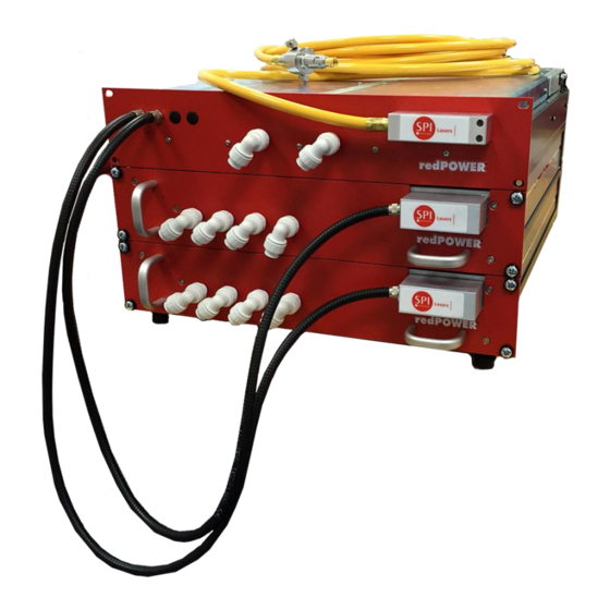
SPI Lasers redPOWER PRISM Instructions For Use Manual (127 pages)
Rack Fiber Laser
Brand:
SPI Lasers
| Category:
Measuring Instruments
| Size: 3 MB
Table of Contents
Table of Contents
5
1 Structure and Scope of These Instructions for Use
11
2 Definition of Symbols and Terms
12
3 Health and Safety
13
General
13
Intended Use of the PRISM Fiber Laser
14
Hazards
14
Compliance
16
Figure 1 WEEE Symbol
16
Labelling
18
Table 1 Safety, Explanatory and Compliance Labels (PRISM FL Modules)
19
Table 2 Safety, Explanatory and Compliance Labels (PRISM HPC Module)
20
Table 3 Safety, Explanatory and Compliance Labels (Fiberview Control Unit)
20
Table 4 Information Labels
21
4 Document References
22
Redpower PRISM Product Tour
22
Key Parts
22
Figure 2 Redpower PRISM Rack Fiber Laser Key Parts
23
Figure 6 Redpower PRISM FL Module Key Features
28
Figure 7 Redpower PRISM Rack Fiber Laser with Auxiliary Equipment
29
Explanation of Order Codes
30
Software Tools
30
Table 5 Explanation of Order Code
30
Auxiliary Equipment
29
Figure 3 PRISM Fiber Laser Rack Key Features
24
Key Features
24
Figure 4 PRISM HPC and Control Module Key Features
25
Figure 5 Optical Connector with Luminator Protection against Back-Reflection
27
6 Getting Started
31
Receiving and Inspection
31
Unpacking and Handling
31
Figure 8 PRISM Rack Fiber Laser in Packing Case as Received
32
Figure 9 Top Tray Removed
32
Figure 10 Flaps Opened Showing Bubble Wrap
33
Figure 11 Bubble Wrap and Top Foam Block Removed
33
Figure 12 Four Point Sling Attached
34
Figure 13 PRISM Fiber Laser on Trolley
34
Unpacking the Beam Delivery Optic
35
7 Installation
35
Safety and Compliance During Installation
35
Figure 14 Packing and Packing Case Ready for Storage
35
Location and Environment
36
Mounting
36
Cooling Water Connections
37
Figure 15 Cooling Water Connections to PRISM HPC Module and PRISM FL Module
38
Table 6 Water Tubing and Fittings
39
Table 7 Water Tubing and Fittings
39
Fiberview Installation
40
Table 8 Water Tubing and Fittings
40
Table 9 Laser Integrator Supplied PC - for Operating Fiberview
40
Electrical Connections
41
Figure 16 Interface Connectors
42
Table 10 Interface Connectors
42
Figure 17 Star Earthing Configuration
43
Figure 18 Bus Bar Connection
45
Table 11 Serial Port Connections
45
Table 12 PL5 Machine Interface Pin out
47
Figure 19 Machine Interface Connections Circuits
49
Figure 20 PL5 Programmable Inputs
50
Figure 21 PL5 Programmable Outputs
51
Table 13 Laser Inputs
52
Table 14 Laser Status Outputs
54
Table 15 BDO Integrity Circuit Connections (When Option Specified)
57
Table 16 Minimum Interface Connection
58
Routing the Beam Delivery Optic
59
Connecting the PIPA-Q Optical Connector to the Process Head
60
Figure 22 Grub Screw Retaining Protective Cap
61
Figure 23 Connector before Removal of Protective Tape
62
Figure 24 Red Dots Aligned
62
Removing PIPA-Q Optical Connector from the Process Head
63
Figure 25 Connector Inserted into Receptacle
63
8 Operating Instructions
64
Before Operation
64
Powering the PRISM Fiber Laser up and down
65
Alarms and Warnings
65
9 Laser Control and Fiberview
66
Overview
66
Basic Operation
66
Figure 26 Fiber Laser Connection Dialog
67
Figure 27 Fiberview Overview Screen
68
Parameter Sets
69
Table 17 Parameter Set Attributes
69
Figure 28 Fiberview Parameter Editor
71
Process Cycles
73
Figure 29 Shape Editor Window
73
Figure 30 Steps Grouped into Process Cycles
74
Figure 31 Fiberview Process Cycle Editor
74
Table 18 Process Cycle Step Attributes
74
Other Settings
75
Basic Control Using Serial Communication
76
Overview
76
Functionality
77
Figure 32 State Transition Diagram
77
Protocol Message References
79
Machine Interface Reference
79
Overview
79
Default Input Functionality
80
Table 19 Default Configuration of Machine Interface Inputs
80
Table 20 Default Configuration of Machine Interface Outputs
80
Figure 33 Moving to STANDBY in Remote Control
82
Figure 34 Moving to off in Remote Control
82
Figure 35 Entering Remote Control (off State, Laser Start Set)
83
Figure 36 Entering Remote Control (STANDBY or on State, Laser Start Clear)
83
Figure 37 Entering Remote Control (STANDBY or on State, Laser Start Set)
83
Figure 38 Moving to on in Remote Control
86
Figure 39 Moving to STANDBY in Remote Control (no Ramp down Time Configured)
87
Figure 40 Moving to STANDBY in Remote Control (Ramp down Time Configured)
87
Figure 41 Moving to on State in Remote Control before the State Has Moved to the STANDBY State
88
Figure 42 Entering Remote Control (STANDBY State, Laser on Input Set)
88
Figure 43 Entering Remote Control (on State, Laser on Input Set)
89
Figure 44 Entering Remote Control (on State, Laser on Input Clear, no Ramp down Time Configured)
89
Figure 45 Entering Remote Control (on State, Laser on Input Clear, Ramp down Time Configured)
90
Figure 46 Starting a Process Cycle in Remote Control
90
Figure 47 Stopping a Process Cycle in Remote Control (no Ramp down Time Configured in Active Step Parameter Step)
91
Figure 48 Stopping a Process Cycle in Remote Control (Ramp down Time Configured in Active Step Parameter Step)
91
Figure 49 Starting a Process Cycle in Remote Control before the State Has Moved to the STANDBY State
92
Figure 50 Entering Remote Control (STANDBY State, Process Cycle Start Input SET)
92
Figure 51 Entering Remote Control (Process Cycle Active, Process Cycle Start Input Set, no Ramp down Time Configured in Active Step Parameter Step)
93
Figure 52 Entering Remote Control (Process Cycle Active, Process Cycle Start Input Set, Ramp down Time Configured in Active Step Parameter Step)
93
Figure 53 Entering Remote Control (STANDBY State, Process Cycle Start Input Set)
94
Figure 54 Entering Remote Control (Process Cycle Active, Process Cycle Start Input CLEAR, no Ramp down Time Configured in Active Step Parameter Step)
94
Figure 55 Entering Remote Control (Process Cycle Active, Process Cycle Start Input CLEAR, Ramp down Time Configured in Active Step Parameter Step)
95
Figure 56 Advancing Process Cycle Steps in Remote Control
96
Figure 57 Advancing Process Cycle Steps in Remote Control (before Process Cycle Wait Is Set)
97
Figure 58 Alarm Reset
98
Figure 59 Alarm Reset When in the on State
99
Figure 60 Edge Trigger Operation(Pulsed Output Only)
100
Default Output Functionality
101
Figure 61 Gated Trigger Operation (Pulsed Output)
101
Figure 62 Gated Trigger Operation (CW Output)
101
Protocol Message References
106
Alarm and Warning Messages
107
Alarm Code Definitions
107
Warning Code Definitions
109
Maintenance
112
Periodic Inspection
112
General Cleaning
112
Cleaning Optics
113
Disposal
113
General Information
113
Trade Marks
113
Licensing
113
Software
113
Table 21 Replacement Windows
113
Warranties
114
Copyright
114
Changes
114
Contact Information
115
General Specifications
115
Table 22 Contact Information
115
Operating Conditions
116
Table 23 Environmental Operating Conditions
116
Non-Operating Conditions
117
Figure 63 Environmental Conditions for Non-Condensing Operation
117
Table 24 Non-Operating Conditions
117
Utility Requirements
118
Table 25 Electrical Requirements
118
Table 26 Power Supply Output Capability Requirements
118
Table 27 Recommended Psus
119
Figure 64 Additional Components for PSU Support
120
Table 24 Cooling Water Requirements
121
Table 25 Cooling Requirements (Laser)
121
Optical Specifications
122
General Optical Specifications
122
Table 23 Required Chiller Capacity
122
Table 26 Cooling Requirements (PIPA-Q Optical Connector)
122
Optical Output - PIPA-Q Optical Connector
123
Table 32 50ΜM Multimode Optical Specifications
123
Table 33 100ΜM Multimode Optical Specifications
123
Mechanical Specifications
124
Overall Dimensions
124
Weight
124
Figure 65 Overall Dimensions
124
Table 34 PRISM Fiber Laser Weights
124
PIPA-Q Optical Connector
125
Figure 66 PIPA-Q Optical Connector
125
Table 35 Mechanical Specifications - PIPA-Q Optical Connector
125
Customer Service
126
Figure 67 Outline Drawing - PIPA-Q Beam Delivery Optic
126
Advertisement
Advertisement
Related Products
SPI Lasers redPOWER QUBE
SPI Lasers redPOWER FVCU
SPI Lasers redPOWER
SPI Lasers Categories
Measuring Instruments
Control Unit
Industrial Equipment
More SPI Lasers Manuals
Login
Sign In
OR
Sign in with Facebook
Sign in with Google
Upload manual
Upload from disk
Upload from URL