Table of Contents
Advertisement
Quick Links
Advertisement
Table of Contents

Related Manuals for SPI Lasers redPOWER PRISM

Summary of Contents for SPI Lasers redPOWER PRISM
- Page 1 PRISM Rack Fiber Laser Instructions for Use...
- Page 2 Laser Integrators are not authorized to modify this PRISM Fiber Laser. © 2016 SPI Lasers UK Ltd. SM-S00496 Revision B 21 October 2016 Commercial in Confidence redPOWER PRISM Rack Fiber Laser Instructions for Use...
- Page 3 Instructions for Use ensure that power to the PRISM Fiber Laser is disconnected. Failure to do so may lead to serious personal injury. © 2016 SPI Lasers UK Ltd. SM-S00496 Revision B 21 October 2016 Commercial in Confidence redPOWER PRISM Rack Fiber Laser Instructions for Use...
- Page 4 IEC/EN 60825-1. © 2016 SPI Lasers UK Ltd. SM-S00496 Revision B 21 October 2016 Commercial in Confidence redPOWER PRISM Rack Fiber Laser Instructions for Use...
-
Page 5: Table Of Contents
Powering the PRISM Fiber Laser Up and Down Alarms and Warnings Laser Control and FiberView Overview Basic Operation Parameter Sets Process Cycles © 2016 SPI Lasers UK Ltd. SM-S00496 Revision B 21 October 2016 Commercial in Confidence redPOWER PRISM Rack Fiber Laser Instructions for Use... - Page 6 Optical Output – PIPA-Q Optical Connector 18.2 Mechanical Specifications 19.1 Overall Dimensions 19.2 Weight 19.3 PIPA-Q Optical Connector Customer Service © 2016 SPI Lasers UK Ltd. SM-S00496 Revision B 21 October 2016 Commercial in Confidence redPOWER PRISM Rack Fiber Laser Instructions for Use...
- Page 7 Figure 5 Optical Connector with Luminator Protection Against Back-Reflection ........27 Figure 6 redPOWER PRISM FL Module Key Features ................ 28 Figure 7 redPOWER PRISM Rack Fiber Laser with Auxiliary Equipment ..........29 Figure 8 PRISM Rack Fiber Laser in Packing Case as Received ............32 Figure 9 Top Tray Removed ........................
- Page 8 Figure 57 Advancing Process Cycle Steps in Remote Control (Before Process Cycle Wait Is Set) ..97 Figure 58 Alarm Reset ..........................98 © 2016 SPI Lasers UK Ltd. SM-S00496 Revision B 21 October 2016 Commercial in Confidence redPOWER PRISM Rack Fiber Laser Instructions for Use...
- Page 9 Table 19 Default Configuration of Machine Interface Inputs ..............80 Table 20 Default Configuration of Machine Interface Outputs ..............80 Table 21 Replacement Windows ......................113 © 2016 SPI Lasers UK Ltd. SM-S00496 Revision B 21 October 2016 Commercial in Confidence redPOWER PRISM Rack Fiber Laser Instructions for Use...
- Page 10 Table 34 PRISM Fiber Laser Weights ....................124 Table 35 Mechanical Specifications – PIPA-Q Optical Connector ............125 © 2016 SPI Lasers UK Ltd. SM-S00496 Revision B 21 October 2016 Commercial in Confidence redPOWER PRISM Rack Fiber Laser Instructions for Use...
-
Page 11: Structure And Scope Of These Instructions For Use
Fiber Laser and made available for reference at the location where the PRISM Fiber Laser is being used. Additional or replacement copies are available from SPI Lasers. These Instructions for Use are divided into the sections below which provide Users with health and safety information before introducing the PRISM Fiber Laser and then guiding them through its installation, operation, maintenance and disposal. -
Page 12: Definition Of Symbols And Terms
Cautions must be observed to prevent personal injury and damage to or destruction of equipment or loss of operational effectiveness. © 2016 SPI Lasers UK Ltd. SM-S00496 Revision B 21 October 2016 Commercial in Confidence redPOWER PRISM Rack Fiber Laser Instructions for Use... -
Page 13: Health And Safety
PRISM Fiber Laser. Access must be restricted to Authorised Personnel. Any local safety requirements for the operation of this equipment must be complied with. © 2016 SPI Lasers UK Ltd. SM-S00496 Revision B 21 October 2016 Commercial in Confidence redPOWER PRISM Rack Fiber Laser Instructions for Use... -
Page 14: Intended Use Of The Prism Fiber Laser
for use in an explosion prone environment SPI Lasers cannot be held liable for any damage resulting from such use. The risk lies entirely with the User. Hazards 3.3.1 Laser Hazards This PRISM Fiber Laser is specifically designed to be a laser for incorporation or integration into other equipment. - Page 15 The PRISM Fiber Laser requires an electrical supply and is water-cooled. Electricity and water, individually or in combination, may create hazards. © 2016 SPI Lasers UK Ltd. SM-S00496 Revision B 21 October 2016 Commercial in Confidence redPOWER PRISM Rack Fiber Laser Instructions for Use...
-
Page 16: Compliance
Within the EU, the PRISM Fiber Laser is CE marked and is supplied with a Declaration of Conformity. The standards which SPI Lasers declares that the PRISM Fiber Laser is in conformity with, and the directives which SPI Lasers declares that the PRISM Fiber Laser complies with the requirements of are listed in the Declaration of Conformity. - Page 17 However SPI Lasers recognises that Laser Integrators may require the integrated laser system to comply with the Directive. SPI Lasers has therefore designed for compliance to parts of the standards listed below which are harmonised to the Machinery Directive: ...
-
Page 18: Labelling
However SPI Lasers recognises that Laser Integrators may require the integrated laser system to comply with the directive. SPI Lasers has therefore designed for compliance to parts of the standards listed below which are harmonised to the EMC Directive: ... -
Page 19: Table 1 Safety, Explanatory And Compliance Labels (Prism Fl Modules)
Laser emission, pipes and cautions label (top panel) Protective conductor terminal indicator (rear panel adjacent to protective conductor terminal) © 2016 SPI Lasers UK Ltd. SM-S00496 Revision B 21 October 2016 Commercial in Confidence redPOWER PRISM Rack Fiber Laser Instructions for Use... -
Page 20: Table 2 Safety, Explanatory And Compliance Labels (Prism Hpc Module)
(rear panel adjacent to protective conductor (Optical connector) terminal) Table 3 Safety, Explanatory and Compliance Labels (FVCU) © 2016 SPI Lasers UK Ltd. SM-S00496 Revision B 21 October 2016 Commercial in Confidence redPOWER PRISM Rack Fiber Laser Instructions for Use... -
Page 21: Table 4 Information Labels
PRISM FL Module identification (rear panel of PRISM FL Module) Address, Patents, WEEE and CE labels (rear panels of FVCU and PRISM FL Modules) © 2016 SPI Lasers UK Ltd. SM-S00496 Revision B 21 October 2016 Commercial in Confidence redPOWER PRISM Rack Fiber Laser Instructions for Use... -
Page 22: Document References
Lasers’ home page: www.spilasers.com. 5 redPOWER PRISM Product Tour The range of redPOWER PRISM Rack Fiber Lasers builds on many years of experience of SPI Lasers in designing, developing and supplying fiber lasers into a wide range of industrial laser processing applications. It gives laser integrators the capability to manufacture industrial laser machines with maximum output power levels from 300W up to many kilowatts. -
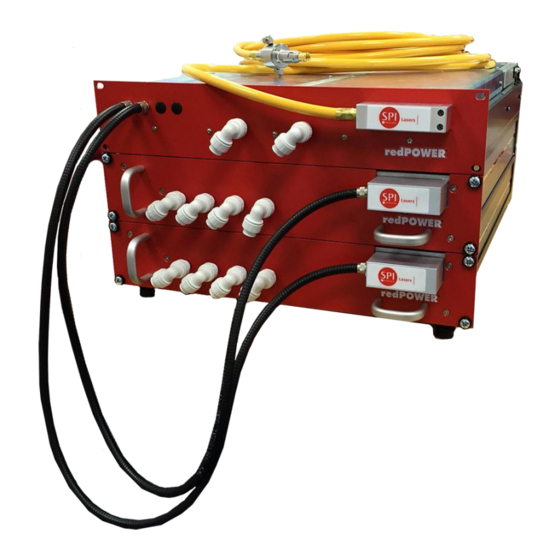
Page 23: Figure 2 Redpower Prism Rack Fiber Laser Key Parts
Figure 2 redPOWER PRISM Rack Fiber Laser Key Parts © 2016 SPI Lasers UK Ltd. SM-S00496 Revision B 21 October 2016 Commercial in Confidence redPOWER PRISM Rack Fiber Laser Instructions for Use... -
Page 24: Key Features
Key Features Figure 3 PRISM Fiber Laser Rack Key Features A schematic block diagram of the range of redPOWER PRISM Rack Fiber Laser racks is shown in Figure 3. In Figure 3 the upper red rectangle represents the PRISM High Power Combiner (HPC) Module (with the FiberView Control Unit positioned behind it), and the lower red rectangles represent PRISM FL modules. -
Page 25: Figure 4 Prism Hpc And Control Module Key Features
The delivery fiber guides the laser power from the PRISM HPC Module into the Laser Integrator’s optics. The multimode fiber is available with different core diameters and is protected by a ruggedized conduit including SPI Lasers’ Fiber Continuity Monitoring System (FCMS) terminated with an industry standard optical connector. The optical connector and ruggedized conduit with FCMS are referred to as the beam delivery optic (BDO). - Page 26 In extreme cases, the PRISM Fiber Laser shuts itself down before damage occurs. © 2016 SPI Lasers UK Ltd. SM-S00496 Revision B 21 October 2016 Commercial in Confidence redPOWER PRISM Rack Fiber Laser Instructions for Use...
-
Page 27: Figure 5 Optical Connector With Luminator Protection Against Back-Reflection
Module is represented by the red rectangle and the cooling water circuit is indicated schematically in blue. US5179610, GB2255199 © 2016 SPI Lasers UK Ltd. SM-S00496 Revision B 21 October 2016 Commercial in Confidence redPOWER PRISM Rack Fiber Laser Instructions for Use... -
Page 28: Figure 6 Redpower Prism Fl Module Key Features
Figure 6 redPOWER PRISM FL Module Key Features Optical Engine The heart of the PRISM Fiber Laser is the optical engine based on SPI Lasers’ proprietary ® GTWave active fiber technology. GTWave takes the optical power of the pump diodes to generate the high beam quality output of the PRISM Fiber Laser. -
Page 29: Auxiliary Equipment
Auxiliary Equipment Figure 7 redPOWER PRISM Rack Fiber Laser with Auxiliary Equipment Installation of the PRISM Fiber Laser within an integrated laser system requires the provision of auxiliary equipment for power and control as shown in Figure 7. Low noise DC power supplies are required to power the pump diodes. -
Page 30: Software Tools
Laser over a serial interface. Operation of the PRISM Fiber Laser using FiberView is described in Section 9. Explanation of Order Codes The redPOWER PRISM Rack Fiber Laser variants covered by these Instructions for Use have order codes: 3000 4500... -
Page 31: Getting Started
Retain all packaging materials until the PRISM Fiber Laser has been commissioned. If anything is missing or defective contact SPI Lasers. See Section 16 for contact details. Unpacking and Handling CAUTION: This PRISM Fiber Laser is heavy and so precautions must be taken when lifting and moving. -
Page 32: Figure 8 Prism Rack Fiber Laser In Packing Case As Received
1. Remove plastic banding and unclip the straps surrounding the packing case. Remove the top tray. Figure 9 Top Tray Removed 2. Open up the flaps. © 2016 SPI Lasers UK Ltd. SM-S00496 Revision B 21 October 2016 Commercial in Confidence redPOWER PRISM Rack Fiber Laser Instructions for Use... -
Page 33: Figure 10 Flaps Opened Showing Bubble Wrap
5. Remove the foam packing pieces from the top of the PRISM Fiber Laser. Attach a four point sling assembly with shackles to the loops at the top of the steel transport frame. © 2016 SPI Lasers UK Ltd. SM-S00496 Revision B 21 October 2016 Commercial in Confidence redPOWER PRISM Rack Fiber Laser Instructions for Use... -
Page 34: Figure 12 Four Point Sling Attached
Figure 13 PRISM Fiber Laser on Trolley 7. Put all foam blocks into the empty packing case and store for future use. © 2016 SPI Lasers UK Ltd. SM-S00496 Revision B 21 October 2016 Commercial in Confidence redPOWER PRISM Rack Fiber Laser Instructions for Use... -
Page 35: Unpacking The Beam Delivery Optic
Before installation reference should be made to Section 3 regarding laser safety, electrical safety, EMC and compliance. When installed, the PRISM Fiber laser and the additional © 2016 SPI Lasers UK Ltd. SM-S00496 Revision B 21 October 2016 Commercial in Confidence redPOWER PRISM Rack Fiber Laser Instructions for Use... -
Page 36: Location And Environment
Section 7.7 and allow sufficient space for correct routing of the conduit. Failure to do so may result in permanent damage to the delivery fiber. © 2016 SPI Lasers UK Ltd. SM-S00496 Revision B 21 October 2016 Commercial in Confidence redPOWER PRISM Rack Fiber Laser Instructions for Use... -
Page 37: Cooling Water Connections
If an external coolant leak occurs and water comes into contact with any of the electrical connectors, allow the PRISM Fiber Laser to dry completely before operating. © 2016 SPI Lasers UK Ltd. SM-S00496 Revision B 21 October 2016 Commercial in Confidence redPOWER PRISM Rack Fiber Laser Instructions for Use... -
Page 38: Figure 15 Cooling Water Connections To Prism Hpc Module And Prism Fl Module
6mm LLDPE or polyurethane tubing. 7.4.3 Cooling Water Fittings The PRISM Fiber Laser is not supplied with water fittings. SPI Lasers recommends that the commonly available push-on John Guest ‘Speedfit’ water connections are used to connect the cooling circuit to the chilled water supply. Ensure that the pipes are clean before adding the connections and that the correct locking clips are used. -
Page 39: Table 6 Water Tubing And Fittings
SMC Part Number Illustration 10mm polyurethane tubing TU1065**-** (for base plate) 6mm polyurethane tubing TU0604**-** (for optical connector) © 2016 SPI Lasers UK Ltd. SM-S00496 Revision B 21 October 2016 Commercial in Confidence redPOWER PRISM Rack Fiber Laser Instructions for Use... -
Page 40: Fiberview Installation
Push the collet square against the fitting. With the collet held in this position the tube can be removed. If this PRISM Fiber Laser is to be transported to a new location, returned to SPI Lasers or placed in storage the PSU must be turned off and disconnected first, and then once the chiller has been disconnected both the PRISM Fiber Laser and the optical connector must be drained of all coolant and blown through with compressed air. -
Page 41: Electrical Connections
The connectors, mounted on the rear panel of the PRISM Fiber Laser as shown in Figure 16, and described in more detail in Table 10. © 2016 SPI Lasers UK Ltd. SM-S00496 Revision B 21 October 2016 Commercial in Confidence redPOWER PRISM Rack Fiber Laser Instructions for Use... -
Page 42: Figure 16 Interface Connectors
7.6.8 SK12 Reserved SK41 - 44 PRISM FL Module Control Interfaces 37-way D-type male Section connector 7.6.4 © 2016 SPI Lasers UK Ltd. SM-S00496 Revision B 21 October 2016 Commercial in Confidence redPOWER PRISM Rack Fiber Laser Instructions for Use... -
Page 43: Figure 17 Star Earthing Configuration
Protective Conductor (Earth) Terminal M8 x 20 Stud Section 7.6.1 7.6.1 Protective Conductor (Earth) Terminal Figure 17 Star Earthing Configuration © 2016 SPI Lasers UK Ltd. SM-S00496 Revision B 21 October 2016 Commercial in Confidence redPOWER PRISM Rack Fiber Laser Instructions for Use... - Page 44 The nut should be tightened to a torque of 12 to 13Nm. © 2016 SPI Lasers UK Ltd. SM-S00496 Revision B 21 October 2016 Commercial in Confidence redPOWER PRISM Rack Fiber Laser Instructions for Use...
-
Page 45: Figure 18 Bus Bar Connection
The pin-out is shown in Table 11. Table 11 Serial Port Connections RS-232 Connections Receive Data input (RX) Transmit Data Output (TX) © 2016 SPI Lasers UK Ltd. SM-S00496 Revision B 21 October 2016 Commercial in Confidence redPOWER PRISM Rack Fiber Laser Instructions for Use... - Page 46 The Machine Interface must be powered by a power supply in range of +15 to +30V (typically +24V) capable of delivering 200mA. Power is provided by connecting the external supply © 2016 SPI Lasers UK Ltd. SM-S00496 Revision B 21 October 2016 Commercial in Confidence redPOWER PRISM Rack Fiber Laser Instructions for Use...
-
Page 47: Table 12 Pl5 Machine Interface Pin Out
Digital Input Common Return path GNDEXT GNDEXT External 0 V DC GNDEXT GNDEXT External 0 V DC © 2016 SPI Lasers UK Ltd. SM-S00496 Revision B 21 October 2016 Commercial in Confidence redPOWER PRISM Rack Fiber Laser Instructions for Use... - Page 48 The Machine Interface inputs and outputs are provided as sourcing only. Figure 19 below shows the configuration and connection method. © 2016 SPI Lasers UK Ltd. SM-S00496 Revision B 21 October 2016 Commercial in Confidence redPOWER PRISM Rack Fiber Laser Instructions for Use...
-
Page 49: Figure 19 Machine Interface Connections Circuits
Figure 19 Machine Interface Connections Circuits © 2016 SPI Lasers UK Ltd. SM-S00496 Revision B 21 October 2016 Commercial in Confidence redPOWER PRISM Rack Fiber Laser Instructions for Use... -
Page 50: Figure 20 Pl5 Programmable Inputs
Figure 20 PL5 Programmable Inputs © 2016 SPI Lasers UK Ltd. SM-S00496 Revision B 21 October 2016 Commercial in Confidence redPOWER PRISM Rack Fiber Laser Instructions for Use... -
Page 51: Figure 21 Pl5 Programmable Outputs
If this input is clear when entering Remote Control and the PRISM Fiber Laser is in the ON state, the PRISM Fiber Laser will go to the OFF state. © 2016 SPI Lasers UK Ltd. SM-S00496 Revision B 21 October 2016 Commercial in Confidence redPOWER PRISM Rack Fiber Laser Instructions for Use... -
Page 52: Table 13 Laser Inputs
True: Sets PRISM Fiber Laser to ON or starts a defined process cycle (if laser already in STANDBY) © 2016 SPI Lasers UK Ltd. SM-S00496 Revision B 21 October 2016 Commercial in Confidence redPOWER PRISM Rack Fiber Laser Instructions for Use... - Page 53 19. Table 14 shows the full list of functions that can be configured to apply to any of OUT0 - OUT6 as shown in Table 12. © 2016 SPI Lasers UK Ltd. SM-S00496 Revision B 21 October 2016 Commercial in Confidence redPOWER PRISM Rack Fiber Laser Instructions for Use...
-
Page 54: Table 14 Laser Status Outputs
Selected (Bit 2) Parameter Set / Process Cycle Selected (Bit 3) Parameter Set / Process Cycle Selected (Bit 4) © 2016 SPI Lasers UK Ltd. SM-S00496 Revision B 21 October 2016 Commercial in Confidence redPOWER PRISM Rack Fiber Laser Instructions for Use... - Page 55 The active pulse shape must also be set into EPC mode using FiberView. (Refer to Section 9.3.7.) There are two modes for this function: © 2016 SPI Lasers UK Ltd. SM-S00496 Revision B 21 October 2016 Commercial in Confidence redPOWER PRISM Rack Fiber Laser Instructions for Use...
- Page 56 It is understood that this will be done in a manner certified to © 2016 SPI Lasers UK Ltd. SM-S00496 Revision B 21 October 2016 Commercial in Confidence redPOWER PRISM Rack Fiber Laser Instructions for Use...
-
Page 57: Table 15 Bdo Integrity Circuit Connections (When Option Specified)
Must be linked to pin 8 Must be linked to pin 6 SK99 – Service Monitor 7.6.10 SK-99 is provided for use by SPI Lasers service personnel only. © 2016 SPI Lasers UK Ltd. SM-S00496 Revision B 21 October 2016 Commercial in Confidence... -
Page 58: Table 16 Minimum Interface Connection
FCMS pins on the user interface connector the Prism Fibre Laser is disabled and the industrial laser machine is put in a safe state. © 2016 SPI Lasers UK Ltd. SM-S00496 Revision B 21 October 2016 Commercial in Confidence redPOWER PRISM Rack Fiber Laser Instructions for Use... -
Page 59: Routing The Beam Delivery Optic
(e.g. jigs, fixtures, production parts, workstation walls, floors, robot parts). In dynamic applications (where BDO and process head move), additionally: © 2016 SPI Lasers UK Ltd. SM-S00496 Revision B 21 October 2016 Commercial in Confidence redPOWER PRISM Rack Fiber Laser Instructions for Use... -
Page 60: Connecting The Pipa-Q Optical Connector To The Process Head
© 2016 SPI Lasers UK Ltd. SM-S00496 Revision B 21 October 2016 Commercial in Confidence redPOWER PRISM Rack Fiber Laser Instructions for Use... -
Page 61: Figure 22 Grub Screw Retaining Protective Cap
Remove the protective cap, shown in Figure 22, from the connector. It can be pulled straight off. © 2016 SPI Lasers UK Ltd. SM-S00496 Revision B 21 October 2016 Commercial in Confidence redPOWER PRISM Rack Fiber Laser Instructions for Use... -
Page 62: Figure 23 Connector Before Removal Of Protective Tape
Pull the sleeve out by 2mm Whilst in the pulled-out position rotate the locking sleeve until hand tight Tighten by hand only © 2016 SPI Lasers UK Ltd. SM-S00496 Revision B 21 October 2016 Commercial in Confidence redPOWER PRISM Rack Fiber Laser Instructions for Use... -
Page 63: Removing Pipa-Q Optical Connector From The Process Head
Immediately after the optical connector is removed the protective cap must be refitted. The process head receiver should also be plugged to prevent dust entry. © 2016 SPI Lasers UK Ltd. SM-S00496 Revision B 21 October 2016 Commercial in Confidence redPOWER PRISM Rack Fiber Laser Instructions for Use... -
Page 64: Operating Instructions
Laser hazards, safety procedures and correct use of related safety equipment. © 2016 SPI Lasers UK Ltd. SM-S00496 Revision B 21 October 2016 Commercial in Confidence redPOWER PRISM Rack Fiber Laser Instructions for Use... -
Page 65: Powering The Prism Fiber Laser Up And Down
PRISM FL Module and allowing operation to continue until the problem can be rectified. © 2016 SPI Lasers UK Ltd. SM-S00496 Revision B 21 October 2016 Commercial in Confidence redPOWER PRISM Rack Fiber Laser Instructions for Use... -
Page 66: Laser Control And Fiberview
FiberView is an advanced laser control system offering many features not available in other products. However the protocol for controlling redPOWER Fiber Lasers is available from SPI Lasers to allow users to integrate control of redPOWER Fiber Lasers into an overall system controller. -
Page 67: Figure 26 Fiber Laser Connection Dialog
It is possible to have more than one instance of FiberView running on a single PC, with each instance controlling a separate redPOWER Fiber Laser. © 2016 SPI Lasers UK Ltd. SM-S00496 Revision B 21 October 2016 Commercial in Confidence redPOWER PRISM Rack Fiber Laser Instructions for Use... -
Page 68: Figure 27 Fiberview Overview Screen
The effect is to ‘chop’ the CW output into a series of pulses. © 2016 SPI Lasers UK Ltd. SM-S00496 Revision B 21 October 2016 Commercial in Confidence redPOWER PRISM Rack Fiber Laser Instructions for Use... -
Page 69: Parameter Sets
ON to the STANDBY state, with a maximum of 10s © 2016 SPI Lasers UK Ltd. SM-S00496 Revision B 21 October 2016 Commercial in Confidence redPOWER PRISM Rack Fiber Laser Instructions for Use... - Page 70 Parameter Sets can be edited using the Parameter Editor. Select by Parameter Editor Tab, or View – Windows – Parameter Set Programming on Menu Bar. © 2016 SPI Lasers UK Ltd. SM-S00496 Revision B 21 October 2016 Commercial in Confidence redPOWER PRISM Rack Fiber Laser Instructions for Use...
-
Page 71: Figure 28 Fiberview Parameter Editor
Sets the pulse width, in µs, for the pulse width duration for the Single Sector Pulse and User Defined Shape output styles. Maximum duration that can be set is 1s. © 2016 SPI Lasers UK Ltd. SM-S00496 Revision B 21 October 2016 Commercial in Confidence redPOWER PRISM Rack Fiber Laser Instructions for Use... - Page 72 Pulse Shape. Any node on the Shape can be selected and dragged to a new position to alter the shape. © 2016 SPI Lasers UK Ltd. SM-S00496 Revision B 21 October 2016 Commercial in Confidence redPOWER PRISM Rack Fiber Laser Instructions for Use...
-
Page 73: Process Cycles
Figure 30 shows Steps grouped into Process Cycles. The Process Cycles contain from one to 16 Steps. © 2016 SPI Lasers UK Ltd. SM-S00496 Revision B 21 October 2016 Commercial in Confidence redPOWER PRISM Rack Fiber Laser Instructions for Use... -
Page 74: Figure 30 Steps Grouped Into Process Cycles
Parameter Set Parameter This field is used to reference any of the 50 available Reference Parameter Sets © 2016 SPI Lasers UK Ltd. SM-S00496 Revision B 21 October 2016 Commercial in Confidence redPOWER PRISM Rack Fiber Laser Instructions for Use... -
Page 75: Other Settings
Maintenance Tab and then MCIF from its toolbar, or from the Menu bar: View – Windows – Maintenance – Machine Interface. © 2016 SPI Lasers UK Ltd. SM-S00496 Revision B 21 October 2016 Commercial in Confidence redPOWER PRISM Rack Fiber Laser Instructions for Use... -
Page 76: Basic Control Using Serial Communication
This section explains how to start and stop the PRISM Fiber Laser using the serial protocol over either an RS-232 or Ethernet connection. © 2016 SPI Lasers UK Ltd. SM-S00496 Revision B 21 October 2016 Commercial in Confidence redPOWER PRISM Rack Fiber Laser Instructions for Use... -
Page 77: Functionality
Three commands can be issued to change the state. (The other states are controlled by the sequencing.) © 2016 SPI Lasers UK Ltd. SM-S00496 Revision B 21 October 2016 Commercial in Confidence redPOWER PRISM Rack Fiber Laser Instructions for Use... - Page 78 The ramp up duration is determined by the active parameter set. The ON state is left after receiving a Laser STANDBY command. © 2016 SPI Lasers UK Ltd. SM-S00496 Revision B 21 October 2016 Commercial in Confidence redPOWER PRISM Rack Fiber Laser Instructions for Use...
-
Page 79: Protocol Message References
This section describes setting up the Machine Interface on the redPOWER PRISM Fiber Laser using the default configuration. SM-S00499, Fiber... -
Page 80: Default Input Functionality
Only operational in Remote Control. o Takes the state from OFF to STANDBY under Remote Control © 2016 SPI Lasers UK Ltd. SM-S00496 Revision B 21 October 2016 Commercial in Confidence redPOWER PRISM Rack Fiber Laser Instructions for Use... - Page 81 Associated default functions o Laser STANDBY - Output Function o Remote Status - Output Function Sequence diagrams: © 2016 SPI Lasers UK Ltd. SM-S00496 Revision B 21 October 2016 Commercial in Confidence redPOWER PRISM Rack Fiber Laser Instructions for Use...
-
Page 82: Figure 33 Moving To Standby In Remote Control
Figure 34 Moving to OFF in Remote Control Note: There is a small switching delay before the Laser Start is acted on (<1ms) © 2016 SPI Lasers UK Ltd. SM-S00496 Revision B 21 October 2016 Commercial in Confidence redPOWER PRISM Rack Fiber Laser Instructions for Use... -
Page 83: Figure 35 Entering Remote Control (Off State, Laser Start Set)
Figure 36 Entering Remote Control (STANDBY or ON State, Laser Start Clear) Figure 37 Entering Remote Control (STANDBY or ON State, Laser Start Set) © 2016 SPI Lasers UK Ltd. SM-S00496 Revision B 21 October 2016 Commercial in Confidence redPOWER PRISM Rack Fiber Laser Instructions for Use... - Page 84 Start input is either not configured or configured and SET), the state will remain the ON state. In this case the Laser ON input is level sensitive. © 2016 SPI Lasers UK Ltd. SM-S00496 Revision B 21 October 2016 Commercial in Confidence redPOWER PRISM Rack Fiber Laser Instructions for Use...
- Page 85 Laser ON / Process Cycle Active - Output Function o Remote Status - Output Function Sequence diagrams © 2016 SPI Lasers UK Ltd. SM-S00496 Revision B 21 October 2016 Commercial in Confidence redPOWER PRISM Rack Fiber Laser Instructions for Use...
-
Page 86: Figure 38 Moving To On In Remote Control
There is a small switching delay before Laser ON is acted on (<1ms) and Laser ON status is SET or CLEARED © 2016 SPI Lasers UK Ltd. SM-S00496 Revision B 21 October 2016 Commercial in Confidence redPOWER PRISM Rack Fiber Laser Instructions for Use... -
Page 87: Figure 39 Moving To Standby In Remote Control (No Ramp Down Time Configured)
(No Ramp Down Time Configured) Figure 40 Moving to STANDBY in Remote Control (Ramp Down Time Configured) © 2016 SPI Lasers UK Ltd. SM-S00496 Revision B 21 October 2016 Commercial in Confidence redPOWER PRISM Rack Fiber Laser Instructions for Use... -
Page 88: Figure 41 Moving To On State In Remote Control Before The State Has Moved To The Standby State
Before the State has Moved to the STANDBY State Figure 42 Entering Remote Control (STANDBY State, Laser ON Input Set) © 2016 SPI Lasers UK Ltd. SM-S00496 Revision B 21 October 2016 Commercial in Confidence redPOWER PRISM Rack Fiber Laser Instructions for Use... -
Page 89: Figure 43 Entering Remote Control (On State, Laser On Input Set)
(ON State, Laser ON Input Set) Figure 44 Entering Remote Control (ON State, Laser ON Input Clear, No Ramp Down Time Configured) © 2016 SPI Lasers UK Ltd. SM-S00496 Revision B 21 October 2016 Commercial in Confidence redPOWER PRISM Rack Fiber Laser Instructions for Use... -
Page 90: Figure 45 Entering Remote Control (On State, Laser On Input Clear, Ramp Down Time Configured)
Process Cycle Start can be asserted at any time to start a Process Cycle as long as the state is the STANDBY state. © 2016 SPI Lasers UK Ltd. SM-S00496 Revision B 21 October 2016 Commercial in Confidence redPOWER PRISM Rack Fiber Laser Instructions for Use... -
Page 91: Figure 47 Stopping A Process Cycle In Remote Control (No Ramp Down Time Configured In Active Step Parameter Step)
Figure 48 Stopping a Process Cycle in Remote Control (Ramp Down Time Configured in Active Step Parameter Step) © 2016 SPI Lasers UK Ltd. SM-S00496 Revision B 21 October 2016 Commercial in Confidence redPOWER PRISM Rack Fiber Laser Instructions for Use... -
Page 92: Figure 49 Starting A Process Cycle In Remote Control Before The State Has Moved To The Standby State
Figure 49 Starting a Process Cycle in Remote Control Before the State has Moved to the STANDBY State Figure 50 Entering Remote Control (STANDBY State, Process Cycle Start Input SET) © 2016 SPI Lasers UK Ltd. SM-S00496 Revision B 21 October 2016 Commercial in Confidence redPOWER PRISM Rack Fiber Laser Instructions for Use... -
Page 93: Figure 51 Entering Remote Control (Process Cycle Active, Process Cycle Start Input Set, No Ramp Down Time Configured In Active Step Parameter Step)
(Process Cycle Active, Process Cycle Start Input Set, Ramp Down Time Configured in Active Step Parameter Step) © 2016 SPI Lasers UK Ltd. SM-S00496 Revision B 21 October 2016 Commercial in Confidence redPOWER PRISM Rack Fiber Laser Instructions for Use... -
Page 94: Figure 53 Entering Remote Control (Standby State, Process Cycle Start Input Set)
Figure 54 Entering Remote Control (Process Cycle Active, Process Cycle Start Input CLEAR, No Ramp Down Time Configured in Active Step Parameter Step) © 2016 SPI Lasers UK Ltd. SM-S00496 Revision B 21 October 2016 Commercial in Confidence redPOWER PRISM Rack Fiber Laser Instructions for Use... -
Page 95: Figure 55 Entering Remote Control (Process Cycle Active, Process Cycle Start Input Clear, Ramp Down Time Configured In Active Step Parameter Step)
An output function can be configured on the Machine Interface to indicate that the Process Cycle is waiting for a Step input in order to advance. © 2016 SPI Lasers UK Ltd. SM-S00496 Revision B 21 October 2016 Commercial in Confidence redPOWER PRISM Rack Fiber Laser Instructions for Use... -
Page 96: Figure 56 Advancing Process Cycle Steps In Remote Control
The Process Cycle Wait output will clear once the Step input command has been processed. It is not synchronised with the clearing of the Step input. © 2016 SPI Lasers UK Ltd. SM-S00496 Revision B 21 October 2016 Commercial in Confidence redPOWER PRISM Rack Fiber Laser Instructions for Use... -
Page 97: Figure 57 Advancing Process Cycle Steps In Remote Control (Before Process Cycle Wait Is Set)
© 2016 SPI Lasers UK Ltd. SM-S00496 Revision B 21 October 2016 Commercial in Confidence redPOWER PRISM Rack Fiber Laser Instructions for Use... -
Page 98: Figure 58 Alarm Reset
The alarm condition must be cleared before resetting it otherwise the alarm may reoccur following the reset. © 2016 SPI Lasers UK Ltd. SM-S00496 Revision B 21 October 2016 Commercial in Confidence redPOWER PRISM Rack Fiber Laser Instructions for Use... -
Page 99: Figure 59 Alarm Reset When In The On State
The output can only be Triggered up to the frequency configured in the active parameter set. © 2016 SPI Lasers UK Ltd. SM-S00496 Revision B 21 October 2016 Commercial in Confidence redPOWER PRISM Rack Fiber Laser Instructions for Use... -
Page 100: Figure 60 Edge Trigger Operation(Pulsed Output Only)
- Input Function Sync - Output Function Sequence diagrams Figure 60 Edge Trigger Operation(Pulsed Output Only) © 2016 SPI Lasers UK Ltd. SM-S00496 Revision B 21 October 2016 Commercial in Confidence redPOWER PRISM Rack Fiber Laser Instructions for Use... -
Page 101: Default Output Functionality
SET when the state is the STANDBY state. o CLEAR when the state is in the OFF state. © 2016 SPI Lasers UK Ltd. SM-S00496 Revision B 21 October 2016 Commercial in Confidence redPOWER PRISM Rack Fiber Laser Instructions for Use... - Page 102 Machine Interface Laser ON input function (SET under Remote Control), or a Laser ON serial command message. © 2016 SPI Lasers UK Ltd. SM-S00496 Revision B 21 October 2016 Commercial in Confidence redPOWER PRISM Rack Fiber Laser Instructions for Use...
- Page 103 Basic Function Description o SET when in Remote Control. o CLEAR when t in Local Control. © 2016 SPI Lasers UK Ltd. SM-S00496 Revision B 21 October 2016 Commercial in Confidence redPOWER PRISM Rack Fiber Laser Instructions for Use...
- Page 104 - Input Function 11.3.5 Warning (Output Function ID 8) Default connection o PL5 pin number 21 © 2016 SPI Lasers UK Ltd. SM-S00496 Revision B 21 October 2016 Commercial in Confidence redPOWER PRISM Rack Fiber Laser Instructions for Use...
- Page 105 Process Cycle is waiting for a Step input in order to continue. o CLEAR at any other time. o Operational in both Local and Remote Control. © 2016 SPI Lasers UK Ltd. SM-S00496 Revision B 21 October 2016 Commercial in Confidence redPOWER PRISM Rack Fiber Laser Instructions for Use...
-
Page 106: Protocol Message References
Refer to SM-S00499, Fiber Laser Serial Communications Protocol, for the exact structure and implementation of the above serial protocol commands. © 2016 SPI Lasers UK Ltd. SM-S00496 Revision B 21 October 2016 Commercial in Confidence redPOWER PRISM Rack Fiber Laser Instructions for Use... -
Page 107: Alarm And Warning Messages
Fiber Failure 8m13 BDO Open 8m14 BDO Short 8m15 Humidity 8m16 Internal Communications Failure 8m17 Unexpected Emission © 2016 SPI Lasers UK Ltd. SM-S00496 Revision B 21 October 2016 Commercial in Confidence redPOWER PRISM Rack Fiber Laser Instructions for Use... - Page 108 3m02 PRISM FL Module fault 3m03 PRISM FL Module communications failure 3m04 PRISM FL Module communications failure © 2016 SPI Lasers UK Ltd. SM-S00496 Revision B 21 October 2016 Commercial in Confidence redPOWER PRISM Rack Fiber Laser Instructions for Use...
-
Page 109: Warning Code Definitions
© 2016 SPI Lasers UK Ltd. SM-S00496 Revision B 21 October 2016 Commercial in Confidence redPOWER PRISM Rack Fiber Laser Instructions for Use... - Page 110 High diode tray temperature 1148 Modulator fault detected 1150 Shape data has been reset 1151 Segment data has been reset © 2016 SPI Lasers UK Ltd. SM-S00496 Revision B 21 October 2016 Commercial in Confidence redPOWER PRISM Rack Fiber Laser Instructions for Use...
- Page 111 Using default Machine Interface configuration 12.2.6 PSU Zone Warnings Code Description 7150 PSU not present. 7151 PSU charge fault © 2016 SPI Lasers UK Ltd. SM-S00496 Revision B 21 October 2016 Commercial in Confidence redPOWER PRISM Rack Fiber Laser Instructions for Use...
-
Page 112: Maintenance
Clean only with a clean damp cloth and if any labels become displaced contact SPI Lasers immediately for replacements. © 2016 SPI Lasers UK Ltd. SM-S00496 Revision B 21 October 2016 Commercial in Confidence redPOWER PRISM Rack Fiber Laser Instructions for Use... -
Page 113: Cleaning Optics
The SPI Lasers logo, SPI, GTWave, redPOWER and redENERGY are trademarks (registered or applied for) of SPI Lasers in at least one of the United States of America, the United Kingdom, the European Community and China, and in various other territories throughout the world. -
Page 114: Warranties
SPI Lasers, except as allowed under applicable copyright laws. The information contained herein is confidential and is the property of SPI Lasers. No part may be reproduced, disclosed or used except as authorised by contract or other written permission. The copyright and the foregoing restriction on reproduction and use extend to all media in which the information may be embodied. -
Page 115: Contact Information
PRISM Fiber Laser, please read this section to ensure all requirements are understood. © 2016 SPI Lasers UK Ltd. SM-S00496 Revision B 21 October 2016 Commercial in Confidence redPOWER PRISM Rack Fiber Laser Instructions for Use... -
Page 116: Operating Conditions
80% then the cooling water temperature should be above 26°C, and preferably 30°C, to prevent condensation. © 2016 SPI Lasers UK Ltd. SM-S00496 Revision B 21 October 2016 Commercial in Confidence redPOWER PRISM Rack Fiber Laser Instructions for Use... -
Page 117: Non-Operating Conditions
0 – 95 (non-condensing) Humidity (Storage) % RH Below 2°C the cooling circuit must be drained to prevent freezing © 2016 SPI Lasers UK Ltd. SM-S00496 Revision B 21 October 2016 Commercial in Confidence redPOWER PRISM Rack Fiber Laser Instructions for Use... -
Page 118: Utility Requirements
Preferably, the power supply should be certified against at least the requirements of IEC 60950 2 edition amendment A1by a Nationally Recognized Testing Laboratory © 2016 SPI Lasers UK Ltd. SM-S00496 Revision B 21 October 2016 Commercial in Confidence redPOWER PRISM Rack Fiber Laser Instructions for Use... -
Page 119: Table 27 Recommended Psus
SPI Lasers has not seen any need for additional capacitive support on the TDK-Lambda power supply. SPI Lasers has also found that the Meanwell PSUs can produce significant output ripple at their internal power factor correction and main output switching frequencies. This ripple does not prevent successful operation, but it may be fed through to the monitoring outputs of the PRISM Fiber Laser. -
Page 120: Figure 64 Additional Components For Psu Support
Trials have shown that the use of common mode filter chokes on the power cables can minimise the effect of this ripple on the performance of the PRISM Fiber Laser. SPI Lasers recommends using four EMI cores part number M-981, article number 12704, from Magnatec GmbH for each PRISM FL Module. -
Page 121: Table 24 Cooling Water Requirements
Input Pressure Flow Rate l/min/kW Per PRISM FL Module At 20°C water temperature. Pressure Drop PRISM FL Module © 2016 SPI Lasers UK Ltd. SM-S00496 Revision B 21 October 2016 Commercial in Confidence redPOWER PRISM Rack Fiber Laser Instructions for Use... -
Page 122: Optical Specifications
Central Emission Wavelength 1075 ±7 Rated output power for variants with bare fiber is increased by 4% © 2016 SPI Lasers UK Ltd. SM-S00496 Revision B 21 October 2016 Commercial in Confidence redPOWER PRISM Rack Fiber Laser Instructions for Use... -
Page 123: Optical Output - Pipa-Q Optical Connector
10%-90% rated power, 20kHz modulation frequency, 50% duty cycle 90%-10% rated power, 20kHz modulation frequency, 50% duty cycle © 2016 SPI Lasers UK Ltd. SM-S00496 Revision B 21 October 2016 Commercial in Confidence redPOWER PRISM Rack Fiber Laser Instructions for Use... -
Page 124: Mechanical Specifications
The approximate weights of PRISM Fiber Lasers of different rated powers are given in Table Table 35 PRISM Fiber Laser Weights Rated Power Weight Comment 86kg 4.5kW 120kg © 2016 SPI Lasers UK Ltd. SM-S00496 Revision B 21 October 2016 Commercial in Confidence redPOWER PRISM Rack Fiber Laser Instructions for Use... -
Page 125: Pipa-Q Optical Connector
Connector Diameter 34.0 Cable Diameter 11.9 Cable Material (External) Anti-abrasion polyurethane (yellow) Minimum Bend Radius Maximum Tensile Load © 2016 SPI Lasers UK Ltd. SM-S00496 Revision B 21 October 2016 Commercial in Confidence redPOWER PRISM Rack Fiber Laser Instructions for Use... -
Page 126: Customer Service
In the unlikely event that the PRISM Fiber Laser requires attention outside the scope of the maintenance requirements as detailed in Section 9, contact SPI Lasers for advice on further on-site fault diagnosis and/or return of the PRISM Fiber Laser. Contact information is given in Section 16. - Page 127 SPI Lasers. Accurate details, diagnosis and comments in the documentation reduce turnaround time for repair at SPI Lasers. On request, SPI Lasers will supply a report detailing faults found and repairs carried out necessary to return the PRISM Fiber Laser to full operational specification.
Need help?
Do you have a question about the redPOWER PRISM and is the answer not in the manual?
Questions and answers