Sign In
Upload
Manuals
Brands
Spectra-Physics Manuals
Industrial Equipment
Tsunami
Spectra-Physics Tsunami Ti:Sapphire Manuals
Manuals and User Guides for Spectra-Physics Tsunami Ti:Sapphire. We have
1
Spectra-Physics Tsunami Ti:Sapphire manual available for free PDF download: User Manual
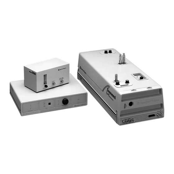
Spectra-Physics Tsunami User Manual (238 pages)
Mode-locked Ti:sapphire Laser
Brand:
Spectra-Physics
| Category:
Industrial Equipment
| Size: 3 MB
Table of Contents
Preface
3
Environmental Specifications
5
CE Electrical Equipment Requirements
5
FCC Regulations
5
Table of Contents
7
Table of Contents
9
Warning Conventions
15
Standard Units
17
Abbreviations
19
Unpacking and Inspection
21
Chapter 1: Introduction
23
The Tsunami System
23
Figure 1-1: the Tsunami Laser System (Chiller Not Shown)
23
System Configurations
24
Conversions
24
Upgradeability
25
Patents
25
Chapter 2: Laser Safety
27
Precautions for the Safe Operation of
27
Class IV-High Power Lasers
27
Figure 2-2: Folded Metal Beam Target
28
Interlocks
29
Figure 2-3: Laser Head Shutter Interlock
29
Maintenance Required to Keep this Laser Product in Compliance with Center for Devices and Radio Logical Health (CDRH) Regulations
30
CD/CDRH Radiation Control Drawing
31
Figure 2-4: Tsunami Radiation Control Drawing (Refer to Labels on Next Page)
31
CE/CDRH Warning Labels
32
Figure 2-5: CE/CDRH Warning Labels
32
Label Translations
33
Table 2-1: Label Translations
33
CE Declaration of Conformity
34
Sources for Additional Information
36
Laser Safety Standards
36
Equipment and Training
37
Chapter 3: Laser Description
39
General Overview
39
Ti:sapphire Laser Theory
40
Figure 3-1: Absorption and Emission Spectra of Ti:sapphire
40
Pumping Optimization
41
Tsunami Laser Description
42
Pump Laser
42
The Folded Cavity
42
Figure 3-3: Beam Path for Tsunami Models 3960 and 3941 Femtosecond Configurations
42
A/O Modulator (AOM)
43
Wavelength Tuning Characteristics
43
Figure 3-4: Beam Path for Tsunami Model 3950 Picosecond Configuration
43
Figure 3-5: Tsunami Femtosecond Tuning Curves for Broadband Optics When Pumped by the Various Millennia Diode-Pumped Cw Lasers Shown
44
Figure 3-6: Tsunami Picosecond Tuning Curves for Broadband Optics When Pumped by the Various Millennia Diode-Pumped CW Lasers Shown
45
Figure 3-7: Tsunami Femtosecond Tuning Curves for the Optics Sets Shown When Pumped by a 10 W Millennia Xs Diode-Pumped CW Laser
45
Figure 3-8: Tsunami Femtosecond Tuning Curves for the Optics Sets Shown When Pumped by a 5 W Millennia Vs Diode-Pumped CW Laser
46
Figure 3-9: Tsunami Picosecond Tuning Curves for the Optics Sets Shown When Pumped by a 10 W Millennia Xs Diode-Pumped CW Laser
46
Wavelength Selection
47
Figure 3-10: Tsunami Picosecond Tuning Curves for the Optics Sets Shown When Pumped by a 5 W Millennia Vs Diode-Pumped CW Laser
47
Pulse Width Selection
48
Purging the Tsunami
48
Figure 3-11: Transmittance Vs. Wavelength for Oxygen and Water Vapor
49
Specifications
50
Table 3-1: Tsunami Femtosecond Broadband Performance When Pumped by a Millennia Laser
50
Table 3-2: Tsunami Picosecond Broadband Performance When Pumped by a Millennia Laser
51
Table 3-3: Tsunami Femtosecond Performance When Pumped by a Millennia Laser
52
Table 3-4: Tsunami Picosecond Performance When Pumped by a Millennia Laser
53
Table 3-5: Electrical, Mechanical and Physical Specifications
54
Table 3-6: Environmental Specifications
54
Table 3-7: Lok-To-Clock Tsunami Specifications
55
Outline Dimensions for Models 3941, 3950 and 3960
56
Figure 3-12: Outline Drawing
56
Chapter 4: Controls, Indicators and Connections
57
Introduction
57
Laser Head Controls
57
Figure 4-1: Tsunami External Laser Head Controls. Not All Controls Are Present on some Models
57
Input Bezel Connections
58
Control Panel
58
Mechanical Controls
59
Figure 4-2: Tsunami Laser Head Control Panel
59
Opto-Mechanical Controls All Systems
60
Figure 4-3: Laser Head, Rod Side View
61
Figure 4-4: Laser Head, Output Coupler Side View
62
Opto-Mechanical Controls Fs Configuration
63
Opto-Mechanical Controls Ps Configuration
64
Model 3955 Electronics Module Controls
64
Front Panel
64
Figure 4-5: Model 3955 Electronics Module Front Panel Controls and Indicators
64
Rear Panel
65
Figure 4-6: Model 3955 Electronics Module Rear Panel Controls and Connections
65
Figure 4-7: Typical MONITOR Signal
66
Figure 4-8: Typical SYNC Signal
66
Model 3910 Purge Unit Controls
67
Figure 4-9: Model 3910 Regulator/Filter Purge Unit
67
Chapter 5: Installation
69
Laser Installation
69
Installing the Pump Laser
69
Figure 5-1: Typical Tsunami Head and Pump Laser Head Layout
69
Initial Placement of the Tsunami Laser Head
70
Aligning the Tsunami Laser Head to the Pump Beam
70
Installing the Chiller
71
Figure 5-2: Typical System Interconnect Diagram
72
Removing the Chiller Hoses from the Laser Head and Chiller
73
Installing the Model 3910 Regulator/Filter Purge Unit
73
Removing the Purge Line from the Laser Head and Model 3910
74
Installing the Tsunami Model 3955 Electronics Module
74
Installing the GTI (Ps Configuration)
75
Figure 5-3: the Gires-Tournois Interferometer (GTI)
76
Verifying Cable Connections
77
Figure 5-4: Tsunami Laser Head PC Board Connections
77
Figure 5-5: Photodiode PC Board
78
Chapter 6 Alignment
79
Equipment Required
80
Front-End Alignment
80
Figure 6-1: Tsunami Fs Configuration
81
Figure 6-2: Tsunami Ps Configuration
81
Table 6-1: Pump Power Requirements
82
Cavity Alignment for a FS System
85
Table 6-2: Pump Power Requirements
85
Figure 6-8: the Slit Control
87
Figure 6-9: Four Prism/Four Mirror Section of Fs Laser Cavity
88
Aligning the A/O Modulator (AOM)
90
Figure 6-10: AOM, Output Coupler, Photodiode PC Board, and Beam Splitter
90
Establish Modelocking
91
Optimizing Modelocking
91
Cavity Alignment for a PS System
92
Aligning the A/O Modulator (AOM)
94
Establish Modelocking
95
Figure 6-14: Precursor to Modelocking a Ps Pulse as Seen Using an Autocorrelator and Oscilloscope
96
Optimize Modelocking
97
Selecting, Installing and Aligning the Birefringent Filter
98
Figure 6-15: the Birefringent Filter
98
Table 6-3: Bi-Fi Alignment for Picosecond Operation
99
Aligning the Photodiode PC Board
100
Figure 6-16: Photodiode PC Board
100
Test for Proper Modelocking
101
Table 6-4: Photodiode Part Numbers
101
Converting between Non-Overlapping Optics Sets
103
Figure 6-17: Tsunami Fs Configuration
103
Figure 6-18: Tsunami Ps Configuration
104
Figure 6-20: Tsunami Laser Head PC Board Connections
106
Figure 6-21: the Gires-Tournois Interferometer (GTI)
107
Changing the Prism Setting (Fs Systems Only)
108
Table 6-5: Vertical Mirror Adjustment (Turns) for Changing Wavelengths
109
Table 6-6: Nominal Distance from Beam to Apex (See Figure 6-22)
109
Converting between Overlapping Optics Sets
111
Converting between Fs and Ps Configurations
112
Requirements for Conversion
112
Fs to Ps Conversion
113
Ps to Fs Conversion
115
Coarse Phase Adjustment and Changing the RF and Photodiode Cables
118
Chapter 7: Operation
121
System Start-Up
121
Figure 7-1: Transmittance Vs. Wavelength for Oxygen and Water Vapor
122
Optimizing Laser Output
123
Figure 7-2: Tsunami External Laser Head Controls
123
Modelocking the Laser
124
Selecting Wavelength, Fs Configuration (Using the Slit)
125
Selecting Wavelength, Ps Configuration (Using the Birefringent Filter)
126
Operating in the Broad Fs Regime (150 Fs - 1 Ps)
127
Tsunami System Verification
127
Conversion for Broad Femtosecond Operation
127
Operating in the Broad Picosecond Regime
128
Tsunami System Verification
128
Conversion for Long Picosecond Operation
129
Table 7-1: Bi-Fi Selection for Broad Picosecond Operation
129
Operating with the Ultrashort Pulse Option (USP)
130
Operating in the Sub-35 Fs Regime
130
Troubleshooting in the Sub-35 Fs Regime
133
Operating with Lok-To-Clock
134
System Shut-Down
135
Chapter 8: Lok-To-Clock Electronics
137
Functional Overview
137
Figure 8-1: the Lok-To-Clock Phase-Locked Loop
137
System Controls
138
Front Panel
138
Figure 8-2: Model 3930 Electronics Module Front Panel Controls and Indicators
138
Rear Panel
139
Figure 8-3: Model 3930 Electronics Module Rear Panel Controls and Connections
140
Figure 8-4: Lok-To-Clock Fs System Block Diagram
141
Figure 8-5: Lok-To-Clock Ps System Block Diagram
142
Installing the Model 3930
143
Operation Notes
144
Start-Up
145
Shut down
145
Typical Set-Ups
145
Example 1: Synchronizing Pulses from Two LTC Tsunami Lasers
145
Figure 8-6: Synchronization of Two Lok-To-Clock Tsunami Lasers
146
Example 2: Synchronizing Pulses from a Mode-Locked Laser with an LTC Tsunami
148
Figure 8-8: Synchronization of a Standard Tsunami Laser to a Lok-To-Clock Tsunami Laser
148
Operating a Model 3941D/3950D/3960D Without the Model 3930
150
Lok-To-Clock Computer Interface
152
The Model 3930 Command Set
152
Table 8-1: the SCPI Command Set
152
General Comments on the SCPI Standard Protocol
153
Differences between the Lok-To-Clock Implementation and the SCPI Standard
157
Chapter 9: Maintenance
159
Notes on the Cleaning of Laser Optics
159
Equipment Required
160
Standard Cleaning Procedures
160
General Procedures for Cleaning Optics
161
Figure 9-1: Drop and Drag Method
162
Figure 9-2: Lens Tissue Folded for Cleaning
162
Removing and Cleaning Tsunami Optics
163
Brewster Windows
164
Prisms (Fs Configuration)
164
Ti:sapphire Rod
164
Birefringent Filter (Ps Configuration)
165
Pump Mirrors P1 and P2
166
Figure 9-3: Birefringent Filter
166
GTI (Ps Configuration)
168
A/O Modulator (AOM)
168
Beam Splitter
170
Routing Mirrors
170
Replacing Filters in the Model 3910 Purge Unit
170
Figure 9-5: Underside of Model 3910 Showing Filter Assembly Placement and Orientation
171
Chapter 10: Options and Accessories
173
Options
173
Ultrashort (< 50 Fs) Pulse Option
173
Ultrashort (< 35 Fs) Pulse Option
173
Broad Femtosecond Pulse Option
173
Broad Picosecond Pulse Option
173
76 Mhz Option
173
Lok-To-Clock ® System
174
Accessories
174
Model 409-08 Scanning Autocorrelator
174
Model 3980 Frequency Doubler/Pulse Selector
174
Model 3931
174
GWU Harmonic Generator System
174
Opal ® System
174
Gwu-Opo-Ps
175
Regenerative Amplifier Systems
175
Accessory and Conversion Optics Sets
176
Table 10-1: Standard Fs Tsunami Mirrors-Millennia Xs Pump Laser
176
Table 10-2: Standard Fs Tsunami Mirrors-Millennia Vs Pump Laser
176
Table 10-3: Standard Ps Tsunami Mirrors-Millennia Xs Pump Laser
176
Table 10-4: Standard Ps Tsunami Mirrors-Millennia Vs Pump Laser
176
Table 10-5: Broadband Fs Tsunami Mirrors-Millennia Xs Pump Laser
177
Table 10-6: Broadband Fs Tsunami Mirrors-Millennia Viiis Pump Laser
177
Table 10-7: Broadband Fs Tsunami Mirrors-Millennia Vs Pump Laser
177
Table 10-8: Broadband Ps Tsunami Mirrors-Millennia Xs Pump Laser
177
Table 10-9: Broadband Ps Tsunami Mirrors-Millennia Viiis Pump Laser
177
Table 10-10: Broadband Ps Tsunami Mirrors-Millennia Vs Pump Laser
177
Table 10-11: Fs Tsunami-Wavelength Conversion Sets
178
Table 10-12: Fs Tsunami-Wavelength Conversion Sets
178
Table 10-13: Ps Tsunami-Wavelength Conversion Sets
179
Table 10-14: Ps Tsunami-Wavelength Conversion Sets
179
Table 10-15: Fs to Ps Tsunami-Wavelength Conversion Sets
180
Table 10-16: Ps to Fs Tsunami-Wavelength Conversion Sets
180
Table 10-17: GTI and Bi-Fi for Broad Pulse Operation
181
Table 10-18: Photodiode PC Board
181
Chapter 11 Service and Repair
183
Troubleshooting Guide
183
Generic Troubleshooting (Non-Lok-To-Clock Systems)
184
Troubleshooting LTC Systems
190
Table 11-1: Optics
191
Table 11-2: Hardware
191
Table 11-3: Model 3910 Purge Unit Filter Hardware
191
Chapter 12 Customer Service
193
Warranty
193
Return of the Instrument for Repair
194
Service Centers
195
Appendix A Modelocking
197
General
197
Modelocking Techniques
198
Figure A-1: Typical Output of a Mode-Locked Laser, Where L Is the Cavity Length and C Is the
198
Regenerative Modelocking in the Tsunami
200
Group Velocity Dispersion (GVD
201
Nonlinear Effects
202
GVD Compensation
203
And Produces a Pulse Which Has no Chirp
204
Appendix B Pulse Width Measurement
207
Introduction
207
The Autocorrelation Technique
207
Measurement of Ultrashort Pulses
207
Signal Interpretation
210
Table B-1 : Second-Order Autocorrelation Functions and Time-Bandwidth Products for
210
GVD Compensation in Measurement of Ultrashort Pulses
211
Calculating Pulse Broadening
213
Table B-3: Positive Dispersion Values @ 800 Nm
213
Table B-4: Negative Dispersion Values @ 800 Nm
213
CW Breakthrough
215
Table B-5: Recommended Monochromator/CCD Components
217
Appendix C: Setting the Line Voltage Switch
219
Appendix D: Lok-To-Clock Labview Interface
221
Overview
221
Setup
221
Controls Description
222
Appendix E Material Safety Data Sheets
223
Notes
231
Report Form for Problems and Solutions
237
Advertisement
Advertisement
Related Products
Spectra-Physics Categories
Laboratory Equipment
Measuring Instruments
Industrial Equipment
More Spectra-Physics Manuals
Login
Sign In
OR
Sign in with Facebook
Sign in with Google
Upload manual
Upload from disk
Upload from URL