
Summary of Contents for Spectra-Physics Tsunami
- Page 1 Tsunami Mode-locked Ti:sapphire Laser User’s Manual The Solid-State Laser Company 1335 Terra Bella Avenue Mountain View, CA 94043 Part Number 0000-232A, Rev. D June 2002...
-
Page 3: Preface
The “Introduction” contains a brief description of the various Tsunami laser configurations and conversions from fs to ps operation (if your system is reconfigurable) and vice versa, and how to adapt the Tsunami for Lok-to- ® Clock operation. - Page 4 Appendix D provides general information on the Lok-to-Clock LabView Interface. Appendix E contains Material Safety Data Sheets for products used with this unit. The Tsunami laser is designed to be pumped by a Spectra-Physics Millen- ® series diode-pumped solid-state laser. The specifications listed in this manual are only for units pumped by these lasers.
-
Page 5: Environmental Specifications
Environmental Specifications CE Electrical Equipment Requirements For information regarding the equipment needed to provide the electrical service listed under “Service Requirements” at the end of Chapter 3, please refer to specification Plug, Outlet and Socket Couplers for Indus- EN-309, “ trial Uses listed in the official Journal of the European Communities. -
Page 7: Table Of Contents
The Tsunami System ........ - Page 8 Installing the Tsunami Model 3955 Electronics Module ....... . .5-6...
-
Page 9: Table Of Contents
Typical Set-ups ..............8-9 Example 1: Synchronizing Pulses from Two LTC Tsunami Lasers ......8-9 Example 2: Synchronizing Pulses from a mode-locked laser with an LTC Tsunami . - Page 10 Regenerative Modelocking in the Tsunami ........
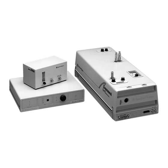
- Page 11 Figure 1-1: The Tsunami Laser System (chiller not shown) ....... .
- Page 12 Figure 6-20: Tsunami Laser Head PC Board Connections ....... . .6-28...
- Page 13 Table 8-1: The SCPI Command Set ..........8-16 Table 10-1 : Standard fs Tsunami Mirrors—Millennia Xs Pump Laser ......10-4 Table 10-2 : Standard fs Tsunami Mirrors—Millennia Vs Pump Laser .
- Page 14 Table 10-15 : fs to ps Tsunami–Wavelength Conversion Sets .......10-8...
-
Page 15: Warning Conventions
Warning Conventions The following warnings are used throughout this manual to draw your attention to situations or procedures that require extra attention. They warn of hazards to your health, damage to equipment, sensitive procedures, and exceptional circumstances. All messages are set apart by a thin line above and below the text as shown here. -
Page 17: Standard Units
Standard Units The following units, abbreviations, and prefixes are used in this Spectra- Physics manual: Quantity Unit Abbreviation mass kilogram length meter time second frequency hertz force newton energy joule power watt electric current ampere electric charge coulomb electric potential volt Ω... -
Page 19: Abbreviations
Abbreviations The following is a list of abbreviations used in this manual: alternating current acousto-optic modulator active pulse mode locking antireflection bi-fi birefringent filter CDRH Center of Devices and Radiological Health colliding pulse mode locking continous wave direct current electro-optic femtosecond or 10 second Gires-Toutnois Interferometer... -
Page 21: Unpacking And Inspection
Warning! Spectra-Physics considers itself responsible for the safety, reliability, and performance of the Tsunami laser only under the following condi- tions: • All field installable options, modifications, or repairs are performed by persons trained and authorized by Spectra-Physics. - Page 22 • Two hoses (cooling system water supply and return lines) • Three foot clamps with hardware for mounting the Tsunami laser head • A tool kit containing: • Allen (hex) ball drivers for optimizing laser output •...
-
Page 23: Chapter 1: Introduction
Gires- Tournois interferometer ( ) which is required for picosecond operation. ® The optional Model 3930 Lok-to-Clock electronics module can be added to any of the three systems to allow the output from the Tsunami to operate... -
Page 24: System Configurations
The Tsunami system includes dust tubes to enclose the pump beam path for improved performance and for personal safety. Also included are a tool kit, a separate box for the (if you ordered a ps system), and a box for the mirror (if you ordered the optional Lok-to-Clock system). -
Page 25: Upgradeability
Model 3941D, 3950D or 3960D. However, the initial upgrade work must be performed by an authorized Spectra-Physics service engi- neer. The Model 3941 Tsunami Lite system is designed as a fs-only unit and can- not be converted. For more information on upgrades, please contact your Spectra-Physics sales representative. - Page 26 Tsunami Mode-Locked Ti:sapphire Laser...
-
Page 27: Chapter 2: Laser Safety
Diffuse as well as specular reflections cause severe skin or eye damage. Because the Tsunami laser emits cw and pulsed infrared radiation, it is Danger! extremely dangerous to the eye. Infrared radiation passes easily through... -
Page 28: Figure 2-2: Folded Metal Beam Target
Tsunami Mode-Locked Ti:sapphire Laser • Establish a controlled access area for laser operation. Limit access to those trained in the principles of laser safety. • Post prominent warning signs near the laser operation area (Figure 2-1). • Set up experiments so the laser beam is either above or below eye level. -
Page 29: Interlocks
Laser Safety Interlocks Because the energy to drive the lasing process in the Tsunami comes from another laser and not from an internal source (such as electrical discharge), the interlock differs slightly from that of other lasers. The Tsunami laser system has only one interlock: the shutter interlock on the laser head. -
Page 30: Maintenance Required To Keep This Laser Product In Compliance With Center For Devices And Radio Logical Health (Cdrh) Regulations
Maintenance Required to Keep this Laser Product in Compliance with Center for Devices and Radio logical Health ( ) Regulations CDRH The actions listed below are required in order to keep the Tsunami laser product in compliance with Regulations. CDRH... -
Page 31: Cd/Cdrh Radiation Control Drawing
Model 3955, Back Panel EXT TIMING LOOP /\/\/\ RS-232-C 115/230V~60/50Hz ADJUST 1.0/0.5A 0451-7233 100V PHOTODIODE PHOTODIODE REF÷ 8 80 MHz 120V TO HEAD 220V 240V Model 3930, Back Panel Figure 2-4: Tsunami Radiation Control Drawing (refer to labels on next page) -
Page 32: Ce/Cdrh Warning Labels
Tsunami Mode-Locked Ti:sapphire Laser CE/CDRH Warning Labels Spectra-Physics 1344 TERRA BELLA AVENUE VISIBLE AND/OR INVISIBLE* MT. VIEW, CALIFORNIA 94039 LASER RADIATION MANUFACTURED: AVOID EYE OR SKIN EXPOSURE TO DIRECT OR SCATTERED RADIATION. YEAR MONTH CLASS 4 LASER PRODUCT POWER, WAVELENGTH(S) AND PULSE... -
Page 33: Label Translations
Laser Safety Label Translations For safety, the following translations are provided for non-English speak- ing personnel. The number in parenthesis in the first column corresponds to the label number listed on the previous page. Table 2-1: Label Translations Label # French German Spanish... -
Page 34: Ce Declaration Of Conformity
1330 Terra Bella Avenue P.O. Box 7013 Mountain View, CA. 94039-7013 United States of America declare under sole responsibility that the: Tsunami Mode-locked, Ti:sapphire Laser with Controller Manufactured after February 21, 1997 meets the intent of “Directive for Electromagnetic Compatibil- 89/336/EEC ity.”... - Page 35 1330 Terra Bella Avenue P.O. Box 7013 Mountain View, CA. 94039-7013 United States of America declare under sole responsibility that the Tsunami Mode-locked, Ti:sapphire Laser with Controller Manufactured after February 21, 1997 meets the intent of “Directive , the Low Voltage directive.” 73/23/EEC...
-
Page 36: Sources For Additional Information
Tsunami Mode-Locked Ti:sapphire Laser Sources for Additional Information The following are some sources for additional information on laser safety standards, safety equipment, and training. Laser Safety Standards Safe Use of Lasers (Z136.1: 1993) American National Standards Institute ( ANSI 11 West 42... -
Page 37: Equipment And Training
Laser Safety Equipment and Training Laser Safety Guide Laser Institute of America 12424 Research Parkway, Suite 125 Orlando, FL 32826 Tel: (407) 380-1553 Laser Focus World Buyer's Guide Laser Focus World Penwell Publishing 10 Tara Blvd., 5 Floor Nashua, NH 03062 Tel: (603) 891-0123 Lasers and Optronics Buyer's Guide Lasers and Optronics... - Page 38 Tsunami Mode-Locked Ti:sapphire Laser 2-12...
-
Page 39: Chapter 3: Laser Description
Chapter 3 Laser Description General Overview The Tsunami ® laser head contains the Ti:sapphire rod and the optics that form the resonator cavity. Elements include pump beam mirrors, rod focus- ing mirrors, an output coupler ( ), a high reflector ( ), beam folding mirrors, dispersion control elements, and tuning elements. -
Page 40: Ti:sapphire Laser Theory
Tsunami Mode-Locked Ti:sapphire Laser The separate chiller unit keeps the Tsunami Ti:sapphire rod at a constant temperature for long-term stable performance. The chiller is fully described in its own manual shipped with the system. Ti:sapphire Laser Theory The Ti titanium ion is responsible for the laser action of Ti:sapphire. -
Page 41: Pumping Optimization
Laser Description 1000 Wavelength (nm) Figure 3-2: Energy level structure of Ti in sapphire Pumping Optimization For continuous-wave (CW) pumping, there is one basic requirement for lasing action: the unsaturated round-trip CW gain must exceed the round- trip loss from all sources. The cw gain is obtained by having a high inver- sion density and an adequate length of Ti:sapphire material. -
Page 42: Tsunami Laser Description
V, VIII or X diode-pumped, cw solid-state laser operating in power mode. A Millennia X can supply 10 W of 532 nm power to Tsunami while the Millennia V provides 5 W. Performance values given in this manual are provided for various Millennia pump powers. For optimum performance, the optics need to be changed to accommodate different pump powers. -
Page 43: A/O Modulator (Aom)
A concave focusing mirror used at the proper angle induces astigmatism in the pump beam that matches that of the Tsunami cavity mode. The result is a laser with high conversion efficiency and good beam quality. -
Page 44: Figure 3-5: Tsunami Femtosecond Tuning Curves For Broadband Optics When Pumped By The Various Millennia Diode-Pumped Cw Lasers Shown
Tsunami Mode-Locked Ti:sapphire Laser The wavelength tuning range of the Tsunami laser is 675 nm to 1100 nm (i.e., the rod and system are capable of continuous tuning over this range). However, to facilitate stable, high output performance at any wavelength within this range, several optimized, over-lapping mirror sets are available. -
Page 45: Figure 3-6: Tsunami Picosecond Tuning Curves For Broadband Optics When Pumped By The Various Millennia Diode-Pumped Cw Lasers Shown
Millennia diode-pumped CW lasers shown. Standard Midrange Long Blue Extra Long 1010 1050 1090 Wavelength (nm) Figure 3-7: Tsunami femtosecond tuning curves for the optics sets shown when pumped by a 10 W Millennia Xs diode-pumped CW laser. -
Page 46: Figure 3-8: Tsunami Femtosecond Tuning Curves For The Optics Sets Shown When Pumped By A 5 W Millennia Vs Diode-Pumped Cw Laser
5 W Millennia Vs diode-pumped CW laser. Standard Midrange Long Blue Extra Long 1010 1050 1090 Wavelength (nm) Figure 3-9: Tsunami picosecond tuning curves for the optics sets shown when pumped by a 10 W Millennia Xs diode-pumped CW laser. -
Page 47: Wavelength Selection
The method used for wavelength tuning depends on whether the laser is configured for fs or ps operation (Figure 3-3 and Figure 3-4). fs systems. The fs Tsunami laser is wavelength tuned using a prism sequence and a slit. This sequence provides a region in the cavity where the wavelengths are spatially spread. -
Page 48: Pulse Width Selection
“Mode Locking: Group Velocity Dispersion.” Purging the Tsunami The Tsunami head is sealed so it can be purged. The Model 3910 regulator/ filter purge unit is provided for filtering and drying bottled nitrogen gas. Purging the laser cavity with this gas not only eliminates the typical prob- lems associated with dust and contamination, but also prevents tuning dis- continuities caused by oxygen and water vapor. -
Page 49: Figure 3-11: Transmittance Vs. Wavelength For Oxygen And Water Vapor
Laser Description Wave Number (cm ) 14000 13000 12000 11000 10000 1.00 0.99 0.98 0.97 1000 1100 Wavelength (nm) Figure 3-11: Transmittance vs. Wavelength for Oxygen and Water Vapor. 3-11... -
Page 50: Specifications
< 1 mrad Polarization > 500:1 vertical Specifications subject to change without notice and only apply when the Tsunami is pumped by a Spectra-Physics Mil- lennia X or V diode-pumped CW laser. Specifications apply to operation using the optional X-Long optics set. -
Page 51: Table 3-2: Tsunami Picosecond Broadband Performance When Pumped By A Millennia Laser
< 1 mrad Polarization > 500:1 vertical Specifications subject to change without notice and only apply when the Tsunami is pumped by a Spectra-Physics Mil- lennia X or V diode-pumped CW laser. Specifications apply to operation using the optional X-Long optics set. -
Page 52: Table 3-3: Tsunami Femtosecond Performance When Pumped By A Millennia Laser
Percent power drift in any 2-hour period with less than a ±1°C temperature change after a 1-hour warm-up. Pulse widths below 50 fs and between 150 fs and 1 ps are also available. Contact your local Spectra-Physics represen- tative for more details. -
Page 53: Table 3-4: Tsunami Picosecond Performance When Pumped By A Millennia Laser
Beam Divergence, full angle <.06 mrad Polarization >500:1 vertical Specifications subject to change without notice and only apply when the Tsunami is pumped by a Spectra-Physics Millennia X or V diode-pumped CW laser. Specifications apply to operation at the wavelength noted. A sech pulse shape (0.65 deconvolution factor) is used to determine the pulse width as measured with a Spectra-... -
Page 54: Table 3-5: Electrical, Mechanical And Physical Specifications
Tsunami Mode-Locked Ti:sapphire Laser Table 3-5: Electrical, Mechanical and Physical Specifications Electrical Model 3955 Electronics Module 220 Vac, 0.5 A/110 Vac, 1.0 A Model 3930 Electronics Module 220 Vac, 0.5 A/110 Vac, 1.0 A Chiller (Refer to the instruction manual supplied with unit) -
Page 55: Table 3-7: Lok-To-Clock Tsunami Specifications
Timing jitter (rms) Specifications subject to change without notice and only apply when the Lok-to-Clock Tsu- nami system is pumped by a Spectra-Physics Millennia laser. For output characteristics, refer to the tables at the end of Chapter 3. Measured over 1 second with respect to the internal 80 MHz oscillator over a 2- hour period after a 1-hour warm-up and less than ±1°C temperature change. -
Page 56: Outline Dimensions For Models 3941, 3950 And 3960
Tsunami Mode-Locked Ti:sapphire Laser Outline Dimensions for Models 3941, 3950 and 3960 12.24 310,9 3.37 3.37 32.00 85,6 85,6 812,8 7.56 192,0 4.66 4.43 118,4 112,5 4.00 0.9 to 1.5 101,6 2.12 8.00 26.00 2.75 23 to 38 203,2 660,4... -
Page 57: Chapter 4: Controls, Indicators And Connections
Horiz. Vert. GTI (ps) or High Reflector (fs) LTC Photodiode (LTC PD) Connector Water Inlet Connector Purge Inlet Connector Purge Bleed Valve Water Outlet Connector Figure 4-1: Tsunami external laser head controls. Not all controls are present on some models. -
Page 58: Input Bezel Connections
Tsunami Mode-Locked Ti:sapphire Laser Input Bezel Connections The input bezel connections attach to the Model 3910 purge unit (optional on the Model 3941), the chiller, the optional Model 3930 Lok-to-Clock electronics module, and the standard Model 3955 electronics module. Refer to Figure 4-1 or Figure 4-3. -
Page 59: Mechanical Controls
Mechanical Controls Shutter—blocks the pump beam at the entrance to the Tsunami laser head housing to prevent the Tsunami from lasing. When the cover is in place, it holds the shutter open for normal operation. When it is removed, the shut- ter closes automatically, blocking the input beam. -
Page 60: Opto-Mechanical Controls All Systems
—is driven by the Model 3955 electronics module to insure proper pulsing at start-up and, when the optional Model 3930 Lok-to-Clock mod- ule is present, assists in synchronizing Tsunami pulses to another source. has pitch and Bragg-angle controls. output coupler ( )—one of two cavity end mirrors. -
Page 61: Figure 4-3: Laser Head, Rod Side View
Controls, Indicators and Connections This page is a position holder. Substitute the B-size, Figure 4-3 fold-out for this page and the next. Figure 4-3: Laser Head, Rod Side View... -
Page 62: Figure 4-4: Laser Head, Output Coupler Side View
Tsunami Mode-Locked Ti:sapphire Laser This page is a position holder. Substitute the B-size, Figure 4-4 fold-out for this page and the previous one. Figure 4-4: Laser Head, Output Coupler Side View... -
Page 63: Opto-Mechanical Controls Fs Configuration
Configuration The following describes the opto-mechanical controls that are present only on Tsunami lasers configured for femtosecond only operation (Model 3941) or on picosecond systems designed for conversion to femtosecond operation (Model 3960). Refer to Figure 4-3 and Figure 4-4. -
Page 64: Opto-Mechanical Controls Ps Configuration
Tsunami Mode-Locked Ti:sapphire Laser Opto-Mechanical Controls ps Configuration The following describes the opto-mechanical controls present on Tsunami lasers that are configured for picosecond only operation (Model 3950) or on femtosecond systems designed for conversion to picosecond operation (Model 3960). Refer to Figure 4-3 and Figure 4-4. -
Page 65: Rear Panel
Controls, Indicators and Connections Fine control—adjusts the phase relationship between the PHASE signal and the photodiode signal to provide a pulse-locking mechanism. Its adjustment range is about 100 ps. Adjust this control to sync the mode locker to the pulse rate. If you use cables other than those shipped with the system, or if you NOTE: convert from a ps to a fs configuration, or vice versa, or convert from extra-... -
Page 66: Figure 4-7: Typical Monitor Signal
A typical waveform is shown in MONITOR Figure 4-8. This signal can also drive other Spectra-Physics products, such as the Model 3985 pulse selector. This is a negative signal. The signal amplitude shown is approximate and depends on operating wavelength, power and photodiode response. -
Page 67: Model 3910 Purge Unit Controls
Model 3910 Purge Unit Controls The Model 3910 contains oil and air filters and a molecular-sieve assembly to dry and clean nitrogen gas for purging the Tsunami laser head. It has one control and two connectors. Refer toFigure 4-9. knob—used to set the laser head purge rate (gas flow) FLOW ADJUST from 0.3 to 3.0 m... - Page 68 Tsunami Mode-Locked Ti:sapphire Laser 4-12...
-
Page 69: Chapter 5: Installation
Most of the tools and equipment you need to set up the Tsunami and pump lasers are in your accessory kit. Some pieces, like the for ps-configured systems, are in separate containers. -
Page 70: Initial Placement Of The Tsunami Laser Head
This completes the installation of the pump laser. Initial Placement of the Tsunami Laser Head 1. Place the Tsunami laser head on the table parallel to the pump laser as shown in Figure 5-1, and position it so its input window is roughly in the same plane as the output window of the pump laser. -
Page 71: Installing The Chiller
Detailed information on installing and starting the chiller can be found in the manual supplied with the chiller. 1. Place the chiller on the floor close enough to the Tsunami laser head so that the 3.5 m long hoses will reach from the chiller connectors on the back of the unit to the Tsunami front bezel connectors and the Millen- nia pump laser as shown in Figure 5-2. -
Page 72: Figure 5-2: Typical System Interconnect Diagram
The hose connections are not polarized. Finger tight is enough: do not overtighten. Water should first flow to the Millennia laser, then to the Tsunami. To do this, a third hose with quick-disconnects on each end is required in order to bring water from the Millennia to the Tsunami laser. -
Page 73: Removing The Chiller Hoses From The Laser Head And Chiller
PTFE outgassed impurities into the cavity that may degrade system perfor- mance and/or cause damage to the optical coatings. 3. Connect the purge line from the Model 3910 purge unit to the Tsunami laser head. Use the 3.5 m purge line provided to connect the Model 3910 to PTFE ®*... -
Page 74: Removing The Purge Line From The Laser Head And Model 3910
To release the purge line from the Model 3910 purge unit, press inward on the wire clip-spring while gently pulling on the hose. Installing the Tsunami Model 3955 Electronics Module If you have a Lok-to-Clock system, install the Model 3930 at this time. -
Page 75: Installing The Gti (Ps Configuration)
If RF and/or photodiode cables other than those shipped with Tsunami are used, an adjustment for cable length is required. Refer to Chapter 6, “Alignment: Coarse Phase Adjustment...”... -
Page 76: Figure 5-3: The Gires-Tournois Interferometer (Gti)
Tsunami Mode-Locked Ti:sapphire Laser The pc board on the floor of the laser head contains high voltage for Danger! driving the . Verify the Model 3955 electronics module is off to dis- able this board before continuing. 1. Remove the from its shipping container and inspect it for damage. -
Page 77: Verifying Cable Connections
GTI SMA Module for GTI Signal Connector Signal Connector Connector J (10-Pin) (25-Pin) Figure 5-4: Tsunami Laser Head PC Board Connections This completes the installation. Verifying Cable Connections 1. Verify the modulator ( ) heater cable is connected to on the laser head pc board. -
Page 78: Figure 5-5: Photodiode Pc Board
Direct back reflections into the oscillator can cause serious instabilities Caution! in laser performance. Please take precautions to avoid such reflections. This completes the Tsunami and pump laser installation. If you have a Lok- to-Clock system, refer to Chapter 8 for installation and operating instruc- tions. -
Page 79: Chapter 6 Alignment
Chapter 6 Alignment ® This chapter contains several alignment procedures for the Tsunami laser. Most have been categorized into two sections, one for fs alignment and one for ps. A Spectra-Physics service representative will perform the initial cavity alignment and cleaning when he installs your new laser. Thereafter, there should be little need to do a full alignment. -
Page 80: Equipment Required
, or the prisms in a Caution! fs Tsunami laser. These optics are prealigned at the factory and are not to be disturbed until specifically told to do so elsewhere in this manual. A service call may be required if disturbed. -
Page 81: Figure 6-1: Tsunami Fs Configuration
Optic part numbers are written on the barrel of each optic along with a v-shaped arrow that points to the coated, intracavity surface. Always close the shutter when replacing optics. 4. Clean the Tsunami windows. Refer to Chapter 9, “Maintenance: Removing and Cleaning Tsunami Optics: Brewster Windows.” Fast Photodiode... -
Page 82: Table 6-1: Pump Power Requirements
5. Open both laser shutters and check the alignment of the pump beam entering the Tsunami laser. Refer to Chapter 5, “Installation: Installing the Pump Laser” and “Installing the Tsunami Laser Head,” for initial alignment information. Close the shutter when done. 6. Verify pump laser performance. - Page 83 ” on the gradation scale (Figure 6-4). 9. Align pump beam steering mirror a. Verify the pump laser is set for minimum current. b. Open the pump laser and Tsunami shutters. c. Center the pump beam on (Figure 6-5) using the vertical and horizontal adjustments on the routing mirrors.
- Page 84 Tsunami Mode-Locked Ti-sapphire Laser Setscrew On bottom, opposite this hole. Translation Screw Vert. Horiz. Horiz. Vert. Pump Pump Steering Mirror Focusing Mirror Figure 6-5: Pump Mirrors 11. Align cavity focus mirror Adjust vertically and horizontally to direct the small amount of...
-
Page 85: Cavity Alignment For A Fs System
Alignment 2 – 3 mm Focused M Image Image and M Images Overlapped Figure 6-6: Images Focused on the White Card f. Move the translation stage until the vertically-oriented elliptical image displayed on the card becomes focused. Hold the translation stage in place and loosen its setscrew (located over the dovetail slide, Figure 6-3). - Page 86 Tsunami Mode-Locked Ti-sapphire Laser fs Position ps Position Input Bezel Output Bezel ps Position fs Position Figure 6-7: Locations of for fs operation. 2. Align fold mirrors a. Verify are in their correct positions for fs operation (Fig- ure 6-7).
-
Page 87: Figure 6-8: The Slit Control
Alignment Do not place the card between the optical components from Caution! The refraction of fluorescence through the prisms causes the spots to spread in the vertical plane and, thus, are not representative of the laser beam path. DO NOT adjust through , nor the prism angles. -
Page 88: Figure 6-9: Four Prism/Four Mirror Section Of Fs Laser Cavity
A service call may be required if disturbed. 3. Align a. Place a power meter in the Tsunami output beam path as a beam block. b. Place a white card with a 2.5 mm diameter hole in it between... - Page 89 Alignment 5. Iterate Steps 2 through 4 until the beam is centered on and power is maximized. Avoid parallax error when noting beam position on the mirrors by put- ting the line-of-sight normal to the mirror axis. It is important that the beam is centered on because this restores the alignment of the prism sequence so that the beam passes through all the prisms at...
-
Page 90: Aligning The A/O Modulator (Aom)
Tsunami Mode-Locked Ti-sapphire Laser Aligning the A/O Modulator (AOM) Output Coupler (M Positioning Controls Horz. Vert. AOM Pitch Control Photodiode PC Board AOM Aperture Window Mounting Screws (2) Beam Splitter AOM Mounting Setscrews (2) Output Coupler (M AOM Horizontal Angle Control... -
Page 91: Establish Modelocking
Figure 6-11. 2. Optimize Tsunami output power. Place a power meter in the Tsunami beam path and adjust for maximum output power as specified in Step 4 on page 6-10. light bar level indicator on the Model 3955 front PHOTODIODE panel should indicate maximum for standard wavelengths and >30%... -
Page 92: Cavity Alignment For A Ps System
(Bandwidth is subject to pump power level as well as dispersion compensation in the cavity.) 4. Repeat Steps 1 through 3 until the Tsunami pulse is optimized and the test in Step 4 of “Test for Proper Modelocking” later in this chapter is successful. - Page 93 Remove the white card. 3. Align a. Place a power meter in the Tsunami output beam path as a beam block. b. Place a white card with a 2.5 mm diameter hole in it between...
-
Page 94: Aligning The A/O Modulator (Aom)
If the laser modelocks properly, you do not have to perform this procedure. Proper alignment is critical for both ps and fs Tsunami lasers. This procedure assures good beam alignment for optimum modelocking. -
Page 95: Establish Modelocking
Alignment Output Coupler (M Positioning Controls Horz. Vert. AOM Pitch Control Photodiode PC Board AOM Aperture Window Mounting Screws (2) Beam Splitter AOM Mounting Setscrews (2) Output Coupler (M AOM Horizontal Angle Control Figure 6-13: , Output Coupler, Photodiode PC Board, and Beam Splitter Place a white card between and the beam splitter, and use the edge of the card to detect the position of the beam. -
Page 96: Figure 6-14: Precursor To Modelocking A Ps Pulse As Seen Using An Autocorrelator And Oscilloscope
Tsunami Mode-Locked Ti-sapphire Laser Figure 6-14: Precursor to modelocking a ps pulse as seen using an autocorrelator and oscillo- scope. 6-18... -
Page 97: Optimize Modelocking
14h). Optimize Modelocking 1. Optimize Tsunami output power. Place a power meter in the Tsunami beam path and adjust for maximum output power as described in Step 4 under “Cavity Alignment for a PS System.” light bar level indicator on the Model 3955 front PHOTODIODE panel should indicate maximum for standard wavelengths and >... -
Page 98: Selecting, Installing And Aligning The Birefringent Filter
Tsunami Mode-Locked Ti-sapphire Laser e. Adjust the fine control slowly to find the position on the PHASE bar graph where modelocking occurs. PHASE LED f. Turn the knob to set the to the top bar. Repeat PHASE PHASE LED the last four steps to find the other LED position for initiating modelocking. -
Page 99: Table 6-3: Bi-Fi Alignment For Picosecond Operation
Alignment There are two birefringent filter (bi-fi) sets that cover the Tsunami ps wave- length range. The “ ” plate bi-fi has a yellow dot on the filter ring, the “ ” plate bi-fi has a white dot. Use the “... -
Page 100: Aligning The Photodiode Pc Board
Systems” section earlier in this chapter. Figure 6-16 shows the layout of the Tsunami photodiode pc board. It is located directly over the beam splitter as shown in Figure 6-13. The photo- diode is a small, round can soldered to the bottom of the pc board. To align the photodiode to the reference beam from the beam splitter, the pc board is adjusted slightly to center the photodiode in the beam. -
Page 101: Test For Proper Modelocking
Alignment Table 6-4: Photodiode part Numbers Assembly Part Number Wavelength (λ) 0452-3280 < 900 nm 0452-3250 > 900 nm 2. Change the pc board. Observe proper static electricity control prior to changing the pc board. Warning! a. Turn off the Model 3955 electronics module. b. - Page 102 Refer to the autocorrelator manual for setup and operation instructions. 3. Open the pump and Tsunami shutters and adjust the pump laser until your Tsunami achieves the output power specified in the appropriate table at the end of Chapter 3.
-
Page 103: Converting Between Non-Overlapping Optics Sets
Fast Photodiode Beam Output Splitter Brewster Tuning Window Slit PZT (optional) Pump Beam Model 3955 Ti:sapphire Rod Input Brewster AOM Driver Electronics Window Residual Pump Motorized (optional) Beam Dump Optional Model 3930 Lok-to-Clock Electronics Figure 6-17: Tsunami fs Configuration. 6-25... -
Page 104: Figure 6-18: Tsunami Ps Configuration
Once the system lases, repeat this procedure. Verify the Tsunami meets specified power for the installed optic set Caution! before changing optic sets. Refer to Chapter 7, “Operation: System Start-up,”... - Page 105 Alignment Go to Step 3 if your laser is configured for fs operation, otherwise skip to Step 6. 3. Carefully remove the slit assembly (if present). a. Close the shutter. b. Support the slit assembly with your hand and loosen the setscrew that holds it onto the spindle of the micrometer (Figure 6-8), then slide the assembly down and off the micrometer shaft.
-
Page 106: Figure 6-20: Tsunami Laser Head Pc Board Connections
Mode Locker Signal Connector Connector Heater Connector (6-Pin) (5-Pin) (4-Pin) High Voltage High Voltage Head Control Panel Input Bezel GTI SMA Signal Connector Signal Connector Module for GTI Connector J (10-Pin) (25-Pin) Figure 6-20: Tsunami Laser Head PC Board Connections 6-28... -
Page 107: Figure 6-21: The Gires-Tournois Interferometer (Gti)
Alignment Mounting Screws with "D"-shaped Cam Locks (3) GTI or HR Motorized Mount Figure 6-21: The Gires-Tournois Interferometer ( ). The input bezel and side rail are removed for clarity and the motorized mount shown is available only on Lok-to-Clock systems. d. -
Page 108: Changing The Prism Setting (Fs Systems Only)
Tsunami Mode-Locked Ti-sapphire Laser 10. Replace a. Unscrew the holder and replace the optic in the holder with the appropriate one for the chosen wavelength. Screw the holder back b. Adjust vertically and horizontally until the fluorescent images are again overlapped on c. -
Page 109: Table 6-5: Vertical Mirror Adjustment (Turns) For Changing Wavelengths
Alignment adjust the vertical controls for mirrors to reposition the beam properly on the prisms. Lasing should resume when the last vertical adjustment is made. Once the beam is properly positioned on the prisms, the prisms themselves must be adjusted to provide the right amount of compensation for the wavelength range selected. - Page 110 STATUS ton. 8. Modelock the Tsunami laser. Refer to Chapter 7, “Operation: Modelocking the Laser.” 9. Adjust for maximum output power. Verify pump laser power is at the optimum setting. Refer to Table 6-1 on page 6-4.
-
Page 111: Converting Between Overlapping Optics Sets
Always use clean finger cots or powderless gloves when handling Caution! optics. Verify the Tsunami meets specified power for the installed optic set Warning! before changing optic sets. Refer to Chapter 7, “Operation: System Start-up,” and to the specifications listed in the tables at the end of Chapter 3. -
Page 112: Converting Between Fs And Ps Configurations
Requirements for Conversion Tsunami ps and fs lasers are inherently different, and various mounts, com- ponents, and optics must be changed when converting them from ps to fs operation, or vice versa. These two systems differ in three ways: •... -
Page 113: Fs To Ps Conversion
Alignment To convert the Tsunami from fs to ps operation requires the following: • Changing output coupler • Removing the tuning slit and adding the appropriate bi-fi into the cav- ity. • Moving out of the beam path. • Replacing the high reflector at with the To convert from ps to fs operation, simply reverse this procedure. - Page 114 Tsunami Mode-Locked Ti-sapphire Laser 8. Close the shutter and remove the tuning slit. Support the slit assembly with your hand when loosening the setscrew Warning! to prevent it from falling off and damaging the optics below. Loosen the screw holding the slit assembly to the spindle of the micrometer (Figure 6-8), and slide the slit down and off the microme- ter shaft.
-
Page 115: Ps To Fs Conversion
The following procedure assumes you are using the same set of optics (same wavelength set) or an overlapping wavelength optics set. Verify the Tsunami is lasing prior to beginning this procedure. 1. Close the pump beam shutter and, for electrical safety, turn off the Model 3955 electronics module. - Page 116 Tsunami Mode-Locked Ti-sapphire Laser 2. Remove the plastic cover from the laser head pc board (3 screws). 3. Disconnect the cables. a. Disconnect the gray heater cable at connector on the laser head pc board (see Figure 6-20). b. Disconnect the black coaxial cable from the...
- Page 117 Remove the card; lasing should begin. d. Adjust to optimize Tsunami output power. 14. Close the shutter and remove the bi-fi. a. Turn the bi-fi micrometer fully clockwise. b. Loosen the setscrew on the bi-fi mount holding the filter (Figure 6- 15), and carefully lift the filter out.
-
Page 118: Coarse Phase Adjustment And Changing The Rf And Photodiode Cables
Before this adjustment can be made, the Tsunami must be lasing and a pho- todiode and/or autocorrelator and oscilloscope must be set up to detect pulses. - Page 119 Alignment 1. Use a photodiode or autocorrelator to see if the Tsunami is creating short output pulses. Look for a short output pulse (80 fs or 2 ps, depending on laser config- uration) when the mode locker is enabled (the...
- Page 120 Tsunami Mode-Locked Ti-sapphire Laser 6-42...
-
Page 121: Chapter 7: Operation
Once the Tsunami laser has been installed and aligned, we suggest you leave the Model 3955 and optional Model 3930 electronics modules pow- ered on at all times. -
Page 122: Figure 7-1: Transmittance Vs. Wavelength For Oxygen And Water Vapor
Tsunami Mode-Locked Ti:sapphire Laser confident that this is the case, remove the cover for inspection. If they are dirty, refer to Chapter 9 for information on cleaning optics. 4. Turn on the chiller according to its instruction manual and verify its temperature is set for 18°C (64°F). -
Page 123: Optimizing Laser Output
Please take precautions to avoid such reflections. 1. Place a power meter in front of the Tsunami output window. 2. Open the pump laser shutter. The Tsunami laser should begin lasing if it was not adjusted since the last time it was used. -
Page 124: Modelocking The Laser
(which is normal for a fs configuration) or (b) there is an unplugged cable. 2. To measure the Tsunami output pulse width, use an autocorrelator such as a Spectra-Physics Model 409-08, and avoid saturating the autocorr- elator (refer to the autocorrelator manual). -
Page 125: Selecting Wavelength, Fs Configuration (Using The Slit)
1. Using the IR viewer, beam splitter, and attenuator, pick off a portion of the Tsunami output beam, attenuate it, and center it on the input slit of the monochromator. 2. Set the monochromator wavelength to the desired laser operating wavelength. -
Page 126: Selecting Wavelength, Ps Configuration (Using The Birefringent Filter)
Tsunami laser as you perform the following procedure. 1. Using the IR viewer, beam splitter, and attenuator, pick off a portion of the Tsunami output beam, attenuate it, and center it on the input slit of the monochromator (refer to the monochromator manual for instruc- tions). -
Page 127: Operating In The Broad Fs Regime (150 Fs - 1 Ps)
Operating in the Broad fs Regime (150 fs – 1 ps) The Tsunami laser is capable of providing pulses in the range of 150 fs to 1 ps by using a combination of special s and the prism sequence used for dispersion compensation. -
Page 128: Operating In The Broad Picosecond Regime
Typically, the pulse width can be varied with these controls by a factor of 2 to 3. Operating in the Broad Picosecond Regime The Tsunami laser is capable of producing pulses in the range 2 – 80 ps by using special s and either a 2- or 3-plate bi-fi. -
Page 129: Conversion For Long Picosecond Operation
Operation Refer to Chapter 6, “Alignment: Coarse Phase Adjustment...,” for information on setting the coarse and fine controls. PHASE 2. Verify the beam is centered on and output power is optimized. If the beam is not centered on , refer to “Optimizing Laser Output” earlier in this chapter to “walk the beam”... -
Page 130: Operating With The Ultrashort Pulse Option (Usp)
“Troubleshooting in the Sub-35 fs Regime” section that starts on page 7- 1. Set the Millennia up for pumping a standard Tsunami. Make sure that the Millennia is secure to the table and that its output beam is level to the table. - Page 131 Operation 2. Align the Tsunami so that the Millennia beam passes through the cen- ter of the brewster window and hits above its center. The beam must hit the top of the mirror without missing the coating. This ensures that the beam from does not clip 3.
- Page 132 Ideally, the prisms should be adjusted so that about 20 mW per prism is lost over the tops of the prisms. 20. Turn down the pump power so that Tsunami output power is between 300 and 350 mW.
-
Page 133: Troubleshooting In The Sub-35 Fs Regime
Operation Troubleshooting in the Sub-35 fs Regime 1. If the fluorescent spots do not look like those described in Step 10 of the sub-35 fs alignment section, the positions of the fold mirrors are incorrect and the pump beam may not be going through the centers of . -
Page 134: Operating With Lok-To-Clock
The beam should pass through right at the tips of b. Verify pump power is not too high. Tsunami output should be between 300 and 350 mW. This corre- sponds to a pump power of approximately 3.2 to 4.0 W. -
Page 135: System Shut-Down
Operation System Shut-down 1. Turn off the pump laser according to its user's manual. 2. Turn off the chiller. To prevent condensation on the surface of the rod, do not run the chiller when the laser is off. 3. Turn off the nitrogen supply at the tank, then close the regulator valve on the Model 3910 purge unit. - Page 136 Tsunami Mode-Locked Ti:sapphire Laser 7-16...
-
Page 137: Chapter 8: Lok-To-Clock Electronics
. The mirror movement changes the cavity length of the Tsunami laser and modifies the pulse repetition rate to mini- mize the phase difference. When the pulses are perfectly overlapped, there is no phase error and the cavity length and pulse repetition rate are held constant. -
Page 138: System Controls
TIMING and the Tsunami laser. Both the coarse (outer knob) and fine (inner knob) controls have a 10-turn resolution. The range for the coarse control is approximately 2 ns; it is 100 ps for the fine control. When the sweep gener- ator (see below) is off, the coarse/fine controls set the timing reference;... -
Page 139: Rear Panel
FREQUENCY: REF quency that is being displayed. FREQUENCY: LSR indicator—shows that it is the actual laser frequency, as measured by the Tsunami laser photodiode output, that is being dis- played. indicator—shows that it is the difference between the FREQUENCY: DIF reference frequency and actual laser pulse frequency that is being dis- played. -
Page 140: Figure 8-3: Model 3930 Electronics Module Rear Panel Controls And Connections
PHOTODIODE IN LTC PD connectors on the Tsunami laser input bezel. This feedback signal is used by the Lok-to-Clock system to lock the Tsunami cavity to a set frequency. Input impedance is 50 Ω at –10 dBm for a sine wave. -
Page 141: Figure 8-4: Lok-To-Clock Fs System Block Diagram
Lok-to-Clock Electronics Fast Photodiode Beam Output Splitter Brewster Tuning Window Slit Pump Beam Model 3955 Ti:sapphire Rod Input Brewster AOM Driver Electronics Window Residual Pump Motorized Beam Dump PZT Drive Signal External Coarse Fine Timing Adjust Level Detector and Display Σ... -
Page 142: Figure 8-5: Lok-To-Clock Ps System Block Diagram
Tsunami Mode-Locked Ti:sapphire Laser Fast Photodiode Beam Output Splitter Brewster Window Pump Beam Model 3955 Ti:sapphire Rod Input Brewster AOM Driver Electronics Window Residual Pump Motorized Birefringent Beam Dump Filter PZT Drive Signal External Coarse Fine Timing Adjust Level Detector and Display Σ... -
Page 143: Installing The Model 3930
Chapter 6, “Alignment,” and is running according to Chapter 7, “Operation.” 1. Place the Tsunami Model 3955 electronics module on top of the Model 3930. Both modules should be within 1 m of the Tsunami laser head. -
Page 144: Operation Notes
11. Open the pump laser shutter and adjust the horizontal and vertical con- trols of to get the Tsunami lasing again and to optimize output power. 12. Optimize laser output again by adjusting This completes the standard installation of the Lok-to-Clock system. Before... -
Page 145: Start-Up
Typical Set-ups Example 1: Synchronizing Pulses from Two LTC Tsunami Lasers A typical experiment set-up is shown in Figure 8-6. Tsunami “A” is the master oscillator, and the 80 MHz from its Model 3930 Lok-to- REF OUT... -
Page 146: Figure 8-6: Synchronization Of Two Lok-To-Clock Tsunami Lasers
STATUS ) at the source of the experiment. ET2000 3. Adjust the optical alignment so that the pulse train for each Tsunami laser can be identified. 4. Set up and lock Tsunami “A” as outlined in “Operation Notes” above. 5. Repeat Step 4 for Tsunami “B.”... - Page 147 3930 and observe the pulses from Tsunami “B” sweeping back and forth over those from Tsunami “A.” To overlap the pulses more precisely in time, focus the two Tsunami output beams in a nonlinear crystal such as As you sweep...
-
Page 148: Example 2: Synchronizing Pulses From A Mode-Locked Laser With An Ltc Tsunami
A similar procedure can be applied for locking a Tsunami to another mode-locked laser operating close to 80 MHz (e.g., a standard Tsunami laser operating at 82 MHz). The cross-correlation signal obtained from such a system is dependent upon the phase noise of the mode-locked laser. - Page 149 Model 3930 and observe the TIMING pulses from the Tsunami sweeping back and forth over those from the mode-locked laser. To overlap the pulses more precisely in time, focus the two laser output beams in a nonlinear crystal such as...
-
Page 150: Operating A Model 3941D/3950D/3960D Without The Model 3930
Refer to Figure 8-10 for pin descriptions of the D-sub Lok-to-Clock Tsu- nami connector. It also shows the schematic for the limit switch To 3930 optointerruptor electronics incorporated in the Tsunami. + 5 V 220 Ω 10 kΩ To 3930 Motor Drive PZT Drive –... - Page 151 This corresponds to a change in laser repetition rate of over 500 kHz. Note that when you tune a fs Tsunami laser over a given optics set, as the disper- sion is adjusted for optimum pulse width performance, the repetition rate (cavity length) is changed by over 300 kHz.
-
Page 152: Lok-To-Clock Computer Interface
Tsunami Mode-Locked Ti:sapphire Laser Lok-to-Clock Computer Interface The Lok-to-Clock computer interface allows for computer control and monitoring by any computer which has an interface. Communica- RS-232 tions are at 9600 baud, with no parity, 8 data bits, and one stop bit, using protocol. -
Page 153: General Comments On The Scpi Standard Protocol
Lok-to-Clock Electronics Table 8-1: The SCPI Command Set :LDLY? *WAI :FREQ General comments on the SCPI Standard Protocol a. Commands are always terminated by an line feed character ASCII (Indicated by < > b. Commands may be combined if separated by semicolons. Com- mands which branch from the same tree level need not repeat the headers leading to that level. - Page 154 Tsunami Mode-Locked Ti:sapphire Laser b. The system enters “locked” mode, and the locking loop is engaged. The “acquisition” bit of the status byte is cleared, the “loop on” bit stays set. c. The voltage is continuously monitored, and the motor mike is servoed to keep it in range.
- Page 155 Lok-to-Clock Electronics This command and query are the only ones which do not allow the nor- Note mal flexibility of the standard. The command/query must be the SCPI only item before the termination. No error is generated if < > <...
- Page 156 Tsunami Mode-Locked Ti:sapphire Laser —performs the following: *CLS a. Clears the Standard Event Status Register ( SESR b. Clears the event status register. STAT:OPER c. Clears the event status register. STAT:QUES d. Clears the error/event queue. e. Updates the status byte to reflect these changes.
-
Page 157: Differences Between The Lok-To-Clock Implementation And The Scpi Standard
Lok-to-Clock Electronics Name Comments Message Available SESR Summary bit for the Standard Event Status Register Service request summary OPER Service request summary —executes a self test. The reported value is: *TST? 0 – test was successful 1 – no reference oscillator input signal 2 –... - Page 158 Tsunami Mode-Locked Ti:sapphire Laser 8-22...
-
Page 159: Chapter 9: Maintenance
If the laser head cover is left in place, there is little you must do day-to-day to maintain the laser. To create a dust-free environment, allow purging, and ® eliminate time-consuming maintenance, the Tsunami laser head is sealed. All controls required for day-to-day operation are accessible from the out- side. -
Page 160: Equipment Required
Tsunami Mode-Locked Ti:sapphire Laser “Clean” is a relative description; nothing is ever perfectly clean and no cleaning operation can ever completely remove contaminants. Cleaning is a process of reducing objectionable materials to acceptable levels. Equipment Required: • dry, filtered nitrogen or canned air •... -
Page 161: General Procedures For Cleaning Optics
Maintenance • Use each piece of lens tissue only once; dirty tissue merely redistrib- utes contamination—it does not remove it. Do not use lens tissue designated for cleaning eye glasses. Such tissue Caution! contains silicones. These molecules bind themselves to the optic coat- ings and can cause permanent damage. -
Page 162: Figure 9-1: Drop And Drag Method
Tsunami Mode-Locked Ti:sapphire Laser Figure 9-1: Drop and Drag Method. Figure 9-2: Lens Tissue Folded for Cleaning 3. For stubborn contaminants and to access hard-to-reach places, use a tissue in a hemostat to clean the optic. a. Fold a piece of tissue in half repeatedly until you have a pad about 1 cm square, and clamp it in a plastic hemostat (Figure 9-2). -
Page 163: Removing And Cleaning Tsunami Optics
Maintenance Removing and Cleaning Tsunami Optics Tsunami is a Class IV High Power Laser. Bypassing the safety inter lock Danger! shutter can expose the user to hazardous radiation. Always wear proper Laser Radiation eye protection and follow the safety precautions in Chapter 2, “Laser Safety.”... -
Page 164: Brewster Windows
Brewster Windows Brewster-angle windows are incorporated at the input and output ends of Tsunami to seal the laser head, to allow it to be purged with nitrogen. From time-to-time the windows require cleaning. 1. Close the pump laser shutter. -
Page 165: Birefringent Filter (Ps Configuration)
Maintenance NEVER remove the rod from its mount. The rotational alignment of the Warning! Ti:sapphire rod is critical and has been optimized at the factory. Any modification or adjustment other than that made by a qualified Spectra- Physics Lasers service engineer will void the warranty. 1. -
Page 166: Pump Mirrors P1 And P2
Tsunami Mode-Locked Ti:sapphire Laser Bi-fi Wavelength Selector (ps) Location Filter Holder for Bi-fi Setscrew Figure 9-3: Birefringent Filter 6. Open the pump laser shutter and use the vertical and horizontal con- trols of to adjust for maximum output power. Pump Mirrors mirror set is not changed when wavelength ranges are changed. - Page 167 Maintenance 6. Open the pump laser shutter and align the mirror vertically and hori- zontally for maximum output power. 7. Replace the beam shield if you do not intend to clean Pump mirror is cleaned in the same manner as focus mirror below.
-
Page 168: Gti (Ps Configuration)
Tsunami Mode-Locked Ti:sapphire Laser 3. Wearing clean gloves or finger cots, clean each mirror surface using the “drop and drag” method outlined in Step 2 of “General Procedures for Cleaning Optics.” 4. After each mirror is cleaned, screw the mirror holder back in place. - Page 169 Maintenance Output Coupler (M Positioning Controls Horz. Vert. AOM Pitch Control AOM Aperture Window AOM Mounting Setscrews (2) Beam Splitter Output Coupler (M AOM Horizontal Angle Control Figure 9-4: AOM, Output Coupler , and Beam Splitter 7. Remove the screws (4) holding the input and output cover plates in place and remove the cover plates to expose the crystal.
-
Page 170: Beam Splitter
Tsunami Mode-Locked Ti:sapphire Laser Beam Splitter Because the beam splitter is outside the cavity and covered by a housing, and because the laser head is sealed and purged, it is unlikely the beam splitter will require cleaning. We urge you to refrain from doing so. -
Page 171: Figure 9-5: Underside Of Model 3910 Showing Filter Assembly Placement And Orientation
Maintenance 3. Rotate the entire filter assembly so the small filters point upward, then move the assembly to the right (away from the flow gauge) and lift it out. 4. Remove the filter hose fittings. Note the placement and orientation of each filter before disassembling the hoses (Figure 9-5). - Page 172 Tsunami Mode-Locked Ti:sapphire Laser 9-14...
-
Page 173: Chapter 10: Options And Accessories
0449-1050S. Ultrashort (< 35 fs) Pulse Option For this configuration, the pulse width of the Tsunami is specified at < 35 fs over a tuning range from 780 to 820 nm. With a Millennia Vs pump laser, output energies at 800 nm exceed 400 mW. -
Page 174: Lok-To-Clock ® System
Model 3980 Frequency Doubler/Pulse Selector The Model 3980 can be used with the Tsunami system to provide fs or ps pulse selection (from single-shot to 4 z), frequency doubling, or a com- bination of each. -
Page 175: Gwu-Opo-Ps
Nd:YLF quency-doubled, diode-pumped, laser. Nd:YLF The seed pulse train is provided by the Tsunami. The output energy is determined by the configuration of the Spitfire and the Merlin/Evolu- tion pump laser. For the above-mentioned regenerative amplifier systems, a complete portfolio of accessories is available. For example, the Spectra-Physics OPA-800C optical parametric amplifier provides wavelength tunability from <... -
Page 176: Accessory And Conversion Optics Sets
Tsunami Mode-Locked Ti:sappher Laser Accessory and Conversion Optics Sets These tables are subject to change. Please call the factory for current part numbers. Table 10-1: Standard fs Tsunami Mirrors—Millennia Xs Pump Laser λ to M PD PCB LTC M Blue... -
Page 177: Table 10-5: Broadband Fs Tsunami Mirrors-Millennia Xs Pump Laser
Options and Accessories Table 10-5: Broadband fs Tsunami Mirrors—Millennia Xs Pump Laser λ to M PD PCB 700-1000 G0380-005 G0079-030 G0380-005 G0058-039 0452-3250 Table 10-6: Broadband fs Tsunami Mirrors—Millennia VIIIs Pump Laser λ to M PD PCB 700-1000 G0380-005 G0079-030... -
Page 178: Table 10-11: Fs Tsunami-Wavelength Conversion Sets
Tsunami Mode-Locked Ti:sappher Laser Table 10-11: fs Tsunami—Wavelength Conversion Sets Millennia Xs λ To λ (nm) Optics Fold Mirror Part No. From (nm) PD PCB ✓ ✓ 690–800 720–850 0446-5830X ✓ ✓ 780–900 0446-5850X ✓ ✓ ✓ 840–1000 0446-7450X ✓... -
Page 179: Table 10-13: Ps Tsunami-Wavelength Conversion Sets
Options and Accessories Table 10-13: ps Tsunami—Wavelength Conversion Sets Millennia Xs From λ (nm) To λ (nm) Optics Part No. Bi-Fi PD PCB ✓ 690–800 720–850 0448-0340X ✓ ✓ ✓ 780–900 0448-0350X ✓ ✓ ✓ 840–1000 0446-7420X ✓ ✓ ✓... -
Page 180: Table 10-15: Fs To Ps Tsunami-Wavelength Conversion Sets
Tsunami Mode-Locked Ti:sappher Laser Table 10-15: fs to ps Tsunami–Wavelength Conversion Sets Millennia Xs λ (nm) Optics Part No. Bi-Fi ✓ ✓ ✓ 690–800 0448-0440X ✓ ✓ ✓ 720–850 0445-9610X ✓ ✓ ✓ 780–900 0446-7570X ✓ ✓ ✓ 840–1000 0446-7580X ✓... -
Page 181: Table 10-17: Gti And Bi-Fi For Broad Pulse Operation
Options and Accessories Table 10-17: GTI and Bi-Fi for Broad Pulse Operation Pulse Width (ps) Standard/Mid-range Long/X-Long 0445-9010-05 0445-9940-05 0445-9010-10 0445-9940-10 0445-9010-30 0445-9940-30 0445-9010-60 0445-9940-60 Bi-Fi Blue/Standard/Long/X-Long Mid-range 5–10 0434-8953 0434-8954 30–60 0434-8973 0434-8974 3-plate bi-fi required for operation > 20 ps. Standard 2-plate bi-fi is required for operation at < 20 ps. Table 10-18: Photodiode PC Board Assembly Part Number Wavelength (λ) - Page 182 Tsunami Mode-Locked Ti:sappher Laser 10-10...
-
Page 183: Chapter 11 Service And Repair
Chapter 10, “Options and Accessories.” Troubleshooting Guide Use this guide if Tsunami performance drops unexpectedly. We strongly suggest you check the possible causes in the order listed as the most likely causes are listed first. If you try the following suggestions and are unable to bring your Tsunami performance up to specification, call your Spectra- Physics service representative for help. -
Page 184: Generic Troubleshooting (Non-Lok-To-Clock Systems)
Check that the reservoir water level is filled to the proper level. Check temperature setting; should be set to 18°C. Check for a water flow obstruction in the chiller and Tsunami laser head. Obstruction in the cavity. Check for misaligned components or other objects that obstruct the beam path in the cavity. - Page 185 Check that the reservoir water level is filled to the proper level. Check temperature setting; should be set to 18° C. Check for a water flow obstruction in the chiller and Tsunami laser head. Tsunami is not optimized. Adjust M and M as described in Chapter 6, “Alignment: Cavity Alignment.”...
- Page 186 Tsunami Mode-Locked Ti:sapphire Laser Symptom: Laser will not mode lock Possible Causes Corrective Action Pump laser is not warmed up. Refer to pump laser instruction manual for required warm-up time. Tsunami is not optimized. Adjust M and M as described in Chapter 6, “Alignment: Cavity Alignment.”...
- Page 187 Feedback occurs when a reflection of the output returns to the laser cavity. Feedback radiation of a few mW may disrupt mode locking. To test for pos- sible feedback, set up a means for monitoring the Tsunami pulse before the suspected feedback source. If stable pulse operation is obtained after blocking the beam to the suspected source, you have a feedback problem.
- Page 188 Chapter 5, “Installation: Set up the Routing Mirrors.” A mirror in the Tsunami is Optimize Tsunami laser output, then, one at a time, tap the back side of each mir- not properly seated. ror holder while watching the output power level. If the power falls, you have a seating problem with that mirror.
- Page 189 Service and Repair Symptom: Poor Long-term Stability Possible Causes Corrective Action Electronics phase shifts Verify that the top covers of the electronics are on. This is especially important on because the electronics a broad picosecond pulse system. cover(s) is/are off. Poor beam mode profile.
-
Page 190: Troubleshooting Ltc Systems
Tsunami Mode-Locked Ti:sapphire Laser Symptom: Satellite pulses are evident when viewed on an autocorrelator Possible Causes Corrective Action Fluorescent lights cause Turn off fluorescent room lights. phantom signals that look Cover the autocorrelator to shield the unit from fluorescent room light. -
Page 191: Table 11-1: Optics
Service and Repair Symptom: A single LED lights on the bar graph, but the laser frequency is different than the reference frequency. Possible Causes Corrective Action The difference between the Manually adjust the laser frequency to correct the difference. cavity and reference fre- quencies exceeds the detection range of 50 kHz. - Page 192 Tsunami Mode-Locked Ti:sapphire Laser 11-10...
-
Page 193: Chapter 12 Customer Service
Chapter 12 Customer Service At Spectra-Physics, we take pride in the durability of our products. We place considerable emphasis on controlled manufacturing methods and quality control throughout the manufacturing process. Nevertheless, even the finest precision instruments will need occasional service. We feel our... -
Page 194: Return Of The Instrument For Repair
Spectra- Physics. Spectra-Physics will provide at its expense all parts and labor and one way return shipping of the defective part or instrument (if required). This warranty does not apply to equipment or components that, upon... -
Page 195: Service Centers
Customer Service Service Centers Benelux Telephone: (31) 40 265 99 59 France Telephone: (33) 1-69 18 63 10 Germany and Export Countries Spectra-Physics GmbH Guerickeweg 7 D-64291 Darmstadt Telephone: (49) 06151 708-0 Fax: (49) 06151 79102 Japan (East) Spectra-Physics KK... - Page 196 Tsunami Mode-Locked Ti:sapphire Laser 12-4...
-
Page 197: Appendix A Modelocking
The time between the output pulses is the time it takes for the cavity pulse to make one complete round trip. For a Tsunami system, this corresponds to about 12.2 ns. The output pulse frequency, or... -
Page 198: Modelocking Techniques
Tsunami Mode-Locked Ti:sapphire Laser Time Figure A-1: Typical output of a mode-locked laser, where L is the cav- ity length and c is the velocity of light. Modelocking Techniques A variety of approaches have been used to obtain a train of mode-locked pulses from different laser systems including active modelocking, passive modelocking, additive pulse modelocking, and self modelocking. - Page 199 Modelocking the longitudinal modes of the laser cavity. The final amplitude and fre- quency of the phase-locked longitudinal modes is shown in Figure A-3. ω Cavity 2∆ m Mirror 1−∆ m Transducer ∆ m ∆ m Acousto-optic Modulator (AOM) = 2ω ω...
-
Page 200: Regenerative Modelocking In The Tsunami
The most notable of these was tita- nium-doped sapphire which allowed lasers to be tuned over a continuous range from < 700 to 1100 nm. In 1989, Spectra-Physics was the first com- pany to offer a commercial CW Ti:sapphire laser. -
Page 201: Group Velocity Dispersion (Gvd
Modelocking Tsunami Beam Splitter Output Beam Photo- diode Modulator Driver Amplifier Divider ∆φ Phase Photodiode Adjust Amplifier Model 3930 Figure A-4: Configuration of the electronics for a regenerative mode- locked laser. Group Velocity Dispersion (GVD) Fourier analysis (or as consequence of the Heisenberg uncertainty princi- ple) imposes a restriction on the bandwidth of an ultrashort pulse. -
Page 202: Nonlinear Effects
Tsunami Mode-Locked Ti:sapphire Laser dn(λ) dλ λ −1 dn(λ) dλ n(λ) λ dn(λ) dλ λ Blue λ λ λ −1 λ Phase Velocity = c / n Group Velocity = c / n(λ) − λdn / dλ ⋅ n(λ) − λdn / dλ... -
Page 203: Gvd Compensation
In reality, dispersion is not purely linear, and higher order disper- sion terms become significant for shorter output pulse widths (larger bandwidths). In the fs Tsunami laser, a four-prism sequence configuration is used to pro- vide negative (Figure A-6). -
Page 204: And Produces A Pulse Which Has No Chirp
Slit Figure A-6: The four prism sequence used for dispersion compensation in the Tsunami laser. An input pulse with a positive chirp (red frequen- cies at the leading edge of the pulse) experiences negative GVD (red frequencies have longer group delay time) in the prism sequence. The net effect is that the prism sequence compensates for the positive GVD and produces a pulse which has no chirp. - Page 205 Tsunami laser with a duration as short as 1 ps to as broad as 80 ps. Pulse widths beyond 10 ps require a 3-plate birefringent filter to eliminate the next order of the .
- Page 206 Tsunami Mode-Locked Ti:sapphire Laser A-10...
-
Page 207: Appendix B Pulse Width Measurement
Appendix B Pulse Width Measurement Introduction In this chapter we discuss how to measure pulses using an autocorrelator. Also included are sections on bandwidth diagnostics and continuous wave (CW) breakthrough. The Autocorrelation Technique Measurement of Ultrashort Pulses An autocorrelator is the most common instrument used for measuring an ultrafast femtosecond (fs) or picosecond (ps) optical pulse. - Page 208 Tsunami Mode-Locked Ti:sapphire Laser Photomultiplier Tube UV Filter Non-linear Crystal Lens Beam Splitter Incoming Beam Adjustable Mirror Delay Mirror Figure B-1: Interferometric (Collinear) Autocorrelation Photomultiplier Tube UV Filter Frequency-doubled Autocorrelation Non-linear Crystal Signal Lens Retro Prism Beam Splitter Incoming Beam...
- Page 209 Pulse Width Measurement The Spectra-Physics Model 409-08 scanning autocorrelator operates in a background-free configuration according to the principles of noncollinear autocorrelation. It allows the autocorrelator signal to be conveniently dis- played on a high impedance oscilloscope, providing the user with instanta- neous feedback of laser performance.
-
Page 210: Signal Interpretation
Tsunami Mode-Locked Ti:sapphire Laser Signal Interpretation In order to determine the actual pulse width from the displayed autocorre- lation function, it is necessary to make an assumption about the pulse shape. Table B-1 shows the relationship between pulse width, ∆t , and the autocorrelation function, ∆t... -
Page 211: Gvd Compensation In Measurement Of Ultrashort Pulses
Even before the pulse leaves the laser, it travels through extra glass. For example, if we assume the pulse in a Tsunami laser is at its shortest as it passes through the coating of the output coupler, it then travels through the output coupler substrate, the photodiode beam splitter and the output win- dow. - Page 212 Tsunami Mode-Locked Ti:sapphire Laser Prism 1 Input Beam Prism 2 Pick-off Mirror Autocorrelator/ High Experiment Reflector Side View: Beam path shown for a particular frequency component of the pusle. Prism 2 Higher Frequency (Blue) Lower Frequency (Red) Prism 1 Direction in which to translate Prism 1 to add more positive GVD.
-
Page 213: Calculating Pulse Broadening
–10,000 @ 30° incidence angle, double pass For an initial setup based on your Tsunami and a Model 409-08 autocorre- lator, set the prisms approximately 30 cm apart at Brewster's angle to the beam with the high reflector a few cm from the second prism. With this... - Page 214 Example 1: Calculating pulse width measured by a Model 409-08 without pre-compensation. Assume an 800 nm pulse at the output coupler surface of a Tsunami laser is 55 fs long and transform limited. It passes through 1.9 cm of fused silica before exiting the Tsunami, and 0.25 cm of BK-7 glass and 0.26 cm of...
-
Page 215: Cw Breakthrough
Because of the dynamic range limitation of photodetectors, a direct mea- surement of the CW background for a fs mode-locked Tsunami is impossi- ble. For a mode-locked repetition rate of 100 MHz (10 duty cycle), with 1% of the energy in a CW component, this amounts to a base line signal 10 times smaller than the peak pulse height. - Page 216 Figure B-6: A Typical Monochromator/CCD Setup 1 % cw 100 % Figure B-7: Output spectrum of the Tsunami monitored with an exter- nal monochromator/CCD system. (a) shows a CW component of 1%, (b) shows a CW component of less than 0.1%.
-
Page 217: Table B-5: Recommended Monochromator/Ccd Components
Oriel / 77269 CCD Camera Pulnix America / TM-7CN Power Supply Pulnix America / PD-12P Variable Attenuator Newport / 50G00 AV.1 Mount Newport / 941 Monitor Video Media / TC1910A Beam Splitter Spectra-Physics / G0020-000 95% Attenuator Andover Corporation / 150FN46-25 B-11... - Page 218 Tsunami Mode-Locked Ti:sapphire Laser B-12...
-
Page 219: Appendix C: Setting The Line Voltage Switch
Appendix C Setting the Line Voltage Switch The line voltage switch, which is part of the power connector on the Model 3955 electronics module, must match your local line voltage. The Model 3955 and optional Model 3930 are shipped from the factory with the line voltage selected for the location of intended use. - Page 220 Tsunami Mode-Locked Ti:sapphire Laser 3. Select the voltage. There are four voltage selections, one written on each edge of the pc board with a small arrow pointing to it. a. Measure your facility outlet voltage, then rotate the pc board until the edge with the measured voltage printed on it faces the inside of the module (the arrow points into the module).
-
Page 221: Appendix D: Lok-To-Clock Labview Interface
™ This sections describes the controls and indicators of the LabView Win- ® dows software ( ) available from Spectra-Physics. The soft- P/N 0453-4740 ware runs on an with LabView installed and mimics the functions IBM-PC ® of the Model 3930 Lok-to-Clock electronics module. -
Page 222: Controls Description
It sets the timing between the reference source and the Tsunami laser from 0 to about 2 ns. This is a nominal setting, not a calibrated function. Because the delay timing control on LabView and the Model 3930 are interactive, for consistent results when using LabView, “turn off”... -
Page 223: Appendix E Material Safety Data Sheets
This section contains scanned copies of material safety data sheets ( MSDS that are supplied by the vendor and cover the various chemicals and com- pounds used in the Tsunami laser system, e.g., the compounds used in the filters in the Model 3910 filter/purge unit. Read the... - Page 224 Tsunami Mode-Locked Ti:sapphire Laser...
- Page 225 Material Safety Data Sheets...
- Page 226 Tsunami Mode-Locked Ti:sapphire Laser...
- Page 227 Material Safety Data Sheets...
- Page 228 Tsunami Mode-Locked Ti:sapphire Laser...
- Page 229 Material Safety Data Sheets...
- Page 230 Tsunami Mode-Locked Ti:sapphire Laser This page intentionally left blank.
-
Page 231: Notes
Notes Notes-1... - Page 232 Tsunami Mode-Locked Ti-sapphire Laser Notes-2...
- Page 233 Notes Notes-3...
- Page 234 Tsunami Mode-Locked Ti-sapphire Laser Notes-4...
- Page 235 Notes Notes-5...
- Page 236 Tsunami Mode-Locked Ti-sapphire Laser Notes-6...
-
Page 237: Report Form For Problems And Solutions
We have provided this form to encourage you to tell us about any difficulties you have experienced in using your Spectra-Physics instrument or its manual—problems that did not require a formal call or letter to our service department, but that you feel should be remedied. We are always interested in improving our products and manuals, and we appreciate all suggestions.
Need help?
Do you have a question about the Tsunami and is the answer not in the manual?
Questions and answers