Sign In
Upload
Manuals
Brands
SolarCity Manuals
Inverter
H6
SolarCity H6 Manuals
Manuals and User Guides for SolarCity H6. We have
1
SolarCity H6 manual available for free PDF download: Installation & Operation Manual
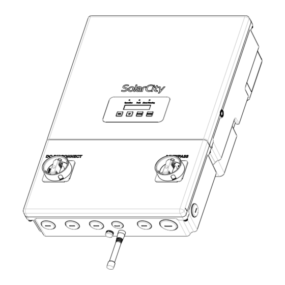
SolarCity H6 Installation & Operation Manual (146 pages)
Hybrid Inverter
Brand:
SolarCity
| Category:
Inverter
| Size: 4 MB
Table of Contents
Table of Contents
3
1 Welcome
11
Figure 1-1: Typical PV Installation with a Solarcity H6 Inverter
13
Figure 1-2: Block Diagram of a Complete Solarcity H6 Inverter Installation
14
Qualification of Skilled Workers
15
General H6 Features
15
Package Contents
16
Additional Tools
16
About this Manual
17
Formatting Conventions
17
Figure 1-3: Ratchet Wrench, Long-Shank Screwdriver, and Chip Puller
17
Safety Symbols
18
Layout
19
Related Documentation
20
Additional Resources
20
Technical Support
20
2 Safety Instructions
21
General
21
Solarcity H6 Inverter
22
Safety Labels
24
Figure 2-1: Solarcity H6 Safety Labels
24
Battery Pack Safety
25
3 Overview
27
Layout
27
Figure 3-1: Solarcity H6 Inverter with Callouts
27
Dimensions & Clearances
30
Inverter Dimensions
30
Figure 3-2: Solarcity H6 Inverter Dimensions (Front View)
30
Figure 3-3: Solarcity H6 Inverter Dimensions (Bottom View)
30
Clearances
31
Figure 3-4: Minimum Clearances (Below)
31
Inverter Mounting Bracket
32
Figure 3-5: Solarcity H6 Inverter Mounting Bracket with Hooks
32
Standard 16" Wall
33
Figure 3-6: Installing the Inverter Mounting Bracket on Various Wall Types
33
24" Wall
34
Single Pillar
34
Masonry or Concrete Walls
34
DC and AC Switches
35
DC Disconnect Switch
35
Figure 3-7: DC Disconnect Switch in on Position
35
Figure 3-8: DC Disconnect Switch in off Position
35
AC Bypass Switch
36
Figure 3-9: AC Bypass Switch in the INV Position
36
Figure 3-10: AC Bypass Switch in the BYP Position
36
Inverter Wiring Box
37
Figure 3-11: Solarcity H6 Inverter Wiring Box Connections
37
Figure 3-12: Wiring Box Label
37
PV Interface
38
Figure 3-13: Parallel String Connections
39
Figure 3-14: Fireman Switch Connections
40
Figure 3-15: Fireman Switch Operation (Below)
40
Figure 3-16: DC Disconnect Switch Operation (Below)
40
Battery Pack Interface
41
Communications
41
Figure 3-17: High-Voltage Battery Pack Connections
41
Backup/Protected Loads Panel
42
Figure 3-18: Communications Connections (Colors May Vary)
42
Figure 3-19: Backup Load Connections
43
AC Grid Point of Interconnection
44
Figure 3-20: AC Grid POI Output Connections
44
Whole-Home Backup at the Main Panel
45
Mechanical Interlock Kit on the Main Panel
45
Figure 3-21: Mechanical Interlock Kit (MIK) Installed on a Main Panel
45
Mechanical Interlock Kit on a Separate Manual Transfer Switch
46
Figure 3-22: Mechanical Interlock Kit (MIK) Installed on a Manual Transfer Switch (MTS)
46
Sources for MIK and MTS Products
47
External Components
47
PV Array
47
Battery Pack
48
Back-Up Electrical Panel
49
Main Electrical Panel
51
Fireman Switch and Rapid Shutdown
52
Components
52
System Diagram
53
Figure 3-23: RSS Components and Wiring
53
Fireman Switch Sequence
54
DC Disconnect Switch Sequence
55
4 Installation
57
Visual Inspection
58
Selecting a Location
58
Figure 4-1: Inverter Orientation
59
Mounting the Inverter
60
Installing the Inverter Mounting Bracket
61
Hanging the Inverter
62
Figure 4-2: Hanging the Solarcity H6 Inverter on the Mounting Bracket
63
5 Electrical Connections
65
System Wiring Diagrams
67
Figure 5-1: Solarcity H6 Installation Wiring Diagram (1 of 2)
67
Figure 5-2: Solarcity H6 Installation Wiring Diagram (2 of 2)
68
Wiring Box Cover
69
Remove Wiring Box Cover
69
Refit Wiring Box Cover
70
Figure 5-3: Removing the Wiring Box Cover and Close-Up of Screw Head
70
Conduit Plugs and Fittings
71
Figure 5-4: Rain-Tight Compression Connector
71
Grounding Connections
72
Using the Spring Clamp Connectors
72
PV Connections
73
Figure 5-5: Using the Spring Clamp Connectors
73
Limitations
74
Wiring
74
Battery Pack Connections
75
Wiring
75
Fuses
76
Communications
76
AC Voltage
77
Output to Grid
77
Utility Back-Feed (OCPD) Circuit Breaker
78
Output to Backup Load Center
78
Communications
79
Zigbee & Gateway
79
Integrated Revenue Grade Meter (RGM)
79
PV-Only Charging
79
Rapid Shutdown (RSD)
80
Dark-Start Feature
80
Fireman Switch
81
Figure 5-6: Fireman Switch
81
6 User Controls
83
Displays and Buttons
83
Figure 6-1: Solarcity H6 Inverter Leds, LCD Display, and Buttons
83
Figure 6-2: Interpreting the Solarcity H6 Inverter Leds
85
Status Leds
85
LCD Display
86
Push Buttons
86
Menu Structure
87
System Overview Menu
87
Current Status Menu
89
External Messages Menu
89
Software Versions Menu
89
Clear Fault Menu
90
Soft Shutdown Menu
90
Grid Settings Menu
90
Zigbee (Xbee) Information Menu
91
7 Commissioning
93
8 Basic Operation
95
Powering on the Inverter
95
Powering off the Inverter
96
Bypassing the Inverter
96
Opening/Closing the Inverter
96
Power Flow Modes
97
PV to Battery Pack
97
PV to AC Grid Output
97
PV to Protected Home Loads
97
Battery Pack to AC Grid Output
97
Battery Pack to Protected Home Loads
98
AC Grid to Protected Home Loads
98
AC Grid to Battery Pack
98
On-Grid to Off-Grid Status
99
Off-Grid to On-Grid Status
99
9 Product Information
101
Specifications
101
General
101
Mechanical
102
PV Input
102
AC Output
103
Battery Pack Interface
103
Protection Features
104
Arc Fault Circuit Interrupter
104
Anti-Islanding Protection
104
Reverse Polarity
104
Residual Current Detection (RCD)
104
Fireman Switch
104
RISO (PV Insulation Resistance Monitor)
105
Standards & Directives
105
Communication
105
Thermal, Voltage, and Efficiency Charts
106
Thermal De-Rating
106
Figure 9-1: Temperature De-Rating Graph
106
PV Voltage and AC Output Power
107
Figure 9-2: AC Output Power Vs. PV Input Voltage Range
107
PV Input Voltage and Efficiency
108
Figure 9-3: CEC Efficiency Vs. PV Input Voltage
108
Battery Pack Round-Trip (Charging & Discharging) Efficiency
109
Figure 9-4: Battery Pack Charging Efficiency
109
Figure 9-5: Battery Pack Discharging Efficiency
109
Regulatory Approvals
110
FCC Compliance
110
UL Certificate
111
10 Troubleshooting and Maintenance
113
Intended Uses
113
General Troubleshooting
113
Alarms, Faults, and Warnings
115
Alarms
115
Faults
116
Warnings
118
Replacing the Inverter
119
Inverter (Remove)
119
Inverter (Refit)
120
Figure 10-1: Removing the Solarcity H6 Inverter Top Section
120
Figure 10-2: Wires from Inverter Top Section to Wiring Box
122
Replacing Internal Components
123
Figure 10-3: Internal Components (with Separate PLC, Top; with Integrated PLC, Bottom)
123
Fuses
125
Fan
126
PLC Transmitter
126
Zigbee Chip
128
Figure 10-4: Zigbee Chip with Circuit Breaker Cover Removed
129
9-Volt Battery
130
Figure 10-5: 9-Volt Battery (Unit with Separate PLC, Top; with Integrated PLC, Bottom)
130
Warranty and Returns
131
A - Glossary
133
B - SMART Rapid Shutdown Slave
137
Dimensions and Clearances
138
SMART RSS Dimensions
138
Figure B-1: SMART RSS Dimensions
138
Clearances
139
Figure B-2: Minimum SMART RSD Clearances
139
Installing the SMART RSS
140
Figure B-3: Installing the SMART RSS (Below)
141
Removing the SMART RSS
142
Figure B-4: Removing the SMART RSS
142
Grounding the SMART RSS
143
Warning Label
143
Self-Test
143
Specifications
144
Mechanical
144
Ratings
144
Compliance
145
Advertisement
Advertisement
Related Products
SolarCity solarZero
SolarCity Categories
Inverter
Solar panel
Lifting Systems
More SolarCity Manuals
Login
Sign In
OR
Sign in with Facebook
Sign in with Google
Upload manual
Upload from disk
Upload from URL