Table of Contents
Advertisement
Advertisement
Table of Contents

Related Manuals for SolarCity H6

Summary of Contents for SolarCity H6
- Page 1 Hybrid Inverter Installation & Operation Guide...
- Page 2 Specifications are subject to change without notice. Every attempt has been made to make this document complete, accurate and up-to-date. Readers are cautioned, however, that SolarCity Corporation reserves the right to make changes without notice and shall not be responsible for any damages, including indirect, incidental or consequential damages, caused by reliance on the material presented, including, but not limited to, omissions, typographical errors, arithmetical errors or listing errors in the content material.
-
Page 3: Table Of Contents
1.8 - Technical Support ....................10 2 - Safety Instructions ................11 2.1 - General........................11 2.2 - SolarCity H6 Inverter....................12 2.3 - Safety Labels ......................14 2.4 - Battery Pack Safety ....................15 3 - Overview ..................17 3.1 - Layout ........................17... - Page 4 H6 Hybrid Inverter - Installation & Operation Guide 3.6 - Whole-Home Backup at the Main Panel ..............35 3.6.1 - Mechanical Interlock Kit on the Main Panel ............35 3.6.2 - Mechanical Interlock Kit on a Separate Manual Transfer Switch ....... 36 3.6.3 - Sources for MIK and MTS Products..............
- Page 5 9 - Product Information ................ 91 9.1 - Specifications ......................91 9.1.1 - General......................91 9.1.2 - Mechanical .....................92 9.1.3 - PV Input ......................92 9.1.4 - AC Output ......................93 9.1.5 - Battery Pack Interface ..................93 Copyright 2017 SolarCity Corporation. All rights reserved.
- Page 6 H6 Hybrid Inverter - Installation & Operation Guide 9.2 - Protection Features....................94 9.2.1 - Arc Fault Circuit Interrupter ................94 9.2.2 - Anti-Islanding Protection ................94 9.2.3 - Reverse Polarity.....................94 9.2.4 - Residual Current Detection (RCD) ..............94 9.2.5 - Fireman Switch....................94 9.2.6 - RISO (PV Insulation Resistance Monitor)............95 9.3 - Standards &...
- Page 7 B.4 - Grounding the SMART RSS..................133 B.5 - Warning Label ..................... 133 B.6 - Self-Test ......................133 B.7 - Specifications ...................... 134 B.7.1 - Mechanical ....................134 B.7.2 - Ratings ......................134 B.7.3 - Compliance ....................135 Copyright 2017 SolarCity Corporation. All rights reserved.
- Page 8 H6 Hybrid Inverter - Installation & Operation Guide This page intentionally left blank. viii Copyright 2017 SolarCity Corporation. All rights reserved.
- Page 9 List of Figures Figure 1-1: Typical PV installation with a SolarCity H6 inverter ..........3 Figure 1-2: Block diagram of a complete SolarCity H6 inverter installation ......4 Figure 1-3: Ratchet wrench, long-shank screwdriver, and chip puller......... 7 Figure 2-1: SolarCity H6 safety labels ................14 Figure 3-1: SolarCity H6 inverter with callouts ..............17...
- Page 10 H6 Hybrid Inverter - Installation & Operation Guide Figure 4-2: Hanging the SolarCity H6 inverter on the mounting bracket ......53 Figure 5-1: SolarCity H6 installation wiring diagram (1 of 2) ..........57 Figure 5-2: SolarCity H6 installation wiring diagram (2 of 2) ..........58 Figure 5-3: Removing the wiring box cover and close-up of screw head......60...
-
Page 11: Welcome
1 - Welcome This guide describes the safety, installation, commissioning, operation, troubleshooting and maintenance of the SolarCity H6 inverter. The inverter may or may not include a pre-installed Power Line Communication (PLC) Transmitter. WARNING: THIS MANUAL IS FOR USE BY QUALIFIED PERSONNEL ONLY. - Page 12 Please refer to the PV module documentation for detailed temperature dependency information. The SolarCity H6 inverter contains an internal automatic transfer relay that enables off-grid operation. Protected home loads (also called protected loads) are loads extended from an existing electrical panel and placed into a new electrical panel called the “backup panel.”...
-
Page 13: Figure 1-1: Typical Pv Installation With A Solarcity H6 Inverter
AC current for use by the protected home loads. • SolarCity H6 inverter (4): Converts DC current from the panels/battery pack into AC current for use by the protected home loads and charges the battery pack when there is enough PV energy available to do so. -
Page 14: Figure 1-2: Block Diagram Of A Complete Solarcity H6 Inverter Installation
Rapid shutdown (RSD) mechanism per NEC 2014 690.12 is achieved through two parts: One part is the PLC Transmitter that is located in the H6 inverter, and the other part is the RSD boxes that are installed under the PV modules within 10’ (3m) of the PV arrays (depending on the number of strings). -
Page 15: Qualification Of Skilled Workers
Chapter 1 - Welcome The SolarCity H6 inverter may be mounted either indoors or outdoors. Outdoor locations should avoid direct sunlight to help prevent thermal de-rating (temperature-induced reduction in power performance). WARNING: THE SOLARCITY H6 INVERTER IS NOT INTENDED OR DESIGNED TO SUPPLY ENERGY TO LIFE-SUSTAINING MEDICAL DEVICES. -
Page 16: Package Contents
• Over-the-air (OTA) status updates of all critical information. • Built-in battery pack compatibility checking. 1.3 - Package Contents The H6 inverter ships with one (1) each of the following items: • Inverter unit • I-shaped Inverter Mounting Bracket •... -
Page 17: About This Manual
Procedures that must be followed in a specific order appear in numbered steps: Perform this step first. Perform this step second. Interface elements such as document titles, fields, windows, tabs, buttons, commands, options, and icons appear in bold text. Copyright 2017 SolarCity Corporation. All rights reserved. -
Page 18: Safety Symbols
H6 Hybrid Inverter - Installation & Operation Guide Specific commands/values appear in standard Courier font. Sequences of commands appear in the order in which you should execute them and include horizontal or vertical spaces between commands. 1.5.2 - Safety Symbols... -
Page 19: Layout
• Chapter 8 – Basic Operation: Covers routine procedures, such as powering the SolarCity H6 inverter on and off and how power flows to and from the inverter under a variety of “Basic Operation” on page 85 operating conditions. See •... -
Page 20: Related Documentation
H6 Hybrid Inverter - Installation & Operation Guide 1.6 - Related Documentation The following additional documentation is available for your SolarCity H6 inverter: • H6 Datasheet • SMART RSS Datasheet • UL Certificate • RGM Certificate • FCC Certificate These documents are available on the SolarCity Intranet (Grid). -
Page 21: Safety Instructions
The following general safety instructions apply to all portions of the installation at all times: • This guide is an integral part of the SolarCity H6 inverter product. It contains important instructions that must be followed when commissioning and maintaining the inverter. -
Page 22: Solarcity H6 Inverter
In no event shall SolarCity be held liable for any damage caused by such changes. • Any use of the SolarCity H6 inverter other than that described in this guide does not qualify as appropriate. •... - Page 23 Chapter 1 - Welcome • The SolarCity H6 inverter may only be operated when it is technically faultless and in an operationally safe state. Check the inverter and all components for visible damage during unpacking and installation. Ensure that all external safety equipment is freely accessible and in good working order at all times.
-
Page 24: Safety Labels
H6 Hybrid Inverter - Installation & Operation Guide 2.3 - Safety Labels Figure 2-1 The SolarCity H6 inverter includes a safety and type labels, as shown in Without PLC (IN-102212-060): I/C 6.0-2TL2-450-NA2 EOE47020609 With PLC (IN-102210-060): INVERTER/CHARGER 6.0-2TL2-450-RS-NA2 EOE47020667 Figure 2-1: SolarCity H6 safety labels... -
Page 25: Battery Pack Safety
Chapter 1 - Welcome 2.4 - Battery Pack Safety The following safety instructions apply to the SolarCity H6 inverter at all times: SHOCK HAZARD: THE SAFETY INSTRUCTIONS IN THIS GUIDE ARE PROVIDED FOR GENERAL INFORMATIONAL PURPOSES ONLY. THEY ARE NOT INTENDED TO OVERRIDE OR SUBSTITUTE FOR THE SAFETY INSTRUCTIONS CONTAINED WITHIN THE BATTERY PACK DOCUMENTATION. - Page 26 H6 Hybrid Inverter - Installation & Operation Guide • Do not open, disturb, modify, or damage the battery pack. • The battery pack connection includes high-voltage conductors that may cause death or serious injury by electrocution. • Deep discharges and/or repeated charge-discharge cycles that exceed warranty regulations can prematurely degrade the battery pack capacity.
-
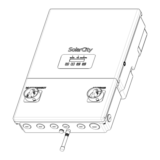
Page 27: Overview
3 - Overview This section introduces you to the SolarCity H6 inverter. 3.1 - Layout The SolarCity H6 inverter is laid out as follows: Figure 3-1: SolarCity H6 inverter with callouts Copyright 2017 SolarCity Corporation. All rights reserved. - Page 28 (3) M6 nuts. See for instructions on removing and refitting the top section. • Operation LED (2): This LED lights up green to indicate that the SolarCity H6 inverter is “Status LEDs” on page 75 functioning. See “Faults” on •...
- Page 29 AC Bypass Switch (12): By default, when set to the INV position, the AC Bypass Switch connects backup loads to the utility grid via the SolarCity H6 inverter; however, you can bypass the inverter and directly connect protected loads to the utility grid during service/maintenance by switching to the BYP position.
-
Page 30: Dimensions & Clearances
H6 Hybrid Inverter - Installation & Operation Guide 3.2 - Dimensions & Clearances This section displays the physical dimensions of the SolarCity H6 inverter and provides minimum clearance requirements. 3.2.1 - Inverter Dimensions Figure 3-2 Figure 3-3 display the physical dimensions of the SolarCity H6 inverter. -
Page 31: Clearances
(150mm) (150mm) >24" (610mm) Note: The SolarCity H6 inverter will go into power de-rating as described “Thermal De-rating” on page 96. If ambient temperate exceeds the maximum rating, the SolarCity H6 inverter will automatically shut off. CAUTION: THE SOLARCITY H6 INVERTER MAY OVERHEAT IF MOUNTED TOO CLOSE TO AN OVERHANGING ROOF AND/OR TOO CLOSE TO SURROUNDING ELECTRICAL EQUIPMENT. -
Page 32: Inverter Mounting Bracket
SolarCity H6 inverter on a standard wall with 16” stud spacing. • Top and bottom center holes for use when mounting the SolarCity H6 inverter to a wall with 24” stud spacing. Copyright 2017 SolarCity Corporation. All rights reserved. -
Page 33: Standard 16" Wall
Inverter Mounting Bracket are provided for additional bracket and inverter stability. The two top hooks slide into back of the SolarCity H6 inverter slots and hold most of the weight. The two bottom hooks slide into back of the wiring box slots and are useful when replacing the inverter top section because they hold the wiring box in place. -
Page 34: 24" Wall
H6 Hybrid Inverter - Installation & Operation Guide 3.3.2 - 24” Wall When installing the Inverter Mounting Bracket on a wall with 24” stud spacing: • Use one (1) in the upper middle into the stud. • Use one (1) screw in the lower middle into the stud. -
Page 35: Dc And Ac Switches
The DC Disconnect Switch turns DC power from the PV array and battery pack to the SolarCity H6 inverter ON or OFF. The DC Disconnect Switch includes a hole for a padlock to prevent inadvertently turning power ON or OFF. The DC Disconnect Switch must be set to OFF in order to remove the wiring box cover. -
Page 36: Ac Bypass Switch
3.4.2 - AC Bypass Switch The AC Bypass Switch connects home loads to the utility grid either: • Directly, when set to the BYP position (used when servicing/maintaining the SolarCity H6 inverter). • Via the SolarCity H6 inverter, when set to the INV position (default). -
Page 37: Inverter Wiring Box
Chapter 1 - Welcome 3.5 - Inverter Wiring Box Do not remove or disturb the connections between the SolarCity H6 inverter top section and the wiring box, except when replacing the inverter top section. All wiring must be performed only by qualified personnel. -
Page 38: Pv Interface
“AC Grid Point of Interconnection” on page 34 • AC Grid: See 3.5.1 - PV Interface The SolarCity H6 inverter can accommodate up to four (4) PV strings, as follows: • PV1A(+) and PV1A(-) = MPPT 1, String 1 •... -
Page 39: Figure 3-13: Parallel String Connections
Chapter 1 - Welcome The SolarCity H6 inverter does not use positive or negative grounding; however, a floating ground that connects the chassis of each component must be included in the installation. For example, each string or array may bring in both high-voltage lines and a ground wire that must be connected to the grounding bus inside the wiring box, as may the battery pack, main panel, etc. -
Page 40: Figure 3-14: Fireman Switch Connections
H6 Hybrid Inverter - Installation & Operation Guide The Rapid Shutdown Slaves (PLC receivers) that receive these PLC signals are embedded in the RSD boxes on the roof. An RSD signal initiates a rapid shutdown function when triggered by the Fireman Switch located either beside the main panel or by the DC Disconnect Switch. -
Page 41: Battery Pack Interface
Chapter 1 - Welcome 3.5.2 - Battery Pack Interface The SolarCity H6 inverter connects directly to the battery pack output via two high-voltage lines (BATT+ and BATT-). The battery pack is an un-grounded/floating system, meaning that there must also be a ground connection between the battery pack chassis and the inverter Figure 3-17 (bonding bushing not required). -
Page 42: Backup/Protected Loads Panel
The off-grid/standalone AC output to the protected home loads has two (2) high-voltage lines labeled BL1 and BL2, plus a neutral line labeled BN. The SolarCity H6 inverter includes a dedicated 3/4” conduit opening for the backup output connections on the bottom center,... -
Page 43: Figure 3-19: Backup Load Connections
Figure 3-19: Backup load connections Note: You may be able to route the backup panel and AC grid wiring together using the 1” conduit opening on the bottom right of the wiring box. Copyright 2017 SolarCity Corporation. All rights reserved. -
Page 44: Ac Grid Point Of Interconnection
H6 Hybrid Inverter - Installation & Operation Guide 3.5.5 - AC Grid Point of Interconnection The SolarCity H6 inverter output to the utility grid is a typical back-feed connection that connects the inverter to the public grid via the overcurrent protection (circuit breaker) located in the main electrical panel. -
Page 45: Whole-Home Backup At The Main Panel
This section provides an overview of systems for manually switching between the grid and the backup AC output of the SolarCity H6 inverter. A mechanical interlock kit (MIK) is placed on the main panel to ensure that only one of two circuit breakers can be in the ON position at the same time. -
Page 46: Mechanical Interlock Kit On A Separate Manual Transfer Switch
(MTS) is installed on the main breaker, and the MIK is then installed on the MTS, as shown in Figure 3-22 The MIK is installed on the MTS panel, allowing either the main MTS breaker or the H6 inverter standalone breaker to be switched ON, but never both. MTS PANEL... -
Page 47: Sources For Mik And Mts Products
4.5kW (up to 75% imbalance), with the rest on the other MPPT channel. The total power of the PV array can range up to 150% (9kW) of the SolarCity H6 inverter maximum AC rating of 6kW. -
Page 48: Battery Pack
TABLE 310.15(B)(16) AND RATED TO AT LEAST 194°F (90°). 3.7.2 - Battery Pack The SolarCity H6 inverter is designed for use with the Tesla Powerwall 2 battery only. WARNING: USE ONLY THE SPECIFIC MAKE AND MODEL OF BATTERY THAT IS SPECIFICALLY RATED FOR USE WITH THE SOLARCITY H6 INVERTER. -
Page 49: Back-Up Electrical Panel
“DC Disconnect Switch” on page 25 ) contained within the SolarCity H6 inverter disconnects both the PV array and the battery pack at the same time. In addition, some battery packs may have a separate disconnect switch that is either integrated into the battery pack or installed close to the battery pack externally. - Page 50 Note: In night mode, the SolarCity H6 inverter may take up to eight (8) seconds to transition from on-grid to off-grid. IEEE 1547 and ANSI regulations specify the following default operating ranges •...
-
Page 51: Main Electrical Panel
Chapter 1 - Welcome 3.7.4 - Main Electrical Panel The SolarCity H6 inverter can only be tied to the 240V, 60Hz North American split single- phase public grid. Configuration can be performed using either the built-in LCD display or a remote connection (see “Menu Structure”... -
Page 52: Fireman Switch And Rapid Shutdown
PLC Transmitter: This is a small box or PCB with integrated circuit that is installed inside the SolarCity H6 inverter Wiring Box. This box communicates with the RSS box(es) using signals sent via the PV power cables. This part is UL-listed as part of the inverter assembly. -
Page 53: System Diagram
Chapter 1 - Welcome 3.8.2 - System Diagram Figure 3-12 displays the RSS components and wiring. PV STRINGS PV STRINGS PLC TRANSMITTER MAX. 15M FROM INVERTER Figure 3-23: RSS components and wiring Copyright 2017 SolarCity Corporation. All rights reserved. -
Page 54: Fireman Switch Sequence
The PLC Transmitter stops PLC communications with the RSS box(es). The RSS box(es) disconnect the PV panels from the PV power cables. Any remaining voltage on the PV power cables between the RSS box(es) and the SolarCity H6 inverter will discharge below 30V within less than ten (10) seconds. -
Page 55: Dc Disconnect Switch Sequence
Personnel responding to an emergency must turn the DC Disconnect Switch in the SolarCity H6 inverter to the OFF position. If the Fireman Switch is not available and/or not used, then the then the rapid shutdown sequence proceeds as follows: The SolarCity H6 inverter detects the activation of the DC Disconnect Switch and: Illuminates the red LED. - Page 56 H6 Hybrid Inverter - Installation & Operation Guide Copyright 2017 SolarCity Corporation. All rights reserved.
-
Page 57: Installation
A LICENSED ELECTRICIAN IN ACCORDANCE WITH LOCAL, STATE, AND NATIONAL ELECTRICAL CODE ANSI/NFPA 70 REQUIREMENTS. WARNING: THE METHODS USED TO INSTALL AND WIRE THE SOLARCITY H6 INVERTER IN THE UNITED STATES MUST COMPLY WITH ALL US NATIONAL ELECTRIC CODE REQUIREMENTS (NEC) AND LOCAL AHJ INSPECTOR REQUIREMENTS. -
Page 58: Visual Inspection
“Package Contents” on page 6 listed in Visually inspect the SolarCity H6 inverter for any physical damage such as a bent heatsink fin and/or a dented chassis. If the inverter appears to be damaged or if the inverter needs to be returned, please contact your local SolarCity representative. -
Page 59: Figure 4-1: Inverter Orientation
Avoid exposure to water or heavy soiling, even though the inverter conforms to NEXA 4X and IP67 requirements. Choose a mounting height that allows easy viewing and access to the LED lights, LCD display, and buttons on the inverter while meeting all clearance requirements. Copyright 2017 SolarCity Corporation. All rights reserved. -
Page 60: Mounting The Inverter
LEGS AND FOLLOW ALL OTHER APPLICABLE BEST PRACTICES FOR AVOIDING INJURY WHEN LIFTING HEAVY LOADS. 4.3 - Mounting the Inverter Refer to the following instructions before installing the SolarCity H6 inverter: “Qualification of Skilled Workers” on page 5 • “Safety Instructions” on page 11 •... -
Page 61: Installing The Inverter Mounting Bracket
CAUTION: VERIFY THAT BOTH THE SHEAR AND PULL-OUT STRENGTH OF ALL SCREWS AND ANCHORS USED TO INSTALL THE INVERTER MOUNTING BRACKET ARE SUFFICIENT TO BEAR THE WEIGHT OF THE SOLARCITY H6 INVERTER. Note: Stainless steel screws are recommended, especially for outdoor locations. -
Page 62: Hanging The Inverter
Refer to the numbered callouts in . To hang the SolarCity H6 inverter: WARNING: THE SOLARCITY H6 INVERTER WEIGHS 62LBS (28KG). ALL LIFTING MUST BE PERFORMED BY TWO PEOPLE. ALWAYS LIFT WITH YOUR LEGS AND FOLLOW ALL OTHER APPLICABLE BEST PRACTICES FOR AVOIDING INJURY WHEN LIFTING HEAVY LOADS. -
Page 63: Figure 4-2: Hanging The Solarcity H6 Inverter On The Mounting Bracket
Chapter 1 - Welcome “Electrical Connections” on page 55 Wire the inverter as described in Figure 4-2: Hanging the SolarCity H6 inverter on the mounting bracket Copyright 2017 SolarCity Corporation. All rights reserved. - Page 64 H6 Hybrid Inverter - Installation & Operation Guide Copyright 2017 SolarCity Corporation. All rights reserved.
-
Page 65: Electrical Connections
5 - Electrical Connections This section provides instructions for making the electrical connections to the SolarCity H6 inverter. WARNING: READ ALL OF THESE INSTRUCTIONS, CAUTIONS, AND WARNINGS FOR THE H6 INVERTER AND ASSOCIATED PV ARRAY DOCUMENTATION. SHOCK HAZARD: POWER MAY BE FED FROM MORE THAN ONE SOURCE AND/OR VIA MORE THAN ONE LIVE CIRCUIT. - Page 66 H6 Hybrid Inverter - Installation & Operation Guide WARNING: THE APPROPRIATE LOCAL UTILITY MUST PROVIDE APPROVAL BEFORE CONNECTING THE SOLARCITY H6 INVERTER TO THE AC DISTRIBUTION GRID, AS REQUIRED BY NATIONAL AND STATE INTERCONNECTION REGULATIONS. THE INTERCONNECTION MUST BE PERFORMED BY QUALIFIED PERSONNEL.
-
Page 67: System Wiring Diagrams
SolarCity H6 inverter installation. MODULE FRAME GROUND ¾” CONDUIT ¾” CONDUIT MODULE FRAME GROUND ¾” CONDUIT SEE FIGURE 5-2 Figure 5-1: SolarCity H6 installation wiring diagram (1 of 2) Copyright 2017 SolarCity Corporation. All rights reserved. -
Page 68: Figure 5-2: Solarcity H6 Installation Wiring Diagram (2 Of 2)
H6 Hybrid Inverter - Installation & Operation Guide SEE FIGURE 5-1 Figure 5-2: SolarCity H6 installation wiring diagram (2 of 2) Copyright 2017 SolarCity Corporation. All rights reserved. -
Page 69: Wiring Box Cover
5.2.1 - Remove Wiring Box Cover To remove the wiring box cover from the SolarCity H6 inverter: If the SolarCity H6 inverter is already installed and operating, then power it OFF as described in “Powering Off the Inverter” on page 86 Place the DC Disconnect Switch in the OFF position. -
Page 70: Refit Wiring Box Cover
Figure 5-3: Removing the wiring box cover and close-up of screw head 5.2.2 - Refit Wiring Box Cover To replace the wiring box cover on the SolarCity H6 inverter: Place the cover in position against the inverter, making sure that the DC Disconnect Switch is in the OFF position. -
Page 71: Conduit Plugs And Fittings
If you are installing the inverter, then continue with the installation/connections “Conduit Plugs and Fittings” on page 61 beginning with If the SolarCity H6 inverter is already installed and operating, then power it ON as “Powering On the Inverter” on page 85 described in 5.3 - Conduit Plugs and Fittings... -
Page 72: Grounding Connections
Main electrical panel • Backup electrical panel The SolarCity H6 inverter is designed and certified to meet the lightning and surge requirements contained in UL 1741, IEEE 1547, and ANSI/ IEEE 62.41/62.42 AC. WARNING: THE SOLARCITY INPUT AND OUTPUT CONNECTIONS ARE ELECTRICALLY ISOLATED FROM THE ENCLOSURE. -
Page 73: Pv Connections
ARE UNGROUNDED BUT WILL BECOME INTERMITTENTLY GROUNDED WITHOUT INDICATION WHEN THE INVERTER MEASURES THE PV ARRAY ISOLATION. SHOCK HAZARD: RISK OF ELECTRIC SHOCK AND FIRE. USE ONLY WITH PV MODULES WITH A MAXIMUM SYSTEM VOLTAGE OF 570V OR LOWER. Copyright 2017 SolarCity Corporation. All rights reserved. -
Page 74: Limitations
5.6.2 - Wiring To connect the PV array wires to the SolarCity H6 inverter: Connect one 3/4” conduit to the SolarCity H6 inverter for each MPPT channel (up to two “Conduit Plugs and channels supported) using watertight conduit fittings, as described in Fittings”... -
Page 75: Battery Pack Connections
5.7.1 - Wiring To connect the high-voltage battery pack wiring to the SolarCityH6 inverter: Run and connect one 3/4” conduit to the SolarCity H6 inverter for the combined battery pack voltage and communications wires using a watertight conduit fitting, as described in “Conduit Plugs and Fittings”... -
Page 76: Fuses
Note: Actual wiring colors may vary from those shown on the wiring box label and/or this Guide. 5.7.2 - Fuses The SolarCity H6 inverter accepts a maximum battery pack fuse rating of 25A. CAUTION: LARGER FUSES WILL VOID THE WARRANTY. CAUTION: FUSES THAT ARE TOO FAST MAY OPEN TOO EARLY AND INTERRUPT NORMAL OPERATION. -
Page 77: Ac Voltage
Do not use fine-stranded wire. To connect the AC grid wiring to the SolarCityH6 inverter: Run and connect one (1) 1” conduit to the SolarCity H6 inverter for the AC output wires to the main panel using a watertight conduit fitting, as described in “Conduit Plugs and... -
Page 78: Utility Back-Feed (Ocpd) Circuit Breaker
A dedicated back-feed circuit breaker must be installed in the main electrical panel for each SolarCity H6 inverter in the installation. Each L1 and L2 AC line must have a circuit breaker or disconnect in order to isolate the AC grid connection when needed. The circuit breaker must be rated for the maximum output voltage and current of the inverter. -
Page 79: Communications
ZigBee to the SolarCity server. This precision is revenue-grade ANSI C12.1, 1% class. 5.9.3 - PV-Only Charging The SolarCity H6 inverter is primarily intended to act as a PV inverter that also provides backup power to protected home loads. Utility restrictions prevent the inverter from using grid power to charge the battery pack, meaning that all battery pack power must come from the PV array and that the battery pack can only discharge to the protected home loads. -
Page 80: Rapid Shutdown (Rsd)
SMART RSD device and the SolarCity H6 inverter becomes de-energized below 30V, 8A, 240VA within less than ten (10) seconds. The SolarCity H6 inverter will not export AC power to the grid or to protected home loads and also disables the battery pack at “Fireman Switch and Rapid Shutdown”... -
Page 81: Fireman Switch
To use the Fireman Switch: Push the red button. This holds the button close to the housing and sends a signal to the SolarCity H6 inverter, which in turn sends a wireless PLC signal through the PV array lines to the RSD boxes on the roof, which respond by isolating the PV array from the rest of the system. - Page 82 H6 Hybrid Inverter - Installation & Operation Guide Copyright 2017 SolarCity Corporation. All rights reserved.
-
Page 83: User Controls
Figure 6-1: SolarCity H6 inverter LEDs, LCD display, and buttons Figure 6-1 The numbered callouts in correspond to the following: • Operation LED (1): This LED lights up green to indicate that the SolarCity H6 inverter is “Status LEDs” on page 75 functioning. See “Status LEDs” on •... - Page 84 H6 Hybrid Inverter - Installation & Operation Guide • Alarm/Warning LED (3): This LED lights up amber when an alarm or warning condition “Status LEDs” on page 75 “Alarms” on page 105 “Warnings” on page 108 occurs. See , and •...
-
Page 85: Status Leds
Chapter 1 - Welcome 6.1.1 - Status LEDs Figure 6-1 As shown in , the SolarCity H6 inverter includes the following three LEDs: Label Designation Color Operation Operation Green Fault Error Alarm/Warning Warning Yellow The LEDs will either remain off, illuminate steadily, or blink to indicate various system Figure 6-2 statuses. -
Page 86: Lcd Display
H6 Hybrid Inverter - Installation & Operation Guide 6.1.2 - LCD Display Figure 6-1 As shown in , the SolarCity H6 inverter includes a two (2) line LCD display with 16 characters per line. In this display: • The first row names the currently-displayed menu. -
Page 87: Menu Structure
This automatic scrolling menu can be paused and resumed by pressing the ENTER button. It displays the following system metrics and information: • Runtime: Number of hours of operation since the SolarCity H6 inverter was first powered • Active power: Watts •... - Page 88 Time: Current time received from the SolarCity server and adjusted for geographical location). • Type: Inverter type. • SN: Serial number of the SolarCity H6 inverter, as displayed on the name plate ratings label. Copyright 2017 SolarCity Corporation. All rights reserved.
-
Page 89: Current Status Menu
Battery Fault: There is a fault within the Battery Pack. 6.2.3 - External Messages Menu This menu displays up to four (4) text messages sent from SolarCity to the inverter via the wireless ZigBee connection. Each message can contain up to 16 characters. -
Page 90: Clear Fault Menu
Clear Other: Clear other faults. 6.2.6 - Soft Shutdown Menu This menu allows you to shutdown the SolarCity H6 inverter. You may select either Yes to proceed with the soft shutdown or No to cancel. 6.2.7 - Grid Settings Menu This menu displays the following grid settings: •... -
Page 91: Zigbee (Xbee) Information Menu
• Store and accept: Select either Yes or No. Note: Grid settings are password protected. Contact Technical Support or the SolarCity Hotline for this information. Utility approval may be required to adjust these settings. 6.2.8 - ZigBee (Xbee) Information Menu This menu displays the following information about ZigBee communications: •... - Page 92 H6 Hybrid Inverter - Installation & Operation Guide This page intentionally left blank. Copyright 2017 SolarCity Corporation. All rights reserved.
-
Page 93: Commissioning
81 If the SolarCity H6 inverter detects an AC overload during off-grid operation, it will attempt to restart up to three times and will then display an alarm message notifying you to remove/ shed some of the loads that may have caused the overload. Resolve the issue and then press any button to restore normal operation. - Page 94 H6 Hybrid Inverter - Installation & Operation Guide This page intentionally left blank. Copyright 2017 SolarCity Corporation. All rights reserved.
-
Page 95: Basic Operation
Move the breaker(s) in the backup load panel to the ON (closed) position. “Commissioning” on page 83 Follow the directions in to complete the setup process that will allow the SolarCity H6 inverter to begin feeding power to the grid and/or charging the battery pack. Copyright 2017 SolarCity Corporation. All rights reserved. -
Page 96: Powering Off The Inverter
LEAD TO DEATH OR SERIOUS INJURY FROM ELECTROCUTION. 8.3 - Bypassing the Inverter If the SolarCity H6 inverter is damaged and is not functioning, then the AC Bypass Switch can be turned to the BYP position. This will directly connect the protected home loads to the AC grid, bypassing the inverter. -
Page 97: Power Flow Modes
Chapter 1 - Welcome 8.5 - Power Flow Modes The SolarCity H6 inverter operates in several power modes, as described in the following sections. 8.5.1 - PV to Battery Pack This is a factory-default mode that the inverter can automatically select when appropriate. If the inverter is receiving power from both the grid and PV array, then it will use that PV energy to charge the battery pack first. -
Page 98: Battery Pack To Protected Home Loads
H6 Hybrid Inverter - Installation & Operation Guide communication with the SolarCity server, then it will revert to automatic modes and cancel this mode. Note: This mode is only available when approved by the local utility and can be enabled or disabled via software remotely in the SolarCity H6 inverter. -
Page 99: On-Grid To Off-Grid Status
OUTAGE MIGHT LEAD TO DEATH OR PERSONAL INJURY. 8.5.9 - Off-Grid to On-Grid Status During off-grid operation, if the grid voltage comes back, then the SolarCity H6 inverter will continue to operate using available PV and/or battery pack power while it performs a smooth transition to on-grid operation;... - Page 100 H6 Hybrid Inverter - Installation & Operation Guide This page intentionally left blank. Copyright 2017 SolarCity Corporation. All rights reserved.
-
Page 101: Product Information
SolarCity H6 inverter. 9.1 - Specifications This section lists the specifications of the SolarCity H6 inverter. Note: These values are subject to change. Please refer to the SolarCity H6 Inverter Datasheet for updated values. 9.1.1 - General The general specifications of the SolarCity H6 inverter are: •... -
Page 102: Mechanical
Display: Three (3) LEDs, two (2)-line LCD with 16 characters per line • Enclosure Material: Die-cast aluminum • Revenue Grade Meter: ANSI C12.1, 1% Class 9.1.3 - PV Input The PV input specifications of the SolarCity H6 inverter are: • Nominal Voltage: 380V • Max. System Voltage: 570V •... -
Page 103: Ac Output
Off-Grid Transition Time: <2 seconds • Conduit and Wire Size: Two (2) 3/4” conduit; 8-10AWG 9.1.5 - Battery Pack Interface The battery pack interface specifications of the SolarCity H6 inverter are: • Operating Battery Pack Voltage Range: 430-550V • Max. Battery Pack Voltage @ Interface: 570V •... -
Page 104: Protection Features
UL1699B. Once triggered, the AFCI must be reset manually by selecting Clear Fault>Clear Arc Fault on the inverter. 9.2.2 - Anti-Islanding Protection The SolarCity H6 inverter includes an active safety algorithm that protects against islanding, per IEEE 1547 and UL 1741. 9.2.3 - Reverse Polarity Reversing the PV input positive (+) and negative (-) connections causes the inverter to either conduct maximum current at 0V or incur damage. -
Page 105: Riso (Pv Insulation Resistance Monitor)
Chapter 1 - Welcome 9.2.6 - RISO (PV Insulation Resistance Monitor) Per NEC, every morning (24 hours) or upon restarting, the SolarCity H6 inverter checks the PV impedance to verify that it exceeds the threshold set by UL 1741. This check can also detect a ground fault situation. -
Page 106: Thermal, Voltage, And Efficiency Charts
This section contains charts that depict thermal de-rating, voltage vs. power, and 3D efficiency characteristics of the SolarCity H6 inverter. 9.5.1 - Thermal De-rating The SolarCity H6 inverter can be operated in ambient temperatures ranging from -20°C to Figure 9-1 60°C (-4°F to 140°F); however, power de-rating occurs above 45°C (113°F). -
Page 107: Pv Voltage And Ac Output Power
Chapter 1 - Welcome Note: SolarCity H6 inverter thermal de-rating may also be affected by thermal de-rating of the battery pack. Please see the thermal guidelines for the battery pack. 9.5.2 - PV Voltage and AC Output Power “AC Output power vs. PV input voltage range” on page 97 displays how changes in PV input voltage affect AC power output based on current input limitations. -
Page 108: Pv Input Voltage And Efficiency
H6 Hybrid Inverter - Installation & Operation Guide 9.5.3 - PV Input Voltage and Efficiency The SolarCity H6 inverter achieves maximum efficiency at PV input voltages ranges between Figure 9-3 380VDC and 420VDC, as shown in 97.25% 97.00% 96.75% 96.50% 96.25%... -
Page 109: Battery Pack Round-Trip (Charging & Discharging) Efficiency
9.5.4 - Battery Pack Round-Trip (Charging & Discharging) Efficiency The battery pack manufacturer provides the round-trip efficiency related to battery pack output; however, the SolarCity H6 inverter includes electronics that contribute to RF efficiency, as shown in Figure 9-4 Figure 9-5 E ciency - 200V PV to DC Charge Direc on 100.00... -
Page 110: Regulatory Approvals
CSA C22.2 - 107.1-01 • ASTM 4169-09 9.6.1 - FCC Compliance The SolarCity H6 inverter complies with Part 15, Subclass B of the FCC Rules. Operation is subject to the following conditions: • This device may not cause harmful interference, and •... -
Page 111: Ul Certificate
Chapter 1 - Welcome 9.6.2 - UL Certificate Copyright 2017 SolarCity Corporation. All rights reserved. - Page 112 H6 Hybrid Inverter - Installation & Operation Guide Copyright 2017 SolarCity Corporation. All rights reserved.
-
Page 113: Troubleshooting And Maintenance
10.1 - Intended Uses The SolarCity H6 inverter operates as a typical PV inverter and is also used to operate (charge/discharge) a battery pack. It can serve many common applications such as back-up, peak shaving, load sharing, demand response, and economic energy dispatch. It can also operate in off-grid mode for longer times as needed. - Page 114 Contact Delta Customer Service for further assistance as described in Support” on page 10 . Please be prepared to provide all pertinent information, including the model and serial number of the SolarCity H6 inverter. Copyright 2017 SolarCity Corporation. All rights reserved.
-
Page 115: Alarms, Faults, And Warnings
Chapter 1 - Welcome 10.3 - Alarms, Faults, and Warnings This section lists the SolarCity H6 inverter alarms, faults, and warnings along with their causes and solutions. 10.3.1 - Alarms The SolarCity H6 inverter can display the following alarms, which can be corrected as... -
Page 116: Faults
Switch. per second range. 10.3.2 - Faults The SolarCity H6 inverter can display the following faults, which can be corrected as described below: Display Cause Solution Red LED on AC overload AC overload in off-... - Page 117 Red LED on System fault in Digital IO plausibility inverter fail. Red LED on Error system Arc Fault Self Test. initialization Red LED on Error system Inverter relay test initialization failure. Copyright 2017 SolarCity Corporation. All rights reserved.
-
Page 118: Warnings
Cause Solution Red LED on Error system RCD self-test failure. N/A initialization 10.3.3 - Warnings The SolarCity H6 inverter can display the following warnings, which can be corrected as described below: Display Cause Solution Green LED Night mode (PV blinking once power not available). -
Page 119: Replacing The Inverter
Using a 10mm wrench, remove the three nuts (2) holding the top section of the inverter to the wiring box section. Position one person on either side of the SolarCity H6 inverter and lift it straight up and off the mounting tabs. -
Page 120: Inverter (Refit)
If you are not immediately replacing the top section with a new one, then replace the wiring box cover as described in “Refit Wiring Box Cover” on page 60 Figure 10-1: Removing the SolarCity H6 inverter top section 10.4.2 - Inverter (Refit) To refit the SolarCity H6 inverter top section: Ensure that the DC Disconnect Switch is in the OFF position. - Page 121 Chapter 1 - Welcome Position one person on either side of the SolarCity H6 inverter top section and lift it straight up until it is flush against the mounting bracket and can be lowered into position. WARNING: THE SOLARCITY H6 INVERTER WEIGHS 62LBS (28KG). ALL LIFTING MUST BE PERFORMED BY TWO PEOPLE, PER OSHA REQUIREMENTS.
-
Page 122: Figure 10-2: Wires From Inverter Top Section To Wiring Box
H6 Hybrid Inverter - Installation & Operation Guide “Refit Wiring Box Cover” on page 60 Replace the wiring box cover as described in “Powering On the Inverter” on page 85 Power on the inverter as described in RIBBON CABLE Figure 10-2: Wires from inverter top section to wiring box... -
Page 123: Replacing Internal Components
SolarCity H6 inverter wiring box. displays these components for units that have a separate PLC Transmitter box and for units with an integrated PLC Transmitter. Figure 10-3: Internal components (with separate PLC, top; with integrated PLC, bottom) Copyright 2017 SolarCity Corporation. All rights reserved. - Page 124 Fuse cover (1): Each of the two fuses is protected by a fuse cover. For clarity, only one of the two fuse covers is shown. “Fuses” on page 66 • Fuses (2): The SolarCity H6 inverter uses two fuses. See for the correct type of fuses to use. •...
-
Page 125: Fuses
Chapter 1 - Welcome 10.5.1 - Fuses The SolarCity H6 inverter includes two (2) fuses inside the wiring box for the high-voltage battery pack connections. Prompt replacement of damaged or broken fuses is critical to restore battery pack operation. To replace the fuses: Turn the DC Disconnect Switch to the OFF position. -
Page 126: Fan
Verify that the SolarCity H6 inverter and battery pack are functioning normally. 10.5.3 - PLC Transmitter The SolarCity H6 inverter may include a separate PLC Transmitter box (as shown below) or a PLC Transmitter that is integrated in the inverter. The PLC Transmitter sends shutdown commands to the Remote Shutdown Slaves (RSS) when the Fireman Switch is activated. - Page 127 Disconnect the data cable from the connector (1). Disconnect the DC wires from the spring clamp connectors (2). Remove the two M3 hex nuts (3), and then lift the PLC Transmitter out of the SolarCity H6 inverter. Place the PLC Transmitter into position over the two threaded studs, and then secure the PLC Transmitter using two (2) M3 hex nuts (3).
-
Page 128: Zigbee Chip
Verify that the SolarCity H6 inverter and battery pack are functioning normally. 10.5.4 - ZigBee Chip The ZigBee chip may need replacing if communication between the SolarCity H6 inverter and the SolarCity server fails. To replace the ZigBee chip: Turn the DC Disconnect Switch to the OFF position. If the battery pack includes a DC disconnect, then turn that switch OFF as well. -
Page 129: Figure 10-4: Zigbee Chip With Circuit Breaker Cover Removed
If needed, configure the network for the MAC address of the new ZigBee chip. Verify that the ZigBee chip is communicating properly with the SolarCity server. Verify that the SolarCity H6 inverter and battery pack are functioning normally. Figure 10-4: ZigBee chip with circuit breaker cover removed... -
Page 130: 9-Volt Battery
H6 Hybrid Inverter - Installation & Operation Guide 10.5.5 - 9-Volt Battery To replace the 9-Volt Battery: Turn the DC Disconnect Switch to the OFF position. If the battery pack includes a DC disconnect, then turn that switch OFF as well. -
Page 131: Warranty And Returns
Chapter 1 - Welcome 10.6 - Warranty and Returns The standard warranty for the SolarCity H6 inverter is ten (10) years. This warranty can be extended to fifteen (15) or twenty (20) years. For assistance with warranty repairs or returns you may contact our North America support hotline at 1-877-442-4832 or via email at inverter.support@deltaww.com... - Page 132 H6 Hybrid Inverter - Installation & Operation Guide Copyright 2017 SolarCity Corporation. All rights reserved.
-
Page 133: A - Glossary
• CAN: Controller Area Network; communications standard that allows communication between microcontrollers and other devices without the need for a host computer. • CEC: Abbreviation for the California Energy Commission. Copyright 2017 SolarCity Corporation. All rights reserved. - Page 134 • Firmware: Firmware is software that is stored in a processor in various electronic devices, such as H6. Firmware is stored in Flash memory or an EEPROM chip. • Floating system: If the main electrical connections are not grounded in the system then it is considered as floating.
- Page 135 PV Array: Technical device for the conversion of solar energy into electrical energy. All electrically connected (in series and in parallel) PV modules of a PV system are referred to as the PV array. Copyright 2017 SolarCity Corporation. All rights reserved.
- Page 136 H6 Hybrid Inverter - Installation & Operation Guide • PV System: Describes the totality of devices required for the exploitation and utilization of solar energy. Sometimes, it includes not only the PV array, but also the SolarCity H6 inverter. •...
-
Page 137: B - Smart Rapid Shutdown Slave
NEC 2014 Article 690.12 when installed according to these instructions. The SMART RSS is compatible with the SolarCity H6 inverter. The SMART RSS may be mounted either to the top of a standard mounting rail beneath a PV module or indoors. -
Page 138: Dimensions And Clearances
H6 Hybrid Inverter - Installation & Operation Guide B.1 - Dimensions and Clearances This section displays the physical dimensions of the SMART RSS and provides minimum clearance requirements. B.1.1 - SMART RSS Dimensions Figure B-1 displays the physical dimensions of the SMART RSS. It also displays the input cables, output cables, SMART RSS box, and mounting bracket. -
Page 139: Clearances
Between bottom of PV module surface and top of SMART RSS: 0.6” (15mm) • Between roof surface and bottom of SMART RSS: 0.6” (15mm) • Between roof surface and back of PV module laminate: 2.6” (66mm)) Figure B-2: Minimum SMART RSD clearances Copyright 2017 SolarCity Corporation. All rights reserved. -
Page 140: Installing The Smart Rss
H6 Hybrid Inverter - Installation & Operation Guide B.2 - Installing the SMART RSS SHOCK HAZARD: BOTH THE POSITIVE AND THE NEGATIVE LEADS MUST BE STRICTLY ISOLATED ELECTRICALLY FROM BOTH GROUND AND EACH OTHER IN ORDER TO ENSURE MAXIMUM PROTECTION AGAINST HAZARDOUS VOLTAGES DURING SYSTEM ASSEMBLY. -
Page 141: Figure B-3: Installing The Smart Rss (Below)
Appendix B - SMART RSD Route the DC output conductors from the SMART RSS to the SolarCity H6 inverter PV “PV Interface” on page 28 “PV Array” on page 37 interface connections as described in ,and “PV Connections” on page 63 .If the SMART RSS is installed under the module or on racking,... -
Page 142: Removing The Smart Rss
H6 Hybrid Inverter - Installation & Operation Guide B.3 - Removing the SMART RSS To remove the SMART RSS: Use a screwdriver to unlock the tooth of the bracket. Lift the RSS and pull it out. Figure B-4: Removing the SMART RSS CAUTION: BE CAREFUL TO AVOID BENDING THE SMART RSS BRACKET. -
Page 143: Grounding The Smart Rss
Failure of the self-test will initiate a continuous alarm, and the SMART RSS will continue conducting the self-test until successfully completed. Devices that fail to complete their self-test must be replaced by a qualified service technician. Copyright 2017 SolarCity Corporation. All rights reserved. -
Page 144: Specifications
H6 Hybrid Inverter - Installation & Operation Guide B.7 - Specifications This section presents the specifications of the SMART RSS. B.7.1 - Mechanical The mechanical specifications of the SMART RSS are: • Height: 200mm (7.87”) • Width: 150mm (5.91”) •... -
Page 145: Compliance
Safety: UL 1741, UL 1741 CRD PVRSS, CSA-C22.2 No. 107.1-01 • Rapid shutdown: NEC 2014 Article 690.12 • EMC: FCC Part 15 B Note: These values are subject to change. Please refer to the SMART RSS Datasheet for updated values. Copyright 2017 SolarCity Corporation. All rights reserved. - Page 146 Hybrid Inverter Installation & Operation Guide SolarCity Corporation 3055 Clearview Way San Mateo, CA 94402 phone: (650) 638-1028 fax: (650) 560-6460 www.solarcity.com Version 1.1 (02/2017) PREVIOUS VERSIONS OBSOLETE...
Need help?
Do you have a question about the H6 and is the answer not in the manual?
Questions and answers
Can it be installed with a power wall battery?