Sign In
Upload
Manuals
Brands
Smiths Manuals
Water Pump
Graseby 3200
Smiths Graseby 3200 Manuals
Manuals and User Guides for Smiths Graseby 3200. We have
1
Smiths Graseby 3200 manual available for free PDF download: Technical & Service Manual
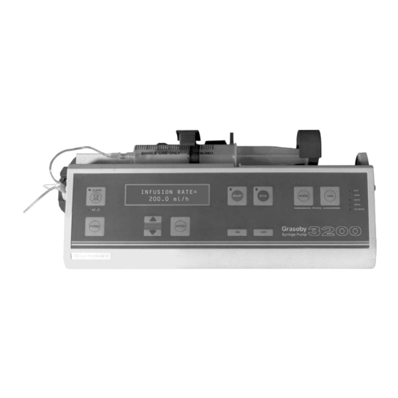
Smiths Graseby 3200 Technical & Service Manual (117 pages)
In-line Pressure Syringe Pump
Brand:
Smiths
| Category:
Water Pump
| Size: 0 MB
Table of Contents
Copyright and Address
2
Table of Contents
4
Warnings and Cautions
11
Abbreviations Used
14
Introduction, Features and Specification
15
Introduction
16
Security Cover
16
Features
18
Micro-Controller
18
AC Power Supply
19
Battery Life
19
Battery Type
19
DC Input Operation
19
Infusion Rates and Increments
19
Mass Unit Programming Range
19
Specification
19
Syringe Brands and Sizes
19
Volume Infused Counter
19
Dimensions
20
Display Languages Available
20
Drive Accuracy
20
Electrical Safety
20
Factory Set Occlusion
20
History
20
In-Line Occlusion Pressure Range
20
Internally Adjustable Occlusion Pressure
20
Temperature Range
20
Weight
20
CONFIGURATION, DIAGNOSTICS and OCCLUSION THRUST
22
Configuration Mode
23
Introduction
23
Changing a Setting
24
Entry into the Configuration Mode
24
Moving to the Next Parameter
24
Available Configuration Mode Parameters and Settings
25
Lock Progam Values
25
Max Infusion Rate
25
Syringe Brands 1
25
Syringe Size
25
Allow Mass Units Option
26
Infusion Units
26
KVO Rate
26
Preset Volume Mode with Time
26
Select Pump Modes
26
Show Rate in Ml/H While Infusing
26
Allow Bolus While Running
27
Allow Rate Change While Running
27
Display Pressure Bar Graph
27
Intermittent Mode Start Delay
27
RS232 Baud Rate
27
Use Pressure Transducer
27
Communication Mode
28
End of Menu
28
Pressure Units 25
28
Pump ID
28
Set Key Beep Volume
28
Diagnostic Mode
29
Entry into the Diagnostic Mode
29
Introduction
29
Moving to the Next Display
29
Calibrate Transducer
30
Diagnostic Displays
30
Software
30
Battery Voltage
31
Hours of Use 7
31
Language
31
Number of Faults
31
Transducer Alarm
31
Volume Infused
31
Entering the Clock Display
32
Setting the Clock
32
Assembly
33
Disassembly and Assembly of Casing
33
Taking the Casing Apart
33
Occlusion Measurements
34
Syringe Stiction
34
Thrust Measurements
34
Thrust Checks
35
Thrust Adjustments
36
Functional Descriptions
37
Drive System
38
Introduction
38
Microcomputer
38
Stepper Motor and Leadscrew
38
Toggle Mechanism
38
In-Line Occlusion System
39
Internal Occlusion System
39
Plunger Clamp
39
AC Power Failure
40
Electro/Mech Control System
40
End of Infusion
40
Introduction
40
Sensing (Alarm) Systems
40
Syringe Nearly Empty
40
Battery Voltage Low
41
Drive Disengaged or Syringe Not Fitted
41
Rate Setting
41
Self Tests/Pump Malfunction
41
Syringe Sizing System
41
Cannot Calibrate Extension Set
42
Cannot Zero Extension Set
42
Communications (RS232) Failure
42
Design
42
Self Tests
42
Software
42
Circuit Descriptions
43
Introduction
44
Main Board
44
Processor Core
45
Motor Interface
46
Power Control
46
Sensors Interface
47
RS232 D Connector
48
RS232 Serial Interface
48
Umbilical Connector
48
Input/Output Serial Interface
49
PL 11 Output
50
PL11 Connections
50
Setting RV1
51
Temperature/Voltage Range for Setting RV
51
D' Connector
52
Distribution Board
52
Main Board Components
52
Membrane Switch Panel
52
Pressure Sensing Board
52
Regulator Board Components
52
Status Sensors
52
Syringe Size Sensors
52
Fault Codes
71
FAULT CODES, CLEANING, RENEWAL of FUSES and REPAIRS
71
Main Processor Fault Codes
71
Access to Fuses
74
Cleaning
74
Renewal of Fuses
74
Repairs
74
Main Board Renewal
75
Regulator Board Renewal
75
Status Sensors Board Renewal
75
Leadscrew Assembly Renewal
76
Plunger Clamp and Super Nut Assembly Renewal
76
Pole Clamp Assembly Renewal
76
Motor and Gearbox Assembly Renewal
77
Occlusion Clutch and Disc Assembly Renewal
77
Membrane Switch Panel Renewal
78
Super Nut Renewal
78
ACAM Pressure Sensing Assembly Renewal
79
Plunger Clamp Repair
79
Syringe Size Sensors Assembly Renewal
79
Batteries. Checks and Replacement
80
Checks
80
Front And/Or Rear Case Repairs
80
Replacement
80
Front Case Spares Kit
81
Size Sensor Flag Spares Kit
81
Rear Case Spares Kit
82
Functional Tests
83
Plunger Clamp Alarm Checks
87
Ramp Check Procedures
87
Linear Accuracy
88
Plunger Clamp Alignment
88
Test Procedures
88
Manufacturing Settings
89
Illustrated Parts Lists
92
Leadscrew Assembly
93
Regulator Board Assembly - AC Power
104
Braun Perfusor Conversion
105
Braun Perfusor Selection
106
Introduction
106
Nearly Empty Flag Conversion
106
P' Label Fitment
106
Plunger Clamp Fitment Plate
106
Spacer Tube Fitment
106
Syringe Conversion Procedures
106
Mechanical Procedures
107
Programming Procedures
107
Reselecting 'Various' Syringe Brands
107
DC INPUT VERSION of 3200
108
Introduction
109
Appendix
111
FITTING a MODIFIED SIZE SENSOR FLAG
112
Introduction
112
Opening the Case
113
Removal of Old SSF
113
Reassembly
114
Setting the Size Sensor Flag
115
Advertisement
Advertisement
Related Products
Smiths Kelvin Hughes Nucleus 3 Series
Smiths Kelvin Hughes Nucleus 3 6000 Series
Smiths Kelvin Hughes Nucleus 3 5000 Series
Smiths Graseby MR10
Smiths Graseby MS16A
Smiths Graseby 500
Smiths Graseby Micro 505
Smiths Categories
Heater
Food Warmer
Cables and connectors
Medical Equipment
Measuring Instruments
More Smiths Manuals
Login
Sign In
OR
Sign in with Facebook
Sign in with Google
Upload manual
Upload from disk
Upload from URL