
Summary of Contents for Smiths Graseby 3200
- Page 1 Graseby 3200 In-line Pressure Syringe Pump INFUSION RATE= 200.0 ml/h Technical Ser vice Manual 0473 Part Number 00SM-0130-5 August 2004 © 2004 Smiths Medical International Ltd...
-
Page 2: Copyright And Address
Smiths Medical International Ltd. Published by Smiths Medical International Limited. All possible care has been taken in the preparation of this publication, but Smiths Medical International Limited accepts no liability for any inaccuracies that may be found. Smiths Medical reserves the right to make changes without notice both to this publication and to the product which it describes. - Page 3 Issue record Smiths Medical International Ltd. , i i Page ii Issue 5 (August 2004) 3200 Service Manual...
-
Page 4: Table Of Contents
Electrical safety ..................1-5 Design standards ................... 1-5 UK patent number .................. 1-5 Printer protocol ..................1-5 Brief history of the Smiths Medical bedside syringe pumps ...... 1-6 CHAPTER 2 CONFIGURATION, DIAGNOSTICS and OCCLUSION THRUST Configuration mode ..................2-1 Introduction .................... 2-1 Entry into the Configuration mode ............... - Page 5 Contents Smiths Medical International Ltd. CHAPTER 2 (contd.) Page Max infusion rate ................... 2-3 Select pump modes ................2-4 Preset volume mode with time ............... 2-4 KVO rate ....................2-4 Allow mass units option ................. 2-4 Infusion units ..................2-4 Show rate in ml/h while infusing .............
- Page 6 Smiths Medical International Ltd. Contents CHAPTER 3 FUNCTIONAL DESCRIPTIONS Introduction ....................3-1 Drive system ....................3-1 Introduction ................... 3-1 Stepper motor and leadscrew ..............3-1 Microcomputer ..................3-1 Toggle mechanism ................. 3-1 Plunger clamp ..................3-2 Internal occlusion system ................3-2 In-line occlusion system ................
- Page 7 Contents Smiths Medical International Ltd. CHAPTER 4 (contd.) Page Status sensors ....................4-6 PL 11 output ..................4-7 PL 12 output ..................4-7 Setting RV1 ................... 4-8 Syringe size sensors ..................4-9 Status sensors ....................4-9 Distribution board ..................4-9 Pressure sensing board .................
- Page 8 Contents Smiths Medical International Ltd. CHAPTER 6 Page FUNCTIONAL TESTS and MANUFACTURING SETTINGS Functional tests ..................... 6-1 Plunger clamp alarm checks ................ 6-4 Ramp check procedures ................ 6-4 Linear accuracy ....................6-5 Test procedures ..................6-5 Plunger clamp alignment ................6-5 Test procedures ..................
- Page 9 Contents Smiths Medical International Ltd. CHAPTER 9 Page DC INPUT VERSION of 3200 Introduction ......................9-1 DC electrical input supply ..................9-1 APPENDIX FITTING a MODIFIED SIZE SENSOR FLAG Introduction ....................A-1 Opening the case ..................A-2 Removal of old SSF ..................A-2 Reassembly ....................
- Page 10 Smiths Medical International Ltd. Contents LIST OF FIGURES (contd.) Figure Page 4.12 Regulator live (primary) circuit diagram ............4-21 4.13 Regulator isolated (secondary) circuit diagram ..........4-22 4.14 Syringe size sensors circuit diagram ............. 4-23 4.15 Status sensors circuit diagram ..............4-23 4.16 Distribution board connections ...............
-
Page 11: Warnings And Cautions
This Technical Service Manual together with the Instruction Manual, contains all the information that is needed in order to maintain, repair and operate the Graseby 3200 pump. The contents of this Manual are intended to be read and used by suitably qualified personnel. - Page 12 16. WARNING: Use only the syringes and administration sets listed in the Specification (Chapter 1). Failure to do so may result in an inaccurate delivery. Smiths Medical does not guarantee performance of the pump if syringes other than those listed are used. Incorrect function or performance of the pump can cause complications resulting in patient injury or death.
- Page 13 2. CAUTION: When turning the pump on if screens similar to those illustrated are not displayed, do not use the pump. Send the pump to a suitably qualified engineer or return it to Smiths Medical in order to have the fault rectified.
-
Page 14: Abbreviations Used
Smiths Medical International Ltd. Abbreviations The following list shows the abbreviations that have been used at various used places throughout this Manual. Abbreviation Full name Alternating current A-to-D Analogue-to-digital Capacitor or Centigrade CMOS Complimentary metal oxide silicone Centinewton metre Computer operating properly... -
Page 15: Introduction, Features And Specification
CHAPTER 1 INTRODUCTION, FEATURES and SPECIFICATION 3200 In-line Pressure Syringe Pump... -
Page 16: Introduction
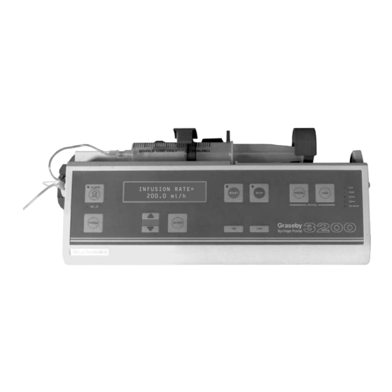
Smiths Medical International Ltd. Introduction CHAPTER 1 INTRODUCTION, FEATURES and SPECIFICATION Introduction The 3200 is a microcomputer controlled syringe pump that has primarily been developed for the neonatal infusion of sterile liquids. The pump has an In-line (wet-side) pressure sensing system for accurate occlusion detec- tion. - Page 17 Introduction Smiths Medical International Ltd. Figure 1.1 Itemised front view of the pump 1 — 2 Issue 5 (August 2004) 3200 Service Manual...
-
Page 18: Features
Smiths Medical International Ltd. Features Features The key features of the 3200 are as follows: • In-line (wet-side) pressure sensing, • automatic syringe size sensing, • up to 1500 History events storage, • universal AC supply powered or battery powered, •... -
Page 19: Specification
The power supply uses primary switching in order to utilise the AC supplies of most countries. Battery type: Sealed lead acid, rechargeable (Cyclon, 3 off). Smiths Medical recommend that the batteries are checked at least annually (see page 5-10). Battery life: More than 2.5 hours of normal pump operation when the batteries are fully charged. -
Page 20: In-Line Occlusion Pressure Range
Smiths Medical International Ltd. Specification Specification (contd.) In-line occlusion Using a 30 ml sized syringe: pressure range: 0 to 7.42 kg (1000 mmHg). 0 to 1355 cmH 0 to 133.3 kPa. 0 to 1316 mBar. 0 to 19.34 psi. Using a 50 ml syringe, 0 to 4.83 kg (0 to 650 mmHg). - Page 21 3400 remained. A DC input supply (10 V to 28 V DC) version of the 3200 is also manufactured by Smiths Medical. This variant is primarily intended for use in an aviation environment, but may be utilised in an environment where the required DC voltage exists.
-
Page 22: Configuration, Diagnostics And Occlusion Thrust
CHAPTER 2 CONFIGURATION, DIAGNOSTICS and OCCLUSION THRUST 3200 In-line Pressure Syringe Pump... -
Page 23: Configuration Mode
Smiths Medical International Ltd. Configuration mode CHAPTER 2 CONFIGURATION, DIAGNOSTICS and OCCLUSION THRUST Configuration mode WARNING The Configuration mode must only be used by personnel who are adequately qualified and have had previous training in the use of the 3200. -
Page 24: Entry Into The Configuration Mode
Configuration mode Smiths Medical International Ltd. Entry into the Configuration mode With the pump switched on and in the set-up mode, complete the following procedures to enter the Configuration mode. Press and hold down the PURGE button. Press either the ▲ or ▼ button. The following is... -
Page 25: Available Configuration Mode Parameters And Settings
Smiths Medical International Ltd. Configuration mode Available Configuration mode parameters and settings Syringe brands 1. WARNING The pump must be set to operate with the brand and size of syringe that is going to be used. Using a different brand to that selected could lead to the incorrect amount of drug being administered, resulting in injury or death. -
Page 26: Select Pump Modes
Configuration mode Smiths Medical International Ltd. Select pump This parameter shows the versatility of the 3200 by allowing five different combina- modes tions of the three modes of infusions to be pre-selected. Choice: ALL MODES AVAILABLE CONTINUOUS & PRESET INTERMITTENT ONLY... -
Page 27: Use Pressure Transducer
Smiths Medical International Ltd. Configuration mode Use pressure 16. This parameter allows a selection of in-line pressure sensing options. transducer If YES is chosen, the pump senses the presence of a syringe extension set and shows the in-line pressure on the display. -
Page 28: Communication Mode
NONE... this choice ensures that a computer cannot be used to monitor the pump. Contact Smiths Medical (Customer Support) for information on setting up a computer link. Pump ID The identification (ID) of the pump appears on the initial power up display. It also appears on the printout. -
Page 29: Diagnostic Mode
Smiths Medical International Ltd. Diagnostic mode WARNING Diagnostic The Diagnostic mode must only be used by personnel who are adequately mode qualified and have been trained in the use of the 3200. Introduction The Diagnostic mode has seven available options which can be used to view, select and complete the procedures detailed in the following sections. -
Page 30: Diagnostic Displays
Diagnostic mode Smiths Medical International Ltd. Diagnostic displays The software display shows the version of software installed in the pump. It is similar to Software the following display: SOFTWARE VERSION= 2.30 Calibrate To calibrate the transducer, both a syringe extension set and a mercurial sphygmomanometer transducer (or a similar pressure reading device) are used. -
Page 31: Transducer Alarm
Smiths Medical International Ltd. Diagnostic mode After carrying out the previous display request (i.e. pressing START), press STOP to return the pump to its set-up mode. Transducer If a fault occurs within the transducer set-up system, a pulsing loud alarm (silenceable) -
Page 32: Setting The Clock
Setting the clock Smiths Medical International Ltd. Setting the clock The time and date may be viewed; if required, both may be reset. The procedures for entering and setting the clock are detailed below. Entering the Simultaneously press the... clock display... -
Page 33: Disassembly And Assembly Of Casing
Smiths Medical International Ltd. Opening the pump casing Disassembly and assembly of casing WARNING The following procedures must only be carried out by qualified technicians. ELECTRIC SHOCK HAZARD The pump must be disconnected from the AC power supply before opening the casing. -
Page 34: Occlusion Measurements
Occlusion thrust Smiths Medical International Ltd. Occlusion The two most frequently used methods to measure the point at which an occlusion occurs are the thrust and pressure methods. measurements Currently, the occlusion is set in the factory by using a thrust measurement procedure. -
Page 35: Thrust Checks
Smiths Medical International Ltd. Occlusion thrust Thrust checks The following thrust checks use the weights that correspond to the factory-set occlusion threshold levels for a 3200 (i.e. 3.5 and 4.2 kg). If a different occlusion level setting is required, the weights must be adjusted accordingly. -
Page 36: Thrust Adjustments
Occlusion thrust Smiths Medical International Ltd. If the occlusion thrust requires adjustment, the following procedures must be completed: Thrust adjustments Switch the pump off and disconnect the AC supply. Take the casing apart (see page 2-11). If necessary, rotate the leadscrew to reveal the grub screw located on the occlusion adjusting nut. -
Page 37: Functional Descriptions
CHAPTER 3 FUNCTIONAL DESCRIPTIONS 3200 In-line Pressure Syringe Pump... -
Page 38: Introduction
Smiths Medical International Ltd. Functional descriptions CHAPTER 3 FUNCTIONAL DESCRIPTIONS Introduction This Chapter explains how the 3200 operates. Reading this chapter will help a technician to rectify any possible faults that may occur within the pump. The functional descriptions of the 3200 may be divided into six separate areas. Each of these functional descriptions are detailed separately in the sections following this list: •... -
Page 39: Plunger Clamp
Occlusion system Smiths Medical International Ltd. Plunger clamp When the plunger clamp is pulled down, the half nut/super nut engages with the leadscrew and the clamp engages with the end of the syringe. The syringe plunger slots into place behind a slotted pair of lips. These lips prevent the syringe plunger from moving forward in the event of negative pressure on the syringe. -
Page 40: Electro/Mech Control System
Smiths Medical International Ltd. Electro/mech control system The above action causes a voltage proportional to the pressure in the infusion line to be input to one of the channels of the 8 bit A-to-D converter in the micro-controller. If the output from the A-to-D converter exceeds the predetermined value set by the user, an in-line occlusion alarm is generated. -
Page 41: Battery Voltage Low
Sensing (alarm) systems Smiths Medical International Ltd. Battery voltage The sensing circuits incorporate a system that monitors the output of the batteries and registers an alarm if the voltage of the batteries drops below 5.75 V. If the voltage falls below 5.4 V the pump turns itself off after an initial warning period. -
Page 42: Cannot Zero Extension Set
Smiths Medical International Ltd. Software Cannot zero When the pump is switched on with a disposable syringe extension set fitted, the user is extension set alerted that an auto zero has not been carried out. An alarm is generated if an extension set calibration is unsuccessful. -
Page 43: Circuit Descriptions
CHAPTER 4 CIRCUIT DESCRIPTIONS 3200 In-line Pressure Syringe Pump... -
Page 44: Introduction
Smiths Medical International Ltd. Circuit descriptions CHAPTER 4 CIRCUIT DESCRIPTIONS Introduction This Chapter describes the action of the circuits that operate the 3200. It also shows the associated circuit diagrams and circuit board layouts. The 3200 contains six circuit boards as follows: •... -
Page 45: Processor Core
Processor core Smiths Medical International Ltd. The processor has the ability to address both the paged RAM and the EPROM. The 32K RAM (IC12) is split into four 8K pages, and the EPROM (IC13) is divided into thirty-two 8 K pages. The paging system is part of the integral memory management system of the processor. -
Page 46: Motor Interface
Smiths Medical International Ltd. Motor interface Motor interface The stepper motor is controlled by a sequence of pulses supplied from the main processor. A common ENABLE_MOTOR signal (see Figure 4.4) and one of the four motor control lines are fed to each AND gate. When the ENABLE_MOTOR signal is high, a pulse on one of the motor control lines will cause one of the four power mosfet’s to be switched on, and the resulting... -
Page 47: Sensors Interface
Sensors interface Smiths Medical International Ltd. Sensors The seven opto-sensors are split into three groups (see Figure 4.6) and these three groups are interface multiplexed onto three lines into the microprocessor. The three groups are used as follows: • One group is used by the size sensor board. -
Page 48: Rs232 Serial Interface
Smiths Medical International Ltd. RS232 interface RS232 serial WARNING interface Only items of equipment that conform to EN60950 may be connected to the 9-pin RS232 connector that is situated at the rear of the pump. This conformity prevents the safety of the patient being compromised. -
Page 49: Input/Output Serial Interface
Input/output serial interface Smiths Medical International Ltd. The remaining five output lines on IC8 are used to activate transistors Q9 to Q13 inclusive, and these transistors control the illumination of the syringe size indication LEDs, D17 to D21. The outputs from IC9 are used to control which group of opto-sensors are activated and also to activate transistors Q14, Q15, and Q16: these transistors control the illumination of the ALARM, START and STOP LEDs. -
Page 50: Pl 11 Output
Smiths Medical International Ltd. Regulator board Once the switch-mode controller has started working, it obtains its power supply from a bootstrap winding on pins 2 and 3 on the transformer. The power supply from the bootstrap winding is rectified by diode D5, smoothed by C13 and regulated by the Zener diode D6. -
Page 51: Setting Rv1
Smiths Medical International Ltd. Setting RV1 Setting RV1 The procedure for setting potentiometer RV1 is as follows: Switch off the external AC power, remove the pump’s power connector and open the casing (see page 2-11). Remove plug PL11 and PL12 from the Regulator board and connect a 68 ohm, 1 watt resistive load across pins 2 and 3 of plug PL11. -
Page 52: Syringe Size Sensors
Smiths Medical International Ltd. Syringe size and status sensors Syringe size The syringe size sensors board is physically located at the centre of the lower casing. The circuit diagram for these sensors is shown in Figure 4.14. The layout of the components sensors are shown in Figure 7.6. - Page 53 Overall block diagram Smiths Medical International Ltd. MOTOR SOUNDER RS 232 (Figure 4.19) DISPLAY OPTO SENSORS BOARD (Figure 4.15) MAIN DISTRIBUTION BOARD BOARD CONNECTIONS (Figures (Figure 4.16) Umbilical 4.3 to 4.10 and 7.5) connector SYRINGE SIZE SENSOR MEMBRANE BOARD SWITCH PANEL (Figure 4.14)
- Page 54 Smiths Medical International Ltd. Main board block diagram UM[0..26] RS232 SERIAL INTERFACE (See Fig. 4.8) POWER CONTROL (See Fig. 4.5) UM[0..26] HANDSHAKE_IN POWER ON MOTOR INTERFACE (See Fig. 4.4) HANDSHAKE_OUT UM[0..26] POWER OFF UM[0..26] MOTORSENSE1 MOTORCTL[0..3] MOTORSENSE0 ENABLE_MOTOR PROCESSOR CORE (See Fig.
- Page 55 Processor core Smiths Medical International Ltd. SENSE[0..7] SENSE[0..7] D[0..7] SENSE0 SENSE1 SENSE2 SENSE3 SENSE4 IC14 (MICRO-PROCESSOR) CLOCK PULSES SENSE5 SENSE6 100nF EXTAL IC3/PA0 SENSE7 220P 22pF IC2/PA1 IC1/PA2 A[0..18] OC5/IC4/OC1/PA3 IC13 (EPROM) OC4/OC1/PA4 16MHz OC3/OC1/PA5 XTAL OC2/OC1/PA6 22pF PAI/OC1/PA7 HANDSHAKE_OUT...
- Page 56 Smiths Medical International Ltd. Motor interface MOTORCTL[0..3] MOTORCTL[0..3] 1N4448 1N4448 1N4448 1N4448 10uF 100nF MOTOR3 MOTOR4 IC17A MOTORCTL0 74HC08 MOTOR5 IC17B MOTORCTL1 74HC08 VN0300M VN0300M VN0300M VN0300M MOTOR6 IC17C MOTORCTL2 74HC08 IC17D MOTORCTL3 100nF 100nF UM[0..26] ENABLE_MOTOR UM[0..26] 74HC08 R86D...
- Page 57 Power control Smiths Medical International Ltd. CONSTANT 100nF VOLTAGE Vcc') 100K 560R BC184L AC LED IC3D VCC' TSC05 AMBER 4093B 100K TSC04 100nF DISPLAY (VFD) REGULATION POWER MOSFET LM2940CT5 RFD8P05 VFDPWR RFD8P05 10uF DCSW 100nF 100nF 100K 1N4448 IC3A IC3B...
- Page 58 Smiths Medical International Ltd. Sensors and pressure sensing DCSW SENSE0 100nF PRESSURE SENSING (See Fig. 4-7) OFFSET_TRIM OFFSET_TRIM SENSE1 PRESSURE UM13 PRESSURE+ SENSE2 PRESSURE+ PRESSURE_OK PRESSURE- PRESSURE- SENSE3 MOTORSENSE0 SENSE4 MOTORSENSE1 UM19 OPT0 SENSE5 UM17 OPT1 SENSE6 UM15 OPT2 SENSE7 SENSE[0..7]...
- Page 59 Pressure sensing interface Smiths Medical International Ltd. OFFSET_TRIM 10uF IC1B 220K 1% PRESSURE+ 100K 100nF TLC279 100nF IC1A 100K 1% 10K 1% 10K 1% PRESSURE TLC279 100K 1% 10K 1% IC1C 100nF PRESSURE- 220K 1% TLC279 100K 100nF 100nF IC1D...
- Page 60 Smiths Medical International Ltd. RS232 interface 100nF VCC(+) 10uF 10uF UM16 T1IN T1OUT R34A UM12 HANDSHAKE_OUT T2IN T2OUT R34B UM14 R1OUT R1IN R34C UM10 HANDSHAKE_IN R2OUT R2IN R34D GND(-) MAX232 10uF 10uF SER_GND 100uH +10V UM[0..26] UM[0..26] GM0375-A Figure 4.8 RS232 interface circuit diagram 4 —...
- Page 61 Umbilical cable connections Smiths Medical International Ltd. Umbilical Connections OPTDRV2 UM22 OPTDRV0 UM20 UM19 OPT0 OPTDRV1 UM18 UM17 OPT1 UM16 UM15 OPT2 UM14 UM13 PRESSURE+ UM12 UM10 MOTOR3 SER_GND MOTOR4 PRESSURE- MOTOR5 MOTOR6 HEADER 13X2 UM[0..26] UM[0..26] GM0374-A Figure 4.9 Umbilical cable connections 4 —...
- Page 62 Smiths Medical International Ltd. Input/output serial interface KEYBOARD DCSW HEADER 10 1 2 3 4 5 6 7 8 9 R70A 100nF GREEN GREEN GREEN GREEN GREEN 100K* 3 X BAT85 FPSEL1 R66C A/QA R66B 560R 560R 560R 560R 560R...
- Page 63 Overview of the regulator Smiths Medical International Ltd. Isolation Components ISOLATED Circuits - Secondary (See Fig.4-13) LIVE Circuits - Primary (See Fig. 4-12) OUT2 LIVE LIVE PL11 SPADE System MAINS OK 220P/1kV 220R DC OUT ESD GND NEUTRAL 220R NEUTRAL...
- Page 64 Smiths Medical International Ltd. Regulator live (primary) EMC Filter LIVE T500mA W06G OUT1 470N/X 2x47mH 120R-1A 47U/400V NEUTRAL COMSIG COMPWR SENSE2 SENSE1 BOOT1 11DQ10 BOOT2 1U/35V COMSIG Switching MOSFET COMSIG COMSIG OUT2 BUZ80 COMP SENSE 470R VREF OSC1 COMSIG 330K...
- Page 65 Regulator isolated (secondary) Smiths Medical International Ltd. Output Filter Feedback Reference Output Crowbar Protection MAINS OK 1N4001 DC OUT 1 Amp PBYR745 (Heatsink mounted) BATT+ 1K5 TH 2 Amp 3K6 1% 220R TL431 470R 470K 2K2 1% TIC106B BC184L 2U2/50V...
- Page 66 Smiths Medical International Ltd. Syringe and status sensors OPT1 SIZE SENSOR B GM0338-A Figure 4.14 Syringe size sensors circuit diagram GUARD RAIL OPTO0 END OF TRAVEL DETECTOR OPTO1 OCCLUSION DETECTOR OPTO2 DRIVE ENGAGEMENT DETECTOR Note: Cableform is hardwired CHOKE GM0095-A Figure 4.15 Status sensors circuit diagram...
- Page 67 Distribution board Smiths Medical International Ltd. UM22 UM20 UM19 UM18 UM17 UM16 UM15 UM14 UM13 UM12 UM11 UM10 UM11 MOTOR0 MOTOR MOTOR1 DRIVE MOTOR2 MOTOR3 MOTOR4 MOTOR5 HEADER 13X2 MOTOR6 CONN[0..26] HEADER 7 UM19 OPT0 OPTO UM17 OPT1 UM15 OPT2...
- Page 68 Smiths Medical International Ltd. Pressure sensing SOT2 PRESENCE DETECTOR HOA 1882-12 SOT1 HEADER 6 NOTE EITHER SOT1, SOT2 OR RV1 IS FITTED AS FACTORY ADJUSTMENT GM0389-A Figure 4.17 Pressure sensing circuit diagram 3200 Service Manual 4 — 25 Issue 5 (August 2004)
- Page 69 Membrane switch panel Smiths Medical International Ltd. HEADER 10 GROUND SCREEN START STOP HISTORY RESET ALARM PURGE DOWN ENTER GM0416-A Figure 4.18 Membrane switch panel circuit "D" CONN SER_GND NOTE: The RS232 Serial Interface connections to PL2 are shown on Fig. 4-18 GM0417-A Figure 4.19 Internal ribbon cable and ‘D’...
- Page 70 CHAPTER 5 FAULT CODES, CLEANING, RENEWAL of FUSES and REPAIRS 3200 In-line Pressure Syringe Pump...
-
Page 71: Fault Codes, Cleaning, Renewal Of Fuses And Repairs
Smiths Medical International Ltd. Fault codes and repairs CHAPTER 5 FAULT CODES, CLEANING, RENEWAL of FUSES and REPAIRS Fault codes Comprehensive fault codes have been designed into the software of the 3200, and a fault code number has been allocated to each of the faults that may occur ( Table 5.1 ), thus making identification of a particular fault easy to trace and rectify. - Page 72 Fault codes Smiths Medical International Ltd. Fault codes Table 5.1 Main processor fault codes (contd.) (contd.) Code Fault Recommended action Interference or internal circuit See item 2, page 5-3 Interference or internal circuit See item 2, page 5-3 Interference or internal circuit...
- Page 73 Smiths Medical International Ltd. Fault codes Fault codes Table 5.1 Main processor fault codes (contd.) (contd.) Code Fault Recommended action Interference or internal circuit See item 2 below Interference or internal circuit See item 2 below Interference or internal circuit...
-
Page 74: Cleaning
Cleaning and changing fuses Smiths Medical International Ltd. Cleaning WARNING Do not immerse the pump in any liquids. Immediately wipe off any liquid that may be spilt on the pump. The outer surfaces of the pump can be cleaned by wiping them over with a damp cloth (soapy if necessary). -
Page 75: Main Board Renewal
Smiths Medical International Ltd. Repair procedures Main board The main board is mounted on the front casing. It is held in place by six pozi pan head renewal self-tapping screws. Open the casing (see page 2-11). Disconnect the umbilical connector (PL4) from the main board. -
Page 76: Plunger Clamp And Super Nut Assembly Renewal
Repair procedures Smiths Medical International Ltd. Plunger clamp The plunger clamp and super nut assembly is held in place (in the rear casing) by two guide and super nut tubes. assembly renewal Open the casing (see page 2-11). Remove and retain the screw that holds the distribution board tray in place. -
Page 77: Motor And Gearbox Assembly Renewal
Smiths Medical International Ltd. Repair procedures Motor and There is a plastic coupling between the leadscrew and the gearbox. gearbox assembly Open the casing (see page 2-11). renewal Carefully prise open the motor loom retain clip and then disconnect the motor loom connector (PL4) from the distribution board. -
Page 78: Membrane Switch Panel Renewal
Repair procedures Smiths Medical International Ltd. Membrane The membrane switch panel has an adhesive backing which fixes it to the casing. Take switch panel care not to unduly bend the new panel or its flexible cable loom. renewal Open the casing (see page 2-11). -
Page 79: Syringe Size Sensors Assembly Renewal
If the pump fails to pass the syringe size sensors test it is recommended that the Syringe Size Sensors kit (part number 0137-0025) should be obtained from Smiths Medical and fitted according to the instructions supplied with the kit (also see the Appendix). -
Page 80: Batteries. Checks And Replacement
If an old style front or rear case becomes damaged and requires replacing then the appropriate repair kit is available from Smiths Medical. There are two kits (front or rear case) which each contain all the necessary parts to carry out a repair. -
Page 81: Front Case Spares Kit
Smiths Medical International Ltd. Spares kits Table 5.3 Front case spares kit Description Part No. Remarks Front case spares kit- English 0130-0192 Front case spares kit- Other 0130-0165 Case front 0130-0163 Syringe clamp assembly* 0131-0149 Button, moulded* 0131-0216 2 off... -
Page 82: Rear Case Spares Kit
Smiths Medical International Ltd. Table 5.5 Rear case spares kit Description Part No. Remarks Rear case spares kit* 0130-0171 Case rear 0130-0188 Pressure sensing insulat. film 0130-0031 Foam spacer type 1* 0131-0204 Foam spacer type 2* 0131-0205 3 off Foot, rubber*... -
Page 83: Functional Tests
CHAPTER 6 FUNCTIONAL TESTS and MANUFACTURNG SETTINGS 3200 In-line Pressure Syringe Pump... - Page 84 Smiths Medical manufacture a set of 18 Syringe Size Sensor gauges, part number 0131-0202 (see Appendix, page A-5). The Smiths Medical Customer Care Department is able to take orders for these gauges and will supply the current price. This set of gauges enables test No. 4 to be carried out on all of the Graseby 3000 Series of pumps.
- Page 85 Functional tests Smiths Medical International Ltd. Table 6.1 Functional tests (contd.) Step Test Method Correct result 5(i) Keyboard tests. Press OFF. The display is blank but the AC AC connected. LED remains lit. 5(ii) Press ON. As above (3), Initial power on.
- Page 86 Smiths Medical International Ltd. Functional tests Table 6.1 Functional tests (contd.) Step Test Method Correct result Linear accuracy. Set the following: Check that the plunger clamp moves • syringe type to 60 ml BD a distance of 18 ±0.3 mm.
-
Page 87: Plunger Clamp Alarm Checks
Plunger clamp alarm checks Smiths Medical International Ltd. Plunger clamp The following plunger clamp alarm checks are only required on pumps fitted with the old style half nut, and not the more recent super nut (see page 5-8). alarm checks The dual ramp gauge ( part number 0131-0084 ) is used to check that the .. -
Page 88: Linear Accuracy
Smiths Medical International Ltd. Linear accuracy Linear accuracy The linear accuracy gauge ( Figure 6.3, part number 0131-0230 ) when placed on the pump, is able to check that the pump's plunger clamp moves a given distance in a specified time. -
Page 89: Manufacturing Settings
Manufacturing settings Smiths Medical International Ltd. Manufacturing When the tests of Table 6.1 have been completed, the pump can be returned to the manufacturing settings (if required) as shown in sequence in Table 6.2. settings The settings marked with an asterisk ( ) in Table 6.2 are intermediate settings that are initially... - Page 90 Smiths Medical International Ltd. Manufacturing settings Table 6.2 Manufacturing settings (contd.) Option Setting Configuration mode: Select pump modes CONTINUOUS & PRESET Preset volume mode with time Allow mass units Set-up mode: Infusion mode PRESET VOLUME Infusion rate 1.0 ml/h Preset Volume 0.2 ml...
- Page 91 CHAPTER 7 ILLUSTRATED PARTS LIST 3200 In-line Pressure Syringe Pump...
-
Page 92: Illustrated Parts Lists
3200 Illustrated Parts List Smiths Medical International Ltd. CHAPTER 7 ILLUSTRATED PARTS LISTS Figure 7.1 General assembly Item Description Part number Remarks Model 3200 - English 0130-0001 - 110 V model 0130-0701 - Italian 0130-0704 - Spanish 0130-0705 - German... -
Page 93: Leadscrew Assembly
Smiths Medical International Ltd. 3200 Illustrated Parts List Figure 7.1 General assembly (contd) Item Description Part number Remarks Rear panel instruction label - see table below IMPORTANT: When ordering a CE marked rear label, please supply the serial number details of the Syringe Pump, if this information is not supplied then a Non-CE marked label will be issued. - Page 94 Smiths Medical International Ltd. 3200 Illustrated Parts List Figure 7.1 General assembly 3200 Service Manual Issue 5 (August 2004) 7 — 3...
- Page 95 3200 Illustrated Parts List Smiths Medical International Ltd. 7 — 4 Issue 5 (August 2004) 3200 Service Manual...
- Page 96 3200 Illustrated Parts List Smiths Medical International Ltd. Figure 7.1 General assembly (contd) Item Description Part number Remarks Size sensors PCB assembly 0130-0017 Cable assembly size sensor 0053-0678 Distribution board assembly 0130-0027 Cable assembly - Distribution to Main board 0053-0687 Pole clamp assembly see Figure 7.3a...
- Page 97 Smiths Medical International Ltd. 3200 Illustrated Parts List Figure 7.1 General assembly (contd) Item Description Part number Remarks 5/10 ml adaptor plate 0132-0076 Germany only Perfusor conversion kit 0131-0048 Not illustrated. Kit contains the following items: Perfusor spacer tube, see Chap. 8 for nearly empty flag for Perfusor, Plunger clamp plate, ‘P’...
- Page 98 3200 Illustrated Parts List Smiths Medical International Ltd. Figure 7.2 Plunger clamp and half nut assembly Item Description Part number Remarks Plunger clamp and tube 0127-0044 Plunger clamp cover and internal kit 0131-0239 Kit contains: Plunger clamp cover, Plunger clamp lock, Plunger clamp pin,...
- Page 99 Smiths Medical International Ltd. 3200 Illustrated Parts List Fig. 7.3a Pole clamp assembly: non-rotating Item Description Part number Remarks Pole clamp assembly (new version) 0131-0129 Pole clamp cap-knob 788098-2890-4 Figure 7.3a Pole clamp assembly - Non-rotating 7 — 8 3200 Service Manual...
- Page 100 3200 Illustrated Parts List Smiths Medical International Ltd. Fig. 7.3b Pole clamp assembly: Rotating Item Description Part No. Remarks Rotating pole clamp assembly 0131-0083 Securing plate 0131-0074 Locating ring 0127-0064 Handle 0127-0060 Pole clamp body 0131-0061 Crescent circlip 5030-5710 External circlip type 7100-010...
- Page 101 Smiths Medical International Ltd. 3200 Illustrated Parts List Figure 7.4 Leadscrew assembly Item Description Part number Remarks Leadscrew and half nut kit comprising: 0131-0236 Leadscrew assembly, Half nut casting, 2 different flags, 1 screw, 1 nut and Instruction sheet Half nut casting...
- Page 102 3200 Illustrated Parts List Smiths Medical International Ltd. Figure 7.5 Main board assembly Item Description Part number Remarks 3200 Main board assembly 0130-0009 Sounder 3430-1205 Sounder restraint kit comprising: 0131-0240 Kit contains: Nut M3 - 2 off, Screw M3 x 16 - 2 off, Pillar - 2 off...
- Page 103 Smiths Medical International Ltd. 3200 Illustrated Parts List IC17 IC12 D 11 IC13 IC16 D21 D20 D19 D18 GM0213-C Figure 7.5 Main board assembly 7 — 12 3200 Service Manual Issue 5 (August 2004)
-
Page 104: Regulator Board Assembly - Ac Power
3200 Illustrated Parts List Smiths Medical International Ltd. Figure 7.6 Regulator board assembly - AC Power Item Description Part number Remarks Regulator board assembly - AC power 0130-0013 Fuse cover 3412-0228 FS1, Fuse F1A 5 x 20 mm, 3410-3705 BUSSMANN S500... -
Page 105: Braun Perfusor Conversion
CHAPTER 8 BRAUN PERFUSOR CONVERSION 3200 In-line Pressure Syringe Pump... -
Page 106: Syringe Conversion Procedures
Smiths Medical International Ltd. Braun Perfusor conversion CHAPTER 8 BRAUN PERFUSOR CONVERSION Syringe conversion procedures Introduction The 3200 can, if required, easily be converted to use the ‘Braun Perfusor 50 ml syringe’. The Perfusor conversion kit part number is 0131-0048. -
Page 107: Reselecting 'Various' Syringe Brands
Braun Perfusor conversion Smiths Medical International Ltd. Reselecting ‘various’ syringe brands Mechanical To reselect the various syringe brands carry out the following mechanical and procedures programming procedures: Take the case apart (see page 2-5). Replace the original standard nearly empty flag. -
Page 108: Dc Input Version Of 3200
CHAPTER 9 DC INPUT VERSION of 3200 3200 In-line Pressure Syringe Pump... -
Page 109: Introduction
Smiths Medical International Ltd. DC input variant CHAPTER 9 DC input version of 3200 Introduction The following information is intended for users of the DC version of the 3200. The DC pump is primarily intended for use in an aviation environment, but may also be used in other environments such as ambulances. - Page 110 Circuit diagram of DC PSU Smiths Medical International Ltd. MX 1 100R MOLEX 4 TSF1 + ve FAST ON1 3 AMP 1 AMP IN4148 SB540 FITTED PT 6302 MX 2 EMC FILTER EMC FILTER V IN V OUT 2 AMP...
-
Page 111: Appendix
APPENDIX FITTING a MODIFIED SIZE SENSOR FLAG 3200 In-line Pressure Syringe Pump... -
Page 112: Fitting A Modified Size Sensor Flag
In a continual and ongoing programme of improvements to their 3000 range of syringe pumps, Smiths Medical engineers have introduced a modified Syringe Size Flag (SSF) 1 that allows the size sensor mechanism to be accurately aligned (see Figure A) . -
Page 113: Opening The Case
When a new SSF has been fitted to a pump, the pump must be tested using the Syringe Size Sensor gauges ( part number 0131- 0202 ) available from Smiths Medical. Page A-3 gives details of the Final Testing procedures. -
Page 114: Reassembly
The shim sizes provided in the kit are 0.6, 1.0, 1.2 and 1.4 mm. If necessary, use a combination of shims to obtain the thickness required, up to a maximum of 2.4 mm. During production at Smiths Medical, a 1.6 mm shim is initially fitted to the pump. -
Page 115: Setting The Size Sensor Flag
SSF, Appendix Smiths Medical International Ltd. Setting the size sensor flag Using the 3200 size sensor test gauges (see page A-5), fit the white 20 ml minimum sensor gauge ( part number 0131-0170 ) into pump's cradle and observe whether (a) or (b) occurs: If the pump indicates that a 20 ml gauge is fitted, complete steps (2) to (5). - Page 116 Smiths Medical International Ltd. Appendix, SSF Apply a small amount of loctite 414 to the security cap Apply a small amount of loctite 7400 to the thread of the grub screw prior to setting GM1111-A Figure A.3 Size Sensor Flag: general details The Size Sensor Gauge set ( part number 0131-0202 ) contains the gauges that are used to carry out the Size Sensor tests.
- Page 117 The details given in this Manual are correct at the time of going to press. The company, however, reserves the right to improve the equipment shown. For further information, please contact your local distributor or Smiths Medical direct on +44 (0)1923 246434 Smiths Medical International Ltd.
Need help?
Do you have a question about the Graseby 3200 and is the answer not in the manual?
Questions and answers