Sign In
Upload
Manuals
Brands
SMC Corporation Manuals
Servo Drives
LECSA series
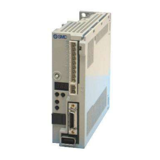
SMC Corporation LECSA series Motor Driver Manuals
Manuals and User Guides for SMC Corporation LECSA series Motor Driver. We have
1
SMC Corporation LECSA series Motor Driver manual available for free PDF download: Operation Manual
SMC Corporation LECSA series Operation Manual (419 pages)
AC Servo Motor Drive
Brand:
SMC Corporation
| Category:
Servo Drives
| Size: 11 MB
Table of Contents
Appendix App.- 1 to App.-15
32
Driver ····························································································································
5
Signals ·······················································································································
7
Parameters ················································································································
10
Connector ······················································································································
12
Parameters ··············································································································
17
Table of Contents
32
Functions and Configuration
34
Introduction
34
Function Block Diagram
36
Driver Standard Specifications
39
Function List
41
Applicable Control Mode for each Actuator
43
Model Code Definition
44
Combination with Servo Motor
46
Parts Identification
47
Configuration Including Auxiliary Equipment
48
2. Installation
49
Installation
50
Installation Direction and Clearances
51
Keep out Foreign Materials
52
Cable Stress
53
Inspection Items
53
Parts Having Service Lives
54
Table of Contents
55
Signals and Wiring
56
Input Power Supply Circuit
57
I/O Signal Connection Example
59
Position Control Mode
59
Internal Speed Control Mode
61
Internal Torque Control Mode
62
Explanation of Power Supply System
63
Signal Explanations
63
Power-On Sequence
63
CNP1 and CNP2 Wiring Method
65
Connectors and Signal Arrangements
68
Signal Explanations
71
Detailed Description of the Signals
78
Position Control Mode
78
Internal Speed Control Mode
81
Internal Torque Control Mode
84
Position/Speed Control Change Mode
87
Internal Speed/Internal Torque Control Change Mode
88
Internal Torque/Position Control Change Mode
89
Alarm Occurrence Timing Chart
90
Interfaces
91
Internal Connection Diagram
91
Detailed Description of Interfaces
92
Source I/O Interfaces
95
Treatment of Cable Shield External Conductor
96
Connection of Driver and Servo Motor
97
Connection Instructions
97
Power Supply Cable Wiring Diagrams
98
Servo Motor with a Lock
99
Safety Precautions
99
Setting
99
Timing Charts
100
Wiring Diagrams (LE-□-□Series Servo Motor)
102
Grounding
104
Table of Contents
105
Parameters
106
Basic Setting Parameters (No. PA )
107
Parameter List
107
Parameter Write Inhibit
108
Selection of Control Mode
109
Selection of Regenerative Option
110
Selection of the Tough Drive Function
111
Number of Command Input Pulses Per Servo Motor Revolution
112
Electronic Gear
113
Auto Tuning
117
In-Position Range
118
Torque Limit
119
Selection of Command Input Pulse Form
120
Selection of Servo Motor Rotation Direction
121
Encoder Output Pulses
122
Parameters
107
Gain/Filter Parameters (No. PB )
125
Parameter List
125
Detail List
127
Position Smoothing
135
Extension Setting Parameters (No. PC )
136
Parameter List
136
List of Details
138
Alarm History Clear
145
Drive Recorder Function
146
I/O Setting Parameters (No. PD )
150
Parameter List
150
List of Details
151
Using Forward/Reverse Rotation Stroke End to Change the Stopping Pattern
162
5. Display and Operation Sections
163
Display and Operation Sections
164
Overview
164
Display Sequence
165
Status Display
166
Display Transition
167
Display Examples
168
Status Display List
170
Diagnostic Mode
172
Alarm Mode
174
Point Table Mode·············································································································
176
Point Table Mode Setting Screen Sequence
177
Operation Example
178
Parameter Mode ············································································································
180
Operation Example
181
External I/O Signal Display
183
Output Signal (DO) Forced Output
186
Test Operation Mode
187
Mode Change
187
Jog Operation
188
Positioning Operation
189
Motor-Less Operation
191
Forced Tough Drive Operation
192
One-Touch Tuning
192
6. General Gain Adjustment
193
General Gain Adjustment
195
One-Touch Tuning Procedure
195
Display Transition and Operation Procedure of the One-Touch Tuning
196
Precautions for One-Touch Tuning
200
Gain Adjustment Methods
201
Auto Tuning Mode
203
Overview
203
Auto Tuning Mode 1 Operation
204
Adjustment Procedure by Auto Tuning
205
Response Level Setting in Auto Tuning Mode 1
206
2-Gain Adjustment Mode
207
Manual Mode
208
7. Special Adjustment Functions
211
Special Adjustment Functions
212
Tough Drive Function
212
Overload Tough Drive Function
212
Vibration Tough Drive Function
213
Instantaneous Power Failure Tough Drive Function
215
Machine Resonance Suppression Function
217
Function Block Diagram
217
Adaptive Filter
218
Machine Resonance Suppression Filter
220
Advanced Vibration Suppression Control
221
Applications
225
Parameters
227
Gain Changing Operation
229
10. Characteristics
269
Characteristics
270
Overload Protection Characteristics
270
Power Supply Capacity and Generated Loss
271
Dynamic Brake Characteristics
273
Dynamic Brake Operation
273
Cable Flexing Life
275
Inrush Currents at Power-On of Main Circuit and Control Circuit
275
11. Options and Auxiliary Equipment
276
Cable/Connector Sets
277
Combinations of Cable/Connector Sets
277
Encoder Cable
277
Motor Cable
277
Lock Cables
283
Options and Auxiliary Equipment
277
Setup Software
287
Selection Example of Wires
289
No-Fuse Breakers, Fuses, Magnetic Contactors
291
Noise Reduction Techniques
292
Leakage Current Breaker
298
Surge Protector (Recommended)
301
12. Servo Motor
303
Servo Motor
304
Servo Motor with a Lock
304
Characteristics of Servo Motor with a Lock
306
Protection from Oil and Water
307
Cable
307
Rated Speed of Servo Motor
307
Mounting Connectors
308
Table of Contents
309
Positioning Mode
311
I/O Signal Connection Example
311
Connectors and Signal Arrangements
312
Signal Explanations
313
Detailed Description of the Signals
321
Automatic Operation Mode for Point Table Method
325
What Is Automatic Operation Mode
325
Automatic Operation Using Point Table
327
Automatic Operation Mode for Program Method
338
What Is Automatic Operation Mode for Program Method
338
Programming Language
339
Basic Setting of Signals and Parameters
354
Simple Language for Program Operation
356
Manual Operation Mode
358
JOG Operation
358
Home Position Return Mode
360
Outline of Home Position Return
360
Selection of Home Position Return Mode
361
Dog Type Home Position Return
362
Count Type Home Position Return
365
Data Set Type Home Position Return
367
Stopper Type Home Position Return
368
Home Position Ignorance (Servo-On Position as Home Position)
370
Dog Type Rear End Reference Home Position Return
371
Count Type Front End Reference Home Position Return
373
Dog Cradle Type Home Position Return
375
Home Position Return Automatic Return Function
377
Parameters
378
Basic Setting Parameters (No. PA )
378
Gain/Filter Parameters (No. PB )
378
Extension Setting Parameters (No. PC )
378
I/O Setting Parameters (No. PD )
389
Positioning Setting Parameters (No. PE )
391
Point Table Setting Method
397
Program Setting Method
399
Single-Step Feed Usage in the Test Operation Mode
402
Appendix
404
App. 1 Parameter List
405
App. 2 Servo Motor ID Codes
410
App. 3 Signal Layout Recording Paper
410
App. 4 Status Display Block Diagram
411
App. 5 Compliance with EC Directives
413
App. 5.1 What Are EC Directives
413
App. 5.2 Precautions for Compliance
413
App .6 Conformance with UL/CSA Standard
416
App. 6 Conformance with UL/CSA Standard
416
Advertisement
Advertisement
Related Products
SMC Corporation LEFS25
SMC Corporation LEFS32
SMC Corporation LEFB32
SMC Corporation LEFB32U
SMC Corporation LEJB63
SMC Corporation LEY25D
SMC Corporation LEYG25D
SMC Corporation LEY32D
SMC Corporation LEYG32
SMC Corporation LEY63
SMC Corporation Categories
Control Unit
Controller
Switch
Chiller
Servo Drives
More SMC Corporation Manuals
Login
Sign In
OR
Sign in with Facebook
Sign in with Google
Upload manual
Upload from disk
Upload from URL