
Related Manuals for SMC Corporation LECSA series

Summary of Contents for SMC Corporation LECSA series
- Page 1 Doc. no. LEC-OM02610 (Doc no. JXC※-OMT0023-A) PRODUCT NAME AC Servo Motor Driver MODEL / Series/ Product Number LECSA Series...
- Page 2 LECSA□-□ Series / Driver 1. Safety Instructions These safety instructions are intended to prevent hazardous situations and/or equipment damage. These instructions indicate the level of potential hazard with the labels of “Caution,” “Warning” or “Danger.” They are all important notes for safety and must be followed in addition to International Standards (ISO/IEC)*1), and other safety regulations.
- Page 3 Note that the CAUTION level may lead to a serious consequence according to conditions. Please follow the instructions of both levels because they are important to personnel safety. What must not be done and what must be done are indicated by the following diagrammatic symbols. Indicates what must not be done.
- Page 4 LECSA□-□ Series / Driver 1. Safety Instructions Caution The product is provided for use in manufacturing industries. The product herein described is basically provided for peaceful use in manufacturing industries. If considering using the product in other industries, consult SMC beforehand and exchange specifications or a contract if necessary.
-
Page 5: Driver ····························································································································
1. To prevent electric shock, note the following WARNING Before wiring, be sure to turn off the power, wait for 15 minutes or longer, and then make sure that the charge lamp is off to prevent an electric shock. In addition, always confirm if the charge lamp is off or not from the front of the driver. - Page 6 4. Additional instructions The following instructions should also be fully noted. Incorrect handling may cause a fault, injury, electric shock, etc. (1) Transportation and installation CAUTION Carry the products in a suitable way according to their weights. Do not stack the product packages exceeding the maximum number specified on the package. Do not hold the lead of the built-in regenerative resistor when carrying the driver.
-
Page 7: Signals ·······················································································································
(2) Wiring CAUTION Before unplugging CNP1 connector from the driver, disconnect the lead of the built-in regenerative resistor from CNP1 connector first. Wire the equipment correctly and securely. Improper wiring may cause unexpected operation. Do not install a power capacitor, a surge absorber or a radio noise filter (FR-BIF: Mitsubishi Electric Corporation) between the servo motor and the driver. - Page 8 (4) Usage CAUTION Configure an external emergency stop circuit in order to stop the operation immediately and shut off the power. Do not disassemble or repair the equipment. If an alarm is reset while the operation signal is input to the driver, the equipment starts suddenly. Be sure that the operation signal is off before resetting the alarm to prevent an accident.
- Page 9 (6) Storing of servo motor CAUTION Note the following points when storing the servo motor for an extended period of time (guideline: three or more months). Be sure to store the servo motor indoors in a clean and dry place. If it is stored in a dusty or damp place, make adequate provision, e.g.
-
Page 10: Parameters ················································································································
About processing of waste When you discard converter unit, driver, servo motor, battery (primary battery), and other option articles, please follow the law of each country (area). FOR MAXIMUM SAFETY These products have been manufactured as a general-purpose part for general industries, and have not been designed or manufactured to be incorporated in a device or system used in purposes related to human life. - Page 11 <<About the manuals>> This Instruction Manual are required if you use the General-Purpose AC servo LECSA□-□ for the first time. Always purchase them and use the LECSA□-□ safely. <<About the wires used for wiring>> Wiring wires mentioned in this instruction manual are selected based on the ambient temperature of 40 (104 ).
-
Page 12: Connector ······················································································································
Introduction Introduction The LECSA□-□ series general-purpose AC servo is based on the LECSB□-□ series, and retains its high performance, with some limitations in functions. For details of functions, performance and specifications of the LECSB□-□ series, refer to chapters 1 to 12 and appendices of this Instruction Manual. This section describes the how-to (startup, actual operation, and others) for users who use the LECSA□-□... - Page 13 Introduction 1. Operation and setting Operation and settings of the driver are easily performed only on the display section (3-digit, 7-segment LED) and on the operation section (four pushbuttons and one-touch tuning button) located on the front panel of the driver.
- Page 14 Introduction 2. Startup When switching the power on for the first time, follow the startup procedure below. Refer to (1) in this section. Visual wiring check Surrounding environment Check the surrounding environment (cable routing and check impurity such as wire offcuts or metallic dust) of the driver and the servo motor.
- Page 15 Introduction (1) Visual wiring check Before switching on the main circuit and control circuit power supplies, check the following items. Power supply system wiring The power supplied to the power input terminals (L , +24V, 0V) of the driver should satisfy the defined specifications.
- Page 16 Introduction (2) Power on and off procedures (a) Power-on Switch the power on in the following procedure. Always follow this procedure at power-on. 1) Turn off the servo-on (SON). 2) Make sure that command and start signal from the PC or PLC...etc are not input. 3) Switch on the control circuit power supply.
-
Page 17: Parameters ··············································································································
Introduction The following shows the main parameters, which must be changed, among parameter No. PA PA01 Selection of control mode (refer to section 4.1.3) Select the control mode of the driver, and whether to enable or not the one-touch tuning function. Parameter No. - Page 18 Introduction PA13 Selection of command input pulse form (refer to section 4.1.11) Select the input form of the pulse train input signal. Command pulses may be input in any of three different forms, for which positive or negative logic can be chosen. Arrow in the table indicates the timing of importing a pulse train.
- Page 19 Introduction PA14 Selection of servo motor rotation direction (refer to section 4.1.12) Select servo motor rotation direction relative to the input pulse train. Servo motor rotation direction Parameter No. PA14 setting When forward rotation pulse is input When reverse rotation pulse is input Forward rotation (CCW) Reverse rotation (CW) (5) Operation confirmation before actual operation...
- Page 20 Introduction (6) One-touch tuning Just by pressing the "AUTO" button on the front panel of the driver during operation, the gain/filter is easily adjusted. (Refer to section 6.1.) Startup of system Rotate the servo motor by an external command device, Operation etc.
- Page 21 Introduction (7) Stop In any of the following statuses, the driver interrupts and stops the operation of the servo motor. Refer to section 3.11 for the servo motor with a lock. (a) Servo-on (SON) OFF The base circuit is shut off and the servo motor coasts. (b) Alarm occurrence When an alarm occurs, the base circuit is shut off and the dynamic brake activates to stop the servo motor immediately.
- Page 22 Introduction 3. Troubleshooting at startup Never adjust or change the parameter values extremely as it will make operation CAUTION instable. POINT You can refer to reasons for servo motor rotation failure, etc. using MR Configurator2 The following faults may occur at startup. If any of such faults occurs, take the corresponding action. (1) Troubleshooting Step of occurrence Fault...
- Page 23 Introduction № Step of occurrence Fault Investigation Possible cause Reference Switch on forward Servo motor does not Check the ON/OFF status of the LSP, LSN, ST1 or ST2 is off. Section rotation start (ST1) rotate. input signal on the external I/O or reverse rotation signal display (refer to section start (ST2).
- Page 24 Introduction (2) How to find the cause of position shift Controller Servo amplifier Driver PC or PLC…etc Machine (a)Output pulse Electronic gear (parameters No. PA06, PA07) counter Servo motor (d) Machine stop position M FBP conversion (b)Cumulative command pulses (Cause B) (Cause A) (Cause C) Servo-on (SON),...
- Page 25 Introduction 3) C Δ M (cumulative feedback pulses travel per pulse machine position) Check for a position shift in the following sequence. 1) When Q ≠ P Noise entered in the pulse train signal wiring between the PC or PLC...etc and driver, causing command input pulses to be miss-counted.
- Page 26 Introduction 4. Tough drive function Since the operation status of devices may be changed by the tough drive CAUTION operation, check for any problems before making this function valid. POINT For details of the tough drive function, refer to section 7.1. The tough drive function continues the operation not to stop a machine in such situations when normally an alarm is activated.
- Page 27 CONTENTS 1. FUNCTIONS AND CONFIGURATION 1 - 1 to 1 - 16 1.1 Introduction ............................... 1 - 2 1.2 Function block diagram ..........................1 - 4 1.3 Driver standard specifications ........................1 - 7 1.4 Function list ............................... 1 - 9 1.4.1 Applicable control mode for each actuator ..................
- Page 28 3.10 Connection of driver and servo motor ················································································ 3 -43 3.10.1 Connection instructions ····························································································· 3 -43 3.10.2 Power supply cable wiring diagrams ············································································ 3 -44 3.11 Servo motor with a lock ·································································································· 3 -45 3.11.1 Safety precautions ··································································································· 3 -45 3.11.2 Setting ··················································································································...
- Page 29 5.4 Diagnostic mode ············································································································· 5 -10 5.5 Alarm mode ··················································································································· 5 -12 5.6 Point table mode············································································································· 5 -14 5.6.1 Point table transition ·································································································· 5 -14 5.6.2 Point table mode setting screen sequence ······································································ 5 -15 5.6.3 Operation example ···································································································· 5 -16 5.7 Parameter mode ············································································································...
- Page 30 7.3.2 Function block diagram ······························································································ 7 -16 7.3.3 Parameters ·············································································································· 7 -17 7.3.4 Gain changing operation ····························································································· 7 -19 8. TROUBLESHOOTING 8 - 1 to 8 -33 8.1 Alarms and warning list ····································································································· 8 - 2 8.2 Remedies for alarms ········································································································ 8 - 4 8.3 Remedies for warnings ····································································································...
- Page 31 12.4 Rated speed of servo motor......................12- 5 12.5 Mounting connectors ........................12- 6 13. POSITIONING MODE 13- 1 to 13-95 13.1 Selection method of each operation mode ·········································································· 13- 2 13.2 Signals ······················································································································· 13- 3 13.2.1 I/O signal connection example ···················································································· 13- 3 13.2.2 Connectors and signal arrangements ··········································································...
-
Page 32: Table Of Contents
APPENDIX App.- 1 to App.-15 App. 1 Parameter list ········································································································· App.- 2 App. 2 Servo motor ID codes ······························································································ App.- 7 App. 3 Signal layout recording paper ····················································································· App.- 7 App. 4 Status display block diagram ····················································································· App.- 8 App. 5 Compliance with EC directives ··················································································· App.-10 App .6 Conformance with UL/CSA standard ···········································································... - Page 33 1. FUNCTIONS AND CONFIGURATION 1. FUNCTIONS AND CONFIGURATION ......................2 1.1 Introduction .............................. 2 1.2 Function block diagram ..........................4 1.3 Driver standard specifications ........................7 1.4 Function list .............................. 9 1.4.1 Applicable control mode for each actuator..................11 1.5 Model code definition ..........................
-
Page 34: Functions And Configuration
1. FUNCTIONS AND CONFIGURATION 1. FUNCTIONS AND CONFIGURATION 1.1 Introduction The LECSA□-□ series general-purpose AC servo is based on the LECSB□-□ series, and retains its high performance, with some limitations in functions. It has position control, internal speed control and internal torque control modes. Further, it can perform operation with the control modes changed, e.g. - Page 35 1. FUNCTIONS AND CONFIGURATION (4) Positioning mode The positioning mode has point table method and program method. (a) Point table method The positioning operation can be executed by setting the position data (the target position), the servo motor speed, the acceleration/deceleration time constant, etc. in the point table as if setting them in parameters.
-
Page 36: Function Block Diagram
1. FUNCTIONS AND CONFIGURATION 1.2 Function block diagram The function block diagram of this servo motor is shown below. (1) Position control mode, internal speed control mode, internal torque control mode Regenerative option Driver Servo amplifier Servo motor Diode (Note 1) stack Relay Fuse... - Page 37 1. FUNCTIONS AND CONFIGURATION (2) Positioning mode (Point table method) Regenerative option Driver Servo amplifier Servo motor Diode stack Relay (Note 1) (Note 2) Fuse Current Main detector circuit CHARGE Regene- power lamp rativ e supply Dynamic brake Circuit protector Control (Note 2) Electro-...
- Page 38 1. FUNCTIONS AND CONFIGURATION (3) Positioning mode (Program method) Regenerative option Driver Servo amplifier Servo motor Diode stack (Note 1) Relay (Note 2) Fuse Current Main detector circuit CHARGE R egene- power lamp rativ e supply Dynamic brake Circuit (Note 2) protector Electro- Control...
-
Page 39: Driver Standard Specifications
1. FUNCTIONS AND CONFIGURATION 1.3 Driver standard specifications Driver LECSA□-□ Item Rated voltage 3-phase 170VAC Output Rated current [A] 1-phase 100VAC to 120VAC, Voltage/frequency 1-phase 200VAC to 230VAC, 50/60Hz 50/60Hz Rated current [A] Permissible voltage 1-phase 170VAC to 253VAC 1-phase 85VAC to 132VAC Main circuit fluctuation power supply... - Page 40 1. FUNCTIONS AND CONFIGURATION Dver LECSA□-□ Item Max. input pulse frequency 1Mpps (for differential receiver), 200kpps (for open collector) Command pulse multiplying Electronic gear A/B, A: 1 to 65535, B: 1 to 65535, 1/50 factor (electronic gear) Position control mode In-position range setting 0 to 65535pulse (command pulse unit) Error excessive...
-
Page 41: Function List
1. FUNCTIONS AND CONFIGURATION 1.4 Function list The following table lists the functions of this servo. For details of the functions, refer to the reference field. (Note) Function Description Control Reference mode Section 3.2.1 Position control mode This servo is used as position control servo. Section 3.6.1 Section 4.2 Section 3.2.2... - Page 42 1. FUNCTIONS AND CONFIGURATION (Note) Function Description Control Reference mode Command input pulse form can be selected from among three different Command pulse selection Section 4.1.11 types. Parameter Forward rotation start, reverse rotation start, servo-on (SON) and other Input signal selection P, S, T No.
-
Page 43: Applicable Control Mode For Each Actuator
1. FUNCTIONS AND CONFIGURATION 1.4.1 Applicable control mode for each actuator. The following control mode can be selected for applicable actuators. Please refer 「3. SIGNALS AND WIRING」and 「4. PARAMETERS」 about wiring and parameter setting. (○:Applicable,×:Inapplicable) Table. Applicable control mode. Note 1) 2) (Selected by parameter number PA1.)... -
Page 44: Model Code Definition
1. FUNCTIONS AND CONFIGURATION 1.5 Model code definition (1) Model A 1 - S1 LECS Motor type Type Capacity Encoder Diver Type AC Servo motor(S1,S2) S1 50,100W S3 200W AC Servo motor(S3) Incremental Pulse input type (Incremental encoder) S4 AC Servo motor(S4) 400W )... - Page 45 1. FUNCTIONS AND CONFIGURATION b) I/O Connector LE-CSNA Driver Type LECSA Connector *LE-CSNA is 10126-3000PE( )/10326-52F0-008(Shell kit) of Sumitomo 3M Limited or equivalent goods. Applicable wire size: AWG24~30 c)Regenerative options LEC-MR-RB-032 Regenerative option Type Permissible regenerative power 30W Permissible regenerative power 100W *MR-RB□...
-
Page 46: Combination With Servo Motor
1. FUNCTIONS AND CONFIGURATION f) I/O Connector LEC-CSNA-1 Cable length(L)[m] Driver Type LECSA Connector *LEC-CSNA-1 is 10126-3000PE( )/10326-52F0-008(Shell kit) of Sumitomo 3M Limited or equivalent goods. Applicable wire size: AWG24 1.6 Combination with servo motor The following table lists combinations of drivers and servo motors. The following combinations also apply to servo motors with a lock. -
Page 47: Parts Identification
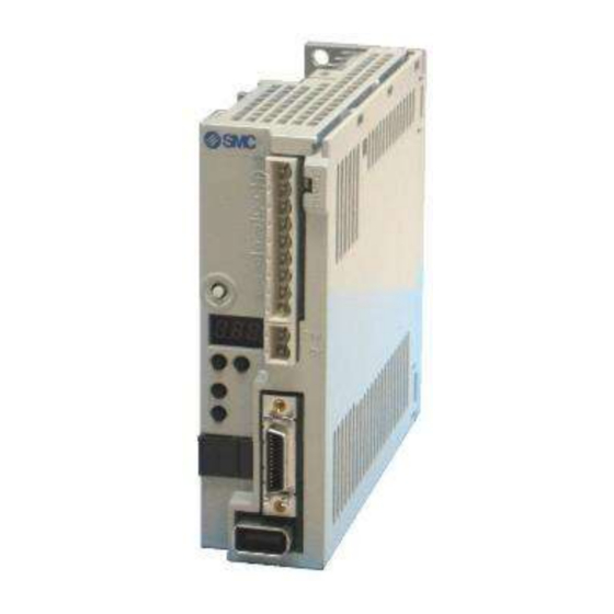
1. FUNCTIONS AND CONFIGURATION 1.7 Parts identification Detailed Name/Application explanation Serial number Main circuit power supply connector (CNP1) Section 3.1 Connect the input power supply/built-in regenerative Section 3.3 resistor/regenerative option/servo motor/earth. Charge lamp Lit to indicate that the main circuit is charged. While this lamp is lit, do not reconnect the cables. -
Page 48: Configuration Including Auxiliary Equipment
1. FUNCTIONS AND CONFIGURATION 1.8 Configuration including auxiliary equipment POINT Equipment other than the driver and servo motor are optional or recommended products. Driver Servo amplifier (Note) Main circuit power supply No-fuse breaker (NFB) or fuse Regenerative option Magnetic AUTO contactor (MC) Power factor... - Page 49 2. INSTALLATION 2. INSTALLATION ............................. 2 2.1 Installation direction and clearances ......................3 2.2 Keep out foreign materials ........................4 2.3 Cable stress ............................. 5 2.4 Inspection items ............................5 2.5 Parts having service lives ........................6 2 - 1...
-
Page 50: Installation
2. INSTALLATION 2. INSTALLATION WARNING Be sure to ground the driver to prevent electric shocks. Carry the products in a suitable way according to their weight. Stacking in excess of the limited number of product packages is not allowed. Do not hold the lead of the built-in regenerative resistor when transporting a driver. Install the equipment to incombustibles. -
Page 51: Installation Direction And Clearances
2. INSTALLATION 2.1 Installation direction and clearances The equipment must be installed in the specified direction. Otherwise, a fault may occur. CAUTION Leave specified clearances between the driver and control box inside walls or other equipment. A regenerative resistor is mounted on the back of this driver. The regenerative resistor causes a temperature rise of 100 relative to the ambient temperature. -
Page 52: Keep Out Foreign Materials
2. INSTALLATION (2) Installation of two or more drivers POINT LECSA□-□ series driver with any capacity can be mounted closely together. Leave a large clearance between the top of the driver and the internal surface of the control box, and install a cooling fan to prevent the internal temperature of the control box from exceeding the environmental conditions. -
Page 53: Cable Stress
2. INSTALLATION 2.3 Cable stress (1) The way of clamping the cable must be fully examined so that flexing stress and cable's own weight stress are not applied to the cable connection. (2) For use in any application where the servo motor moves, fix the cables (encoder, power supply, brake) with having some slack from the connector connection part of the servo motor to avoid putting stress on the connector connection part. -
Page 54: Parts Having Service Lives
2. INSTALLATION 2.5 Parts having service lives Service lives of the following parts are listed below. However, the service life varies depending on operating methods and environmental conditions. If any fault is found in the parts, they must be replaced immediately regardless of their service lives. - Page 55 3. SIGNALS AND WIRING 3. SIGNALS AND WIRING ..........................2 3.1 Input power supply circuit ........................3 3.2 I/O signal connection example ......................... 5 3.2.1 Position control mode ........................5 3.2.2 Internal speed control mode ......................7 3.2.3 Internal torque control mode ......................8 3.3 Explanation of power supply system ......................
-
Page 56: Signals And Wiring
3. SIGNALS AND WIRING 3. SIGNALS AND WIRING Any person who is involved in wiring should be fully competent to do the work. Before wiring, turn off the power and wait for 15 minutes or more until the charge lamp turns off. Otherwise, an electric shock may occur. In addition, always confirm from the front of the driver whether the charge lamp is off or not. -
Page 57: Input Power Supply Circuit
3. SIGNALS AND WIRING 3.1 Input power supply circuit Always connect a magnetic contactor (MC) between the main circuit power supply, and L and L of the driver to configure a circuit that shuts down the power on the driver's power supply side. If a magnetic contactor (MC) is not connected, continuous flow of a large current may cause a fire when the driver malfunctions. - Page 58 3. SIGNALS AND WIRING Note 1. The built-in regenerative resistor is provided for LECSA1-S3 and LECSA2-S4. (Factory-wired.) When using the regenerative option, refer to section 11.2. 2. For encoder cable, use of the option cable is recommended. Refer to section 11.1 for selection of the cable. 3.
-
Page 59: I/O Signal Connection Example
3. SIGNALS AND WIRING 3.2 I/O signal connection example 3.2.1 Position control mode Programmable logic 2m max. (Note 8) controller MT /ES (Note 13) Driver Servo amplifier (Note 7 ) (Note 7 ) (Note 2 ) 24VDC PLC power (Note 4, 10 ) DICOM RA 1 supply... - Page 60 3. SIGNALS AND WIRING Note 1. To prevent an electric shock, always connect the protective earth (PE) terminal (terminal marked ) of the driver to the protective earth (PE) of the control box. 2. Connect the diode in the correct direction. If it is connected reversely, the driver will be faulty and will not output signals, disabling the emergency stop and other protective circuits.
-
Page 61: Internal Speed Control Mode
3. SIGNALS AND WIRING 3.2.2 Internal speed control mode Driver Servo amplifier (Note 7) (Note 7) (Note 4, 9) (Note 2) 24VDC DICOM T rouble (Note 6) DOCOM RA 2 Speed reached (Note 3, 5) Forced stop (Note 9, 11) Servo-on RA 3 Ready... -
Page 62: Internal Torque Control Mode
3. SIGNALS AND WIRING 3.2.3 Internal torque control mode Driver Servo amplifier (Note 6) (Note 6) 24VDC (Note 4, 8) (Note 2) DICOM T rouble (Note 5) RA 1 DOCOM Ready (Note 8, 10) (Note 3) Forced stop Servo-on Electromagnetic (Note 8, 9) brake interlock Reset... -
Page 63: Explanation Of Power Supply System
3. SIGNALS AND WIRING 3.3 Explanation of power supply system 3.3.1 Signal explanations POINT For the layout of connector, refer to chapter 9 OUTLINE DRAWINGS. Connection target Abbreviation Description (application) Main circuit power Supply the 1-phase power 200 to 230VAC 50/60Hz to L and L supply 1) LECSA2-S1... - Page 64 3. SIGNALS AND WIRING (2) Timing chart Servo-on (SON) accepted (1 to 2s) Main circuit Control circuit Power supply Base circuit 10ms 10ms 95ms Servo-on (SON) 95ms Reset (RES) 10ms 10ms 10ms Ready (RD) No (ON) Trouble (ALM) Yes (OFF) Power-on timing chart (3) Forced stop Configure a circuit which interlocks with an external emergency stop switch in order...
-
Page 65: Cnp1 And Cnp2 Wiring Method
3. SIGNALS AND WIRING 3.3.3 CNP1 and CNP2 wiring method POINT Refer to section 11.5, for the wire sizes used for wiring. Use the supplied driver power supply connectors for wiring of CNP1 and CNP2. (1) Driver power supply connectors Driver Servo amplifier CNP1... - Page 66 3. SIGNALS AND WIRING (2) Termination of the wires (a) Solid wire The wire can be used just by stripping the sheath. Sheath Core Approx. 10mm (b) Twisted wire 1) Inserting the wires directly to the terminals Use the wire after stripping the sheath and twisting the core. At this time, take care to avoid a short caused by the loose wires of the core and the adjacent pole.
- Page 67 3. SIGNALS AND WIRING (3) Connection method (a) Inserting the wires directly to the terminals Insert the wire to the very end of the hole while pressing the button by a tool such as a small flat- blade screwdriver. Button Tools such as a small flat-blade screwdriver Twisted wire...
-
Page 68: Connectors And Signal Arrangements
3. SIGNALS AND WIRING 3.4 Connectors and signal arrangements POINT The pin configurations of the connectors are as viewed from the cable connector wiring section. Refer to (2) of this section for CN1 signal assignment. (1) Signal arrangement The driver front view shown is that of the LECSA2-S3 or less. Refer to chapter 9 OUTLINE DRAWINGS for the appearances and connector layouts of the other drivers. - Page 69 3. SIGNALS AND WIRING (2) CN1 signal assignment The signal assignment of connector changes with the control mode as indicated below; For the pins which are given parameter No. in the related parameter column, their signals can be changed using those parameters. (Note 2) I/O signals in control modes (Note 1) Related...
- Page 70 3. SIGNALS AND WIRING (3) Explanation of abbreviations Abbreviation Signal name Abbreviation Signal name Servo-on Trouble Reset In-position Proportion control Speed reached Forced stop Electromagnetic brake interlock Clear Limiting torque Forward rotation start Limiting speed Reverse rotation start Warning Forward rotation selection Zero speed Reverse rotation selection MTTR...
-
Page 71: Signal Explanations
3. SIGNALS AND WIRING 3.5 Signal explanations POINT For the positioning mode, refer to section 13.2.3. For the I/O interfaces (symbols in I/O division column in the table), refer to section 3.8.2. In the control mode field of the table P : Position control mode, S: Internal speed control mode, T: Internal torque control mode : Denotes that the signal may be used in the initial setting status. - Page 72 3. SIGNALS AND WIRING Control Connec- mode Device Symbol tor pin Functions/Applications division Internal The internal torque limit 2 (parameter No. PC14) becomes valid by turning DI-1 torque limit TL1 on. selection The forward torque limit (parameter No. PA11) and the reverse torque limit (parameter No.
- Page 73 3. SIGNALS AND WIRING Control Connec- mode Device Symbol tor pin Functions/Applications division <Internal speed control mode> Speed selection 1 DI-1 Used to select the command speed for operation. (Max. 8 speeds) (Note) Input device Speed command Internal speed command 0 (parameter No. PC05) Internal speed command 1 (parameter No.
- Page 74 3. SIGNALS AND WIRING Connec- Control mode Device Symbol tor pin Functions/Applications division Gain changing The values of the load to motor inertia moment ratio and the gains are DI-1 changed to the value set in parameter No. PB29 to PB34 by turning CDP Control change <Position/internal speed control change mode>...
- Page 75 3. SIGNALS AND WIRING Control Connec- mode Device Symbol tor pin Functions/Applications division Speed reached SA turns on when the servo motor speed has nearly reached the preset CN1-10 DO-1 speed. When the preset speed is 20r/min or less, SA always turns on. SA does not turn on even when the servo-on (SON) is turned off or the servo motor speed by the external force reaches the preset speed while both the forward rotation start (ST1) and the reverse rotation start (ST2)
- Page 76 3. SIGNALS AND WIRING (2) Input signals Control Connec- mode Signal Symbol Functions/Applications tor pin No. division Forward rotation CN1-23 Used to input command pulses. DI-2 pulse train CN1-25 In the open collector system (max. input frequency 200kpps) Reverse rotation CN1-22 Forward rotation pulse train across PP-DOCOM pulse train...
- Page 77 3. SIGNALS AND WIRING (4) Power supply Control Connec- mode Signal Symbol tor pin Functions/Applications division Digital I/F power DICOM CN1-1 Used to input 24VDC (200mA) for I/O interface. The power supply supply input capacity changes depending on the number of I/O interface points to be used.
-
Page 78: Detailed Description Of The Signals
3. SIGNALS AND WIRING 3.6 Detailed description of the signals POINT For the positioning mode, refer to section 13.2.4. 3.6.1 Position control mode POINT The noise immunity can be enhanced by setting parameter No. PA13 to "1 " when the frequency of the command input pulse is 500kpps or less and "2 "... - Page 79 3. SIGNALS AND WIRING 2) Differential line driver system Connect as shown below. Servo amplifier Driver Approx. (Note) Approx. Note. Pulse train input interface is comprised of a photo coupler. Therefore, it may be any malfunctions since the current is reduced when connect a resistance to a pulse train signal line.
- Page 80 3. SIGNALS AND WIRING (3) Ready (RD) Servo-on (SON) Alarm 10ms or less 100ms or less 10ms or less Ready (RD) (4) Torque limit If the torque limit is canceled during servo lock, the servo motor may suddenly CAUTION rotate according to position deviation in respect to the command position. (a) Torque limit and torque By setting parameter No.
-
Page 81: Internal Speed Control Mode
3. SIGNALS AND WIRING 3.6.2 Internal speed control mode (1) Internal speed command settings (a) Speed command and speed The servo motor operates at the speed set in the parameters. Up to 8 speeds can be set to the internal speed command. The following table indicates the rotation direction according to forward rotation start (ST1) and reverse rotation start (ST2) combination. - Page 82 3. SIGNALS AND WIRING POINT The servo-on (SON) can be set to turn on automatically by parameter No. PD01 (input signal automatic ON selection 1). The forward rotation stroke end (LSP) and the reverse rotation stroke end (LSN) switches as follows: Not assigned to the external input signals: automatically turns on regardless of the value set in parameter No.
- Page 83 3. SIGNALS AND WIRING (2) Speed reached (SA) SA turns on when the servo motor speed has nearly reached the speed set to the internal speed command. Internal speed Internal speed command 2 Set speed selection command 1 Forward rotation/ reverse rotation start (ST1/ST2) Servo motor speed...
-
Page 84: Internal Torque Control Mode
3. SIGNALS AND WIRING 3.6.3 Internal torque control mode (1) Internal torque command settings Torque is controlled by the internal torque command set in parameter No. PC12. If the internal torque command is small, the torque may vary when the actual speed reaches the speed limit value. - Page 85 3. SIGNALS AND WIRING (3) Speed limit (a) Speed limit value and speed The speed is limited to the values set in parameters No. PC05 to PC08 and PC31 to PC34 (Internal speed limit 0 to 7). When the servo motor speed reaches the speed limit value, the internal torque control may become instable.
- Page 86 3. SIGNALS AND WIRING (b) Speed selection 1 (SP1) and speed limit values At the initial condition, the speed limit values for the internal speed limits 0 and 1 can be selected using the speed selection 1 (SP1). (Note) Input device Speed limit value Internal speed limit 0 (parameter No.
-
Page 87: Position/Speed Control Change Mode
3. SIGNALS AND WIRING 3.6.4 Position/speed control change mode Set parameter No. PA01 to " 1 " to switch to the position/internal speed control change mode. (1) Control change (LOP) By using the control change (LOP), control mode can be switched between the position control and the internal speed control modes from an external contact. -
Page 88: Internal Speed/Internal Torque Control Change Mode
3. SIGNALS AND WIRING 3.6.5 Internal speed/internal torque control change mode Set No. PA01 to " 3 " to switch to the internal speed/internal torque control change mode. (1) Control change (LOP) By using the control change (LOP), the control mode can be switched between the internal speed control and the internal torque control mode from an external contact. -
Page 89: Internal Torque/Position Control Change Mode
3. SIGNALS AND WIRING 3.6.6 Internal torque/position control change mode Set parameter No. PA01 to " 5 " to switch to the internal torque/position control change mode. (1) Control change (LOP) By using the control change (LOP), the control mode can be switched between the internal torque control and the position control modes from an external contact. -
Page 90: Alarm Occurrence Timing Chart
3. SIGNALS AND WIRING 3.7 Alarm occurrence timing chart When an alarm has occurred, remove its cause, make sure that the operation signal is not being input, ensure safety, and reset the alarm before restarting CAUTION operation. As soon as an alarm occurs, turn off servo-on (SON) and power off. When an alarm occurs in the driver, the base circuit is shut off and the servo motor is coated to a stop. -
Page 91: Interfaces
3. SIGNALS AND WIRING 3.8 Interfaces 3.8.1 Internal connection diagram Servo amplifier Driver (Note 1) (Note 1) CP/CL CP/CL Approx. 5.6k SON SON SON ALM ALM RES RES RES (Note EM1 EM1 EM1 (Note LSP ST1 LSN ST2 MBR MBR Approx. -
Page 92: Detailed Description Of Interfaces
3. SIGNALS AND WIRING 3.8.2 Detailed description of interfaces This section provides the details of the I/O signal interfaces (refer to the I/O division in the table) given in section 3.5. Refer to this section and make connection with the external equipment. (1) Digital input interface DI-1 Give a signal with a relay or open collector transistor. - Page 93 3. SIGNALS AND WIRING (3) Pulse train input interface DI-2 Give a pulse train signal in the open collector system or differential line driver system. (a) Open collector system 1) Interface Driver Servo amplifier Max. input pulse 24VDC frequency 200kpps Approx.
- Page 94 3. SIGNALS AND WIRING 2) Input pulse condition tLH=tHL<0.1 s tc>0.35 s PP PG tF>3 s NP NG (4) Encoder output pulse DO-2 Encoder Z-phase pulse will correspond to the differential line driver system and the open collector system. (a) Open collector system Interface Max.
-
Page 95: Source I/O Interfaces
3. SIGNALS AND WIRING 2) Output pulse Servo motor CCW rotation Time cycle (T) is determined by the settings of parameter No.PA15 and PC13. 400 s or more 3.8.3 Source I/O interfaces In this driver, source type I/O interfaces can be used. In this case, all DI-1 input signals and DO-1 output signals are of source type. -
Page 96: Treatment Of Cable Shield External Conductor
3. SIGNALS AND WIRING 3.9 Treatment of cable shield external conductor In the case of the CN1 and CN2 connectors, securely connect the shielded external conductor of the cable to the ground plate as shown in this section and fix it to the connector shell. External conductor Sheath Core... -
Page 97: Connection Of Driver And Servo Motor
3. SIGNALS AND WIRING 3.10 Connection of driver and servo motor During power-on, do not open or close the motor power line. Otherwise, a CAUTION malfunction or faulty may occur. 3.10.1 Connection instructions Insulate the connections of the power supply terminals to prevent an electric WARNING shock. -
Page 98: Power Supply Cable Wiring Diagrams
3. SIGNALS AND WIRING 3.10.2 Power supply cable wiring diagrams (1) LE-□-□ series servo motor (a) When cable length is 10m or less 10m or less MR-PWS1CBL M-A1-L LE-CSM-□□□ MR-PWS1CBL M-A2-L MR-PWS1CBL M-A1-H Driver Servo amplifier Servo motor MR-PWS1CBL M-A2-H CNP1 AWG 19(red) AWG 19(white) -
Page 99: Servo Motor With A Lock
3. SIGNALS AND WIRING 3.11 Servo motor with a lock 3.11.1 Safety precautions Configure a lock operation circuit which interlocks with an external emergency stop switch. Contacts must be opened when ALM Contacts must be opened (Malfunction) or MBR (Electromagnetic with the EMG stop switch. -
Page 100: Timing Charts
3. SIGNALS AND WIRING 3.11.3 Timing charts (1) Servo-on (SON) command (from driver) ON/OFF Tb [ms] after the servo-on (SON) signal is switched off, the servo lock is released and the servo motor coasts. If the lock is made valid in the servo lock status, the lock life may be shorter. Therefore, when using the lock in a vertical lift application or the like, set Tb to about the same as the lock operation delay time to prevent a drop. - Page 101 3. SIGNALS AND WIRING (3) Alarm occurrence Dynamic brake Dynamic brake Electromagnetic brake Lock Servo motor speed Electromagnetic brake Lock (10ms) Base circuit (Note 1) Electromagnetic brake Lock operation operation delay time delay time (Note 2) ON Electromagnetic brake interlock (MBR) No (ON) Trouble (ALM) Yes (OFF)
-
Page 102: Wiring Diagrams (Le-□-□Series Servo Motor)
3. SIGNALS AND WIRING (5) Only main circuit power supply off (control circuit power supply remains on) Deceleration starts after the trouble (ALM) turns OFF. (Note 3) Dynamic brake Dynamic brake (10ms) Electromagnetic brake Lock Servo motor speed Electromagnetic brake Lock Electromagnetic brake sequence output Base circuit... - Page 103 3. SIGNALS AND WIRING (2) When cable length exceeds 10m When the cable length exceeds 10m, fabricate an extension cable as shown below on the customer side. In this case, the motor brake cable should be within 2m long. Refer to section 11.5 for the wire used for the extension cable. 2m or less MR-BKS1CBL2M-A1-L LE-CSB-□□□...
-
Page 104: Grounding
3. SIGNALS AND WIRING 3.12 Grounding Ground the driver and servo motor securely. WARNING To prevent an electric shock, always connect the protective earth (PE) terminal (terminal marked ) of the driver with the protective earth (PE) of the control box. The driver switches the power transistor on-off to supply power to the servo motor. - Page 105 4. PARAMETERS 4. PARAMETERS .............................. 2 4.1 Basic setting parameters (No. PA ) ....................3 4.1.1 Parameter list ............................ 3 4.1.2 Parameter write inhibit ........................4 4.1.3 Selection of control mode ........................5 4.1.4 Selection of regenerative option ......................6 4.1.5 Selection of the tough drive function ....................
-
Page 106: Parameters
4. PARAMETERS 4. PARAMETERS Never adjust or change the parameter values extremely as it will make operation CAUTION instable. POINT For the positioning mode, refer to section 13.7. Positioning mode is supported by driver with software version B0 or later. In this driver, the parameters are classified into the following groups on a function basis. -
Page 107: Parameters
4. PARAMETERS 4.1 Basic setting parameters (No. PA POINT For any parameter whose symbol is preceded by *, set the parameter value and switch power off once, then switch it on again to make that parameter setting valid. Never change parameters for manufacturer setting. 4.1.1 Parameter list Control mode Initial... -
Page 108: Parameter Write Inhibit
4. PARAMETERS 4.1.2 Parameter write inhibit Parameter Control mode Initial Setting Unit Internal Internal Symbol Name value range Position speed torque Refer to PA19 *BLK Parameter write inhibit 00Eh the text. POINT This parameter is made valid when power is switched off, then on after setting. In the factory setting, this driver allows to change all the setting parameters. -
Page 109: Selection Of Control Mode
4. PARAMETERS 4.1.3 Selection of control mode Parameter Control mode Initial Setting Unit Internal Internal value range Symbol Name Position speed torque Refer to PA01 *STY Control mode 000h the text. POINT This parameter is made valid when power is switched off, then on after setting. Select the control mode of the driver, and valid or invalid the one-touch tuning function. -
Page 110: Selection Of Regenerative Option
4. PARAMETERS Note 3. To set the maximum value for the each method, it is necessary to change the setting. Please refer 「13. POSITIONING MODE」. Note 4. The setup software (MR Configurator2 ) is necessary to control by the program method. Please prepare separately. -
Page 111: Selection Of The Tough Drive Function
4. PARAMETERS 4.1.5 Selection of the tough drive function Parameter Control mode Initial Setting Unit Internal Internal value range Symbol Name Position speed torque Refer to PA04 *AOP1 Tough drive function selection 000h the text. POINT This parameter is made valid when power is switched off, then on after setting. The tough drive function may not avoid the alarm depending on the conditions of the power supply and the load change. -
Page 112: Number Of Command Input Pulses Per Servo Motor Revolution
4. PARAMETERS 4.1.6 Number of command input pulses per servo motor revolution Parameter Control mode Initial Setting Unit Internal Internal Symbol Name value range Position speed torque 0 100 PA05 *FBP Number of command input pulses per revolution to 500 pulse/rev POINT This parameter is made valid when power is switched off, then on after setting. -
Page 113: Electronic Gear
4. PARAMETERS 4.1.7 Electronic gear Parameter Control mode Initial Setting Unit Internal Internal Symbol Name value range Position speed torque Electronic gear numerator 1 to PA06 (Command pulse multiplying factor numerator) 65535 Electronic gear denominator 1 to PA07 (Command pulse multiplying factor denominator) 65535 CAUTION Incorrect setting may cause unexpectedly fast rotation, resulting injury. - Page 114 4. PARAMETERS (a) For motion in increments of 10μm per pulse Machine specifications 1/n=Z =1/2 Ballscrew lead Pb 10 [mm] Reduction ratio: 1/n = Z = 1/2 Pb=10[mm] : Number of gear cogs on servo motor side Number of command input pulses : Number of gear cogs on axis side per revolution of servo motor: Number of command input pulses per revolution:...
- Page 115 4. PARAMETERS (2) Setting for use of QD75 The QD75 also has the following electronic gear parameters. Normally, the driver side electronic gear must also be set due to the restriction on the command pulse frequency (differential 1Mpulse/s, open collector 200kpulse/s).
- Page 116 4. PARAMETERS The following table indicates the electronic gear setting example (ballscrew lead = 10mm) when the QD75 is used in this way. Rated servo motor speed 3000r/min 2000r/min Open Differential Open Differential Input system collector line driver collector line driver Max.
-
Page 117: Auto Tuning
4. PARAMETERS 4.1.8 Auto tuning Parameter Control mode Initial Setting Unit Internal Internal Symbol Name value range Position speed torque Refer to PA08 Auto tuning mode 001h the text. PA09 Auto tuning response 1 to 16 POINT When executing one-touch tuning, the setting value of parameter No. PA08 is changed to "... -
Page 118: In-Position Range
4. PARAMETERS (2) Auto tuning response (parameter No. PA09) If the machine hunts or generates large gear sound, decrease the set value. To improve performance, e.g. shorten the settling time, increase the set value. Setting Response Low response High response 4.1.9 In-position range Parameter Control mode... -
Page 119: Torque Limit
4. PARAMETERS 4.1.10 Torque limit Parameter Control mode Initial Setting Unit Internal Internal Symbol Name value range Position speed torque PA11 Forward torque limit 0 to 100 PA12 Reverse torque limit 0 to 100 The torque generated by the servo motor can be limited. Refer to section 3.6.1 (4) and use these parameters. -
Page 120: Selection Of Command Input Pulse Form
4. PARAMETERS 4.1.11 Selection of command input pulse form Parameter Control mode Initial Setting Unit Internal Internal Symbol Name value range Position speed torque Refer to PA13 *PLSS Command input pulse form 000h the text. POINT This parameter is made valid when power is switched off, then on after setting. The noise immunity can be enhanced by setting parameter No. -
Page 121: Selection Of Servo Motor Rotation Direction
4. PARAMETERS 4.1.12 Selection of servo motor rotation direction Parameter Control mode Initial Setting Unit Internal Internal Symbol Name value range Position torque speed PA14 *POL Rotation direction selection POINT This parameter is made valid when power is switched off, then on after setting. Select servo motor rotation direction relative to the input pulse train. -
Page 122: Encoder Output Pulses
4. PARAMETERS 4.1.13 Encoder output pulses Parameter Control mode Initial Setting Unit Internal Internal Symbol Name value range Position speed torque 1 to pulse/ PA15 *ENR Encoder output pulses 4000 65535 1 to PA16 *ENR2 Encoder output pulse electronic gear 65535 POINT This parameter is made valid when power is switched off, then on after setting. - Page 123 4. PARAMETERS (2) For output division ratio setting Set parameter No. PC13 to " ". The number of pulses per servo motor revolution is divided by the set value. Resolution per servo motor revolution Output pulse= [pulse/rev] Setting valve For instance, when parameter No. PA15 is set to "8", the A/B-phase pulses actually output are as indicated below.
- Page 124 4. PARAMETERS (4) When multiplying A-phase/B-phase output pulses by the value of the electronic gear Set parameter No. PC13 to " ". The value resulted from multiplying the number of pulses per servo motor revolution by the value of the electronic gear becomes the output pulse.
-
Page 125: Gain/Filter Parameters (No. Pb )
4. PARAMETERS 4.2 Gain/filter parameters (No. PB POINT For any parameter whose symbol is preceded by *, set the parameter value and switch power off once, then switch it on again to make that parameter setting valid. Set any parameter with [Applied] written in the name column when using an advanced function. - Page 126 4. PARAMETERS Control mode No. Symbol Name Initial value Unit Internal Internal Position speed torque Gain changing vibration suppression control resonance frequency PB34 VRF2B 100.0 [Applied] setting PB35 For manufacturer setting PB36 PB37 PB38 NH3 4500 Machine resonance suppression filter 3 PB39 NHQ3 Notch shape selection 3 000h PB40...
-
Page 127: Detail List
4. PARAMETERS 4.2.2 Detail list Control mode Initial Setting No. Symbol Name and function Unit Internal Internal value range Position speed torque PB01 FILT Adaptive tuning mode (Adaptive filter ) 000h Refer to name and POINT function column. When executing one-touch tuning, the adaptive tuning mode starts automatically. - Page 128 4. PARAMETERS Control mode Initial Setting No. Symbol Name and function Unit Internal Internal value range Position speed torque PB02 VRFT Vibration suppression control tuning mode (Advanced vibration 000h Refer to suppression control) name and function POINT column. When using the vibration suppression control tuning mode (advanced vibration suppression control) and the one-touch tuning simultaneously, refer to section 7.2.4 (3).
- Page 129 4. PARAMETERS Control mode Initial Setting No. Symbol Name and function Unit Internal Internal value range Position speed torque PB03 PST Position command acceleration/deceleration time constant (Position smoothing) Used to set the time constant of a low-pass filter in response to the 20000 position command.
- Page 130 4. PARAMETERS Control mode Initial Setting No. Symbol Name and function Unit Internal Internal value range Position speed torque PB07 PG1 Model loop gain rad/s Set the response gain up to the target position. As the gain is increased, the track ability in response to the command 2000 is improved.
- Page 131 4. PARAMETERS Control mode Initial Setting No. Symbol Name and function Unit Internal Internal value range Position speed torque PB14 NHQ1 Notch shape selection 1 000h Refer to Used to select the machine resonance suppression filter 1. name and function column.
- Page 132 4. PARAMETERS Control mode Initial Setting No. Symbol Name and function Unit Internal Internal value range Position speed torque PB18 LPF Low-pass filter setting [Applied] 3141 rad/s Set the low-pass filter. Setting parameter No. PB23 (low-pass filter selection) to " "...
- Page 133 4. PARAMETERS Control mode Initial Setting No. Symbol Name and function Unit Internal Internal value range Position speed torque PB26 *CDP Gain changing selection [Applied] 000h Refer to Select the gain changing condition. (Refer to section 7.3.) name and function column.
- Page 134 4. PARAMETERS Control mode Initial Setting No. Symbol Name and function Unit Internal Internal value range Position speed torque PB34 VRF2B Gain changing vibration suppression control resonance frequency 100.0 setting [Applied] Set the resonance frequency for vibration suppression control when 100.0 the gain changing is valid.
-
Page 135: Position Smoothing
4. PARAMETERS 4.2.3 Position smoothing By setting the position command acceleration/deceleration time constant (parameter No. PB03), the servo motor is operated smoothly in response to a sudden position command. The following diagrams show the operation patterns of the servo motor in response to a position command when the position command acceleration/deceleration time constant is set. -
Page 136: Extension Setting Parameters (No. Pc )
4. PARAMETERS 4.3 Extension setting parameters (No. PC POINT For any parameter whose symbol is preceded by *, set the parameter value and switch power off once, then switch it on again to make that parameter setting valid. Set any parameter with [Applied] written in the name column when using an advanced function. - Page 137 4. PARAMETERS Control mode Initial Symbol Name Unit Internal Internal value Position speed torque PC33 Internal speed command 6 [Applied] 500 r/min Internal speed limit 6 [Applied] PC34 Internal speed command 7 [Applied] 800 r/min Internal speed limit 7 [Applied] For manufacturer setting PC35 000h...
-
Page 138: List Of Details
4. PARAMETERS 4.3.2 List of details Control mode Initial Setting No. Symbol Name and function Unit Internal Internal value range Position speed torque PC01 STA Acceleration time constant Used to set the acceleration time required for the servo motor to reach the rated speed from 0r/min in response to the internal speed 50000 commands 0 to 7. - Page 139 4. PARAMETERS Control mode Initial Setting No. Symbol Name and function Unit Internal Internal value range Position speed torque PC03 STC S-pattern acceleration/deceleration time constant Used to smooth start/stop of the servo motor. Set the time of the arc part for S-pattern acceleration/deceleration. 1000 Set "0"...
- Page 140 4. PARAMETERS Control mode Initial Setting No. Symbol Name and function Unit Internal Internal value range Position speed torque PC05 SC0 Internal speed command 0 0 to r/min Used to set speed 0 of internal speed commands. instan- taneous permi- Internal speed limit 0 ssible Used to set speed 0 of internal speed limits.
- Page 141 4. PARAMETERS Control mode Initial Setting No. Symbol Name and function Unit Internal Internal value range Position speed torque PC13 *ENRS Encoder output pulses selection 000h Refer to Use to select the encoder output pulse direction and the encoder the name output pulse setting.
- Page 142 4. PARAMETERS Control mode Initial Setting No. Symbol Name and function Unit Internal Internal value range Position speed torque PC22 *COP1 Function selection C-1 [Applied] 000h Refer to the name Select the encoder cable communication system. function field. Encoder cable communication system 0: Two-wire type 1: Four-wire type Incorrect setting will result in an encoder transmission...
- Page 143 4. PARAMETERS Control mode Initial Setting No. Symbol Name and function Unit Internal Internal value range Position speed torque PC26 ALDT Detailed setting of overload tough drive [Applied] Limits the maximum value of the output time delay of the in-position (INP) and zero speed (ZSP) while the overload tough drive.
- Page 144 4. PARAMETERS Control mode Initial Setting No. Symbol Name and function Unit Internal Internal value range Position speed torque PC32 SC5 Internal speed command 5 [Applied] 0 to r/min Used to set speed 5 of internal speed commands. instan- taneous permi- Internal speed limit 5 [Applied] Used to set speed 5 of internal speed limits.
-
Page 145: Alarm History Clear
4. PARAMETERS Control mode Initial Setting No. Symbol Name and function Unit Internal Internal value range Position speed torque PC53 000h PC54 000h PC55 000h PC56 000h PC57 000h PC58 000h PC59 For manufacturer setting 000h PC60 Do not change this value by any means. 000h PC61 000h... -
Page 146: Drive Recorder Function
4. PARAMETERS 4.3.4 Drive recorder function POINT Records the state transition when an alarm occurs. However, the previously recorded data is discarded. If another alarm occurs while an alarm is occurring, the state transition during that another alarm is not recorded. The drive recorder does not operate in the following situation. - Page 147 4. PARAMETERS Specify the alarm No. in parameter No. PC44 when operating the drive recorder with the specific alarm No. Parameter No. PC44 Specification of alarm No. : No specification (The optimum item is recorded according to the alarms that have occurred ea rlier and operating conditions.) 01 to FFh : Specification (The specified item is recorded when an alarm of the specified alarm No.
- Page 148 4. PARAMETERS (b) When the set value of parameter No. PC44 is other than " 00": The data to be recorded are as indicated in the following table. Digital CH data Sampling Measuring Corresponding Setting Analog CH data time length [ms] alarm No.
- Page 149 4. PARAMETERS Digital CH data Sampling Measuring Corresponding Setting Analog CH data time length [ms] alarm No. [ms] (64 points) (trigger) CH1 Servo motor speed [r/min] CH2 Torque [%] 56.8 3600 CH3 Effective load ratio [%] CH1 Servo motor speed [r/min] CH2 Torque [%] CH3 Droop pulses [pulse] (unit: 100 pulses) CH1 Servo motor speed [r/min]...
-
Page 150: I/O Setting Parameters (No. Pd )
4. PARAMETERS 4.4 I/O setting parameters (No. PD POINT For any parameter whose symbol is preceded by *, set the parameter value and switch power off once, then switch it on again to make that parameter setting valid. 4.4.1 Parameter list Control mode No. -
Page 151: List Of Details
4. PARAMETERS 4.4.2 List of details Control mode Initial Setting No. Symbol Name and function Unit Internal Internal value range Position speed torque PD01 *DIA1 Input signal automatic ON selection 1 0000h Refer to Select the input devices to be automatically turned ON. the name function field. - Page 152 4. PARAMETERS Control mode Initial Setting No. Symbol Name and function Unit Internal Internal value range Position speed torque ○ ○ PD02 *DI0 Input signal device selection 0(CN1-23,CN1-25) 262Dh Refer to Any input device can be assigned to the CN1-23 pin and CN1-25 the name pin(forward and reverse rotation pulse trains) For the position control mode, position/internal speed change mode or...
- Page 153 4. PARAMETERS Note 1. P: Position control mode S: Internal speed control mode T: Internal torque control mode CP: Positioning mode (Point table method) CL: Positioning mode (Program method) 2. For manufacturer setting. Never set this value. 3. It is valid in the positioning mode (Program method) only.
- Page 154 4. PARAMETERS Control mode Initial Setting No. Symbol Name and function Unit Internal Internal value range Position speed torque ○ ○ PD03 *DI1-1 Input signal device selection 1L (CN1-3) 0303h Refer to Any input signal can be assigned to the CN1-3 pin. the name Note that the setting digits and the signal that can be assigned vary depending on the control mode.
- Page 155 4. PARAMETERS Note 1. P: Position control mode S: Internal speed control mode T: Internal torque control mode CP:Positioning mode (Point table method) CL:Positioning mode (Program method) 2. For manufacturer setting. Never set this value. 3.It is valid in the positioning mode (Program method) only. 4.When operating temporarily without using EM1 such as at startup, etc., set the EM1 to automatic ON in parameter No.PD01.
- Page 156 4. PARAMETERS Control mode Initial Setting No. Symbol Name and function Unit Internal Internal value range Position speed torque PD04 *DI1-2 Input signal device selection 1H (CN1-3) 2003h Refer to Any input signal can be assigned to the CN1-3 pin. the name The devices that can be assigned and the setting method are the same as in parameter No.
- Page 157 4. PARAMETERS Control mode Initial Setting No. Symbol Name and function Unit Internal Internal value range Position speed torque PD09 *DI4-1 Input signal device selection 4L (CN1-6) 070Ah Refer to Any input signal can be assigned to the CN1-6 pin. the name The devices that can be assigned and the setting method are the same as in parameter No.
- Page 158 4. PARAMETERS Control mode Initial Setting No. Symbol Name and function Unit Internal Internal value range Position speed torque PD14 *DI6-2 Input signal device selection 6H (CN1-8) 0505h Refer to Any input signal can be assigned to the CN1-8 pin. the name The devices that can be assigned and the setting method are the same as in parameter No.
- Page 159 4. PARAMETERS Control mode Initial Setting No. Symbol Name and function Unit Internal Internal value range Position speed torque PD15 *DO1 Output signal device selection 1 (CN1-9) ○ ○ ○ 0003h Refer to Any output signal can be assigned to the CN1-9pin. ALM is assigned as the initial value.
- Page 160 4. PARAMETERS Control mode Initial Setting No. Symbol Name and function Unit Internal Internal value range Position speed torque PD16 *DO2 Output signal device selection 2 (CN1-10) 0004h Refer to Any output signal can be assigned to the CN1-10 pin. INP is assigned the name as the initial value.
- Page 161 4. PARAMETERS Control mode Initial Setting No. Symbol Name and function Unit Internal Internal value range Position speed torque PD20 *DOP1 Function selection D-1 0000h Refer to Select the stop processing at forward rotation stroke end the name (LSP)/reverse rotation stroke end (LSN) OFF, the base circuit status at reset (RES) ON and the operation during tough drive (MTTR).
-
Page 162: Using Forward/Reverse Rotation Stroke End To Change The Stopping Pattern
4. PARAMETERS Control mode Initial Setting No. Symbol Name and function Unit Internal Internal value range Position speed torque PD25 For manufacturer setting 0000h PD26 Do not change this value by any means. 0000h 4.4.3 Using forward/reverse rotation stroke end to change the stopping pattern The stopping pattern is factory-set to make a sudden stop when the forward/reverse rotation stroke end is made valid. - Page 163 5. DISPLAY AND OPERATION SECTIONS 5. DISPLAY AND OPERATION SECTIONS ..................... 2 5.1 Overview ..............................2 5.2 Display sequence ............................. 3 5.3 Status display ............................4 5.3.1 Display transition ..........................5 5.3.2 Display examples ..........................6 5.3.3 Status display list ..........................8 5.4 Diagnostic mode ............................
-
Page 164: Display And Operation Sections
5. DISPLAY AND OPERATION SECTIONS 5. DISPLAY AND OPERATION SECTIONS POINT Positioning mode is supported by driver with software version B0 or later. 5.1 Overview The LECSA□-□ driver has a display section (3-digit, 7-segment LED), operation section (4 pushbuttons) and a one-touch tuning button for driver status display, alarm display, parameter setting, etc. -
Page 165: Display Sequence
5. DISPLAY AND OPERATION SECTIONS 5.2 Display sequence Press the "MODE" button once to shift to the next display mode. Refer to section 5.3 and later for the description of the corresponding display mode. To refer to or set the gain/filter parameters, extension setting parameters and I/O setting parameters, make them valid with parameter No. -
Page 166: Status Display
5. DISPLAY AND OPERATION SECTIONS 5.3 Status display The servo status during operation is shown on the 3-digit, 7-segment LED display. Press the "UP" or the "DOWN" button to change the display data as desired. When the required data is selected, the corresponding symbol appears. -
Page 167: Display Transition
5. DISPLAY AND OPERATION SECTIONS 5.3.1 Display transition After selecting the status display mode by the "MODE" button, pressing the "UP" or the "DOWN" button changes the display as shown below. To Step No. Within one-revolution position Cumulativ e feedback pulses in pulse unit in pulse unit Within one-revolution position... -
Page 168: Display Examples
5. DISPLAY AND OPERATION SECTIONS 5.3.2 Display examples POINT The following is priority order of the status display when two or more decimal points need to be displayed. 1. Alarm occurrence, test operation 2. Negative values The following table lists display examples. Displayed data Item Status... - Page 169 5. DISPLAY AND OPERATION SECTIONS Displayed data Item Status Driver display Pulse unit 720000pulse 1000 pulse unit Cumulative feedback pulses Pulse unit Negative value is indicated by the lit decimal points in the upper two digits. -680000pulse 1000 pulse unit Negative value is indicated by the lit decimal points in the upper two digits.
-
Page 170: Status Display List
5. DISPLAY AND OPERATION SECTIONS 5.3.3 Status display list POINT Refer to appendix 4 for the measurement point. The following table lists the servo statuses that may be shown. Display Name Symbol Unit Description range Feedback pulses from the servo motor encoder are counted and Cumulative feedback pulse -999 to 999... - Page 171 5. DISPLAY AND OPERATION SECTIONS Display Name Symbol Unit Description range Current position in m The current position is displayed based on the machine home position -999 to 999 m unit (Note 1) being regarded as "0". Negative values are indicated by the lit decimal points in the upper two Current position in 1000 1000 -999 to 999...
-
Page 172: Diagnostic Mode
5. DISPLAY AND OPERATION SECTIONS 5.4 Diagnostic mode Name Display Description Not ready. Indicates that the driver is being initialized or an alarm has occurred. Sequence Ready. Indicates that the servo was switched on after completion of initialization and the driver is ready to operate. - Page 173 5. DISPLAY AND OPERATION SECTIONS Name Display Description Indicates the lower two digits of the system number of the software. Three digits are displayed by pressing Software version high the "SET" button. Series ID of the servo motor currently connected will be displayed by pressing the "SET"...
-
Page 174: Alarm Mode
5. DISPLAY AND OPERATION SECTIONS 5.5 Alarm mode The current alarm, the past alarm history, the number of tough drive, the number of drive recorder record times, and the parameter error No. are displayed. The lower 2 digits on the display indicate the alarm number that has occurred or the parameter number in error. - Page 175 5. DISPLAY AND OPERATION SECTIONS Name Display Description Indicates no occurrence of alarm 37 (parameter error). Indicates the parameter error No. If an error occurs in parameter No. PA12, "A12" is displayed while holding down the "SET" button. Parameter error No. Indicates the point table error No.
-
Page 176: Point Table Mode·············································································································
5. DISPLAY AND OPERATION SECTIONS 5.6 Point table mode In the positioning mode (point table method), the position data (target position), the servo motor speed, the acceleration time constant, the deceleration time constant, dwell, and the auxiliary function can be set. 5.6.1 Point table transition After selecting the point table mode with the "MODE"... -
Page 177: Point Table Mode Setting Screen Sequence
5. DISPLAY AND OPERATION SECTIONS 5.6.2 Point table mode setting screen sequence In the point table mode, pressing the "SET" button changes the screen as shown below. Press the "UP" or the "DOWN" button to move to the next screen. Position data (Target position) Servo motor speed... -
Page 178: Operation Example
5. DISPLAY AND OPERATION SECTIONS 5.6.3 Operation example POINT When the set value of a specified point table is changed and entered, the entered set value is displayed. The set value can be cancelled by pressing the "MODE" button for 2[s] or longer immediately after entering the value. Then, the previous set value is displayed. - Page 179 5. DISPLAY AND OPERATION SECTIONS (2) Setting of 4 or more digits The following example gives the operation procedure to change the position data (target position) of the point table No.1 to "123456". Press MODE three times. The point table No. is displayed. Press UP or DOWN to choose the point table No.1.
-
Page 180: Parameter Mode ············································································································
5. DISPLAY AND OPERATION SECTIONS 5.7 Parameter mode 5.7.1 Parameter mode transition After choosing the corresponding parameter mode with the "MODE" button, pressing the "UP" or the "DOWN" button changes the display as shown below. To status display mode MODE Gain/filter I/O setting Basic setting... -
Page 181: Operation Example
5. DISPLAY AND OPERATION SECTIONS 5.7.2 Operation example POINT When the set value of a specified parameter is changed and entered, the entered set value is displayed. The set value can be cancelled by pressing the "MODE" button for 2[s] or longer immediately after entering the value. Then, the previous set value is displayed. - Page 182 5. DISPLAY AND OPERATION SECTIONS (2) Parameter of 4 or more digits The following example gives the operation procedure to change the electronic gear numerator (command pulse multiplication numerator) (parameter No. PA06) to "12345". Press MODE three times. Press UP or DOWN to choose parameter No. PA06. Press SET once.
-
Page 183: External I/O Signal Display
5. DISPLAY AND OPERATION SECTIONS 5.8 External I/O signal display The ON/OFF states of the digital I/O signals connected to the driver can be confirmed. (1) Operation Call the display screen shown after power-on. Using the "MODE" button, show the diagnostic screen. Press UP once. - Page 184 5. DISPLAY AND OPERATION SECTIONS (a) Control modes and I/O signals (Note 2) Symbols of I/O signals in control modes Signal input/output Related Connector Pin No. (Note 1) I/O parameter CP/CL PD03 PD04 PD05 PD06 CR/SP1 SP1/SP1 SP1/CR PD07 PD08 LSP/ST1 ST1/RS2 RS2/LSP...
- Page 185 5. DISPLAY AND OPERATION SECTIONS (3) Display data at initial values (a) Position control mode CR(CN1-5) LSP(CN1-6) SON(CN1-4) LSN(CN1-7) RES(CN1-3) EM1(CN1-8) Input signals Lit: ON Extinguished: OFF Output signals OP(CN1-21) MBR(CN1-12) ALM(CN1-9) RD(CN1-11) INP(CN1-10) (b) Internal speed control mode SP1(CN1-5) ST1(CN1-6) SON(CN1-4) ST2(CN1-7)
-
Page 186: Output Signal (Do) Forced Output
5. DISPLAY AND OPERATION SECTIONS 5.9 Output signal (DO) forced output POINT When the servo system is used in a vertical lift application, turning on the electromagnetic brake interlock (MBR) with DO forced output after assigning it to connector CN1 will release the lock, causing a drop. Take drop preventive measures on the machine side. -
Page 187: Test Operation Mode
5. DISPLAY AND OPERATION SECTIONS 5.10 Test operation mode The test operation mode is designed to confirm servo operation. Do not use it for actual operation. CAUTION If any operational fault has occurred, stop the operation using the forced stop (EM1) signal. -
Page 188: Jog Operation
5. DISPLAY AND OPERATION SECTIONS 5.10.2 Jog operation POINT When performing jog operation, turn ON the forced stop (EM1), the forward rotation stroke end (LSP) and the reverse rotation stroke end (LSN). The forward rotation stroke end (LSP) and the reverse rotation stroke end (LSN) can be set to automatic ON by setting parameter No. -
Page 189: Positioning Operation
5. DISPLAY AND OPERATION SECTIONS 5.10.3 Positioning operation POINT Software(MR Configurator2 ) is required to perform positioning operation. Turn ON the forced stop (EM1) when performing positioning operation. During the positioning operation, the "UP" and the "DOWN" buttons are invalid. When using this function, external input signal operation will be disabled. - Page 190 5. DISPLAY AND OPERATION SECTIONS (1) Servo motor speed setting (a) Enter a new value into the "Motor speed" input field and press the enter key. (2) Acceleration/deceleration time constant setting (b) Enter a new value into the "Accel. / decal. time constant" input field and press the enter key. (3) Moving distance setting (c) Enter a new value into the "Move distance"...
-
Page 191: Motor-Less Operation
5. DISPLAY AND OPERATION SECTIONS (8) LSP/LSN (stroke end) automatic ON setting (h) Put a check mark in the check box to automatically turn ON LSP/LSN. After selecting the check box, the LSP and the LSN of external signal are ignored. (9) Automatic ON setting for the movement to the Z-phase signal (i) To move to the first Z-phase signal of the move distance + move direction, put a check mark in the check box. -
Page 192: Forced Tough Drive Operation
5. DISPLAY AND OPERATION SECTIONS 5.10.5 Forced tough drive operation POINT Execute forced tough drive operation after ten minutes of normal operation. The tough drive can be checked in advance by forcing the overload tough drive, even if the servo motor is in the normal status. - Page 193 6. GENERAL GAIN ADJUSTMENT 6. GENERAL GAIN ADJUSTMENT ........................2 6.1 One-touch tuning ............................2 6.1.1 One-touch tuning procedure ......................3 6.1.2 Display transition and operation procedure of the one-touch tuning..........4 6.1.3 Precautions for one-touch tuning ...................... 8 6.2 Gain adjustment methods ........................9 6.3 Auto tuning mode ...........................
- Page 194 6. GENERAL GAIN ADJUSTMENT 6. GENERAL GAIN ADJUSTMENT POINT When using in the internal torque control mode, gain adjustment is not necessary. When making gain adjustment, check that the machine is not operated at the maximum torque of the servo motor. The operation at the maximum torque or more may cause unexpected operations such as machine vibration, etc.
-
Page 195: General Gain Adjustment
6. GENERAL GAIN ADJUSTMENT 6.1.1 One-touch tuning procedure Use the following procedure to perform the one-touch tuning. START Refer to "Introduction" in this manual, and start up the Startup of system system. Rotate the servo motor by an external command device, Operation etc. -
Page 196: Display Transition And Operation Procedure Of The One-Touch Tuning
6. GENERAL GAIN ADJUSTMENT 6.1.2 Display transition and operation procedure of the one-touch tuning (1) Selection of the response mode Select the response mode of the one-touch tuning (three types) by the "UP" and the "DOWN" buttons. Response mode selection display Response mode for machines with low rigidity such as a belt drive. - Page 197 6. GENERAL GAIN ADJUSTMENT (2) Performing the one-touch tuning Select the response mode in (1), and press the "AUTO" button to start the one-touch tuning. During the one- touch adjustment The progress of the one-touch tuning is displayed from 0 to 100%. During the one-touch tuning, the decimal point is lit, moving from right to left.
- Page 198 6. GENERAL GAIN ADJUSTMENT (3) Cancelling the one-touch tuning Cancel symbol display In the one-touch tuning mode regardless of the item displayed, pressing "AUTO" button cancels the one-touch tuning mode. The cancel symbol display and error code "C00" (cancel during the adjustment) are At 2s intervals displayed alternately every 2s.
- Page 199 6. GENERAL GAIN ADJUSTMENT (5) At alarm occurrence During the one-touch tuning If some alarm occurs during the one-touch tuning, the one-touch tuning is canceled, and the alarm display is called. Alarm display (6) At warning occurrence During the one-touch tuning (a) If some warning occurs during the one-touch tuning, the alarm display is called, and the warning is displayed.
-
Page 200: Precautions For One-Touch Tuning
6. GENERAL GAIN ADJUSTMENT (7) Clearing the one-touch tuning POINT The one-touch tuning result can be reset to the initial value by the clear (CLr) mode and to the value before the adjustment by the back (bAC) mode. One-touch tuning clear mode selection (a) Pressing the "AUTO"... -
Page 201: Gain Adjustment Methods
6. GENERAL GAIN ADJUSTMENT 6.2 Gain adjustment methods The gain adjustment in this section can be made on a single driver. For the gain adjustment, refer to (3) in this section. One-touch tuning Estimation of load to Parameter No. Automatically set Gain adjustment method motor inertia moment Manually set parameters... - Page 202 6. GENERAL GAIN ADJUSTMENT (3) Adjustment sequence and mode usage START Usage This driver enables the auto Operation tuning mode 1 in the initial status. (Refer to section 6.3.1.) Perform the one-touch tuning? Use the one-touch tuning button (AUTO) to make the adjustment.
-
Page 203: Auto Tuning Mode
6. GENERAL GAIN ADJUSTMENT 6.3 Auto tuning mode 6.3.1 Overview The driver has a real-time auto tuning function which estimates the machine characteristic (load to motor inertia moment ratio) in real time and automatically sets the optimum gains according to that value. This function permits ease of gain adjustment of the driver. -
Page 204: Auto Tuning Mode 1 Operation
6. GENERAL GAIN ADJUSTMENT 6.3.2 Auto tuning mode 1 operation The function block diagram of real-time auto tuning is shown below. Load to motor inertia moment Automatic setting Encoder Loop gains Command Current PG1,PG2,VG2 control Servo motor Current feedback Real-time auto Position/speed Set 0 or 1 to turn on. -
Page 205: Adjustment Procedure By Auto Tuning
6. GENERAL GAIN ADJUSTMENT 6.3.3 Adjustment procedure by auto tuning Since auto tuning is made valid before shipment from the factory, simply running the servo motor automatically sets the optimum gains that match the machine. Merely changing the response level setting value as required completes the adjustment. -
Page 206: Response Level Setting In Auto Tuning Mode 1
6. GENERAL GAIN ADJUSTMENT 6.3.4 Response level setting in auto tuning mode 1 Set the response (The first digit of parameter No. PA09) of the whole servo system. As the response level setting is increased, the track ability and settling time for a command decreases, but a too high response level will generate vibration. -
Page 207: 2-Gain Adjustment Mode
6. GENERAL GAIN ADJUSTMENT 6.4 2-gain adjustment mode POINT Use this mode to improve the response level after the one-touch tuning. Use parameters No. PA09 or PB07 for fine adjustment. Use the 2-gain adjustment mode for fine adjustment of the response level setting and the model loop gain. (1) Parameters (a) Automatically adjusted parameters The following parameters are automatically adjusted by the auto tuning 1. -
Page 208: Manual Mode
6. GENERAL GAIN ADJUSTMENT 6.5 Manual mode If the adjustment made by the auto tuning mode 1 and 2-gain adjustment mode is not satisfactory, adjust the load to motor inertia moment and all gains in the manual mode. POINT Use this mode if the estimation of the load to motor inertia moment ratio is not the normal value. - Page 209 6. GENERAL GAIN ADJUSTMENT (c) Adjustment description 1) Speed loop gain (VG2: parameter No. PB09) This parameter determines the response level of the speed control loop. Increasing this value enhances response but a too high value will make the mechanical system liable to vibrate. The actual response frequency of the speed loop is as indicated in the following expression.
- Page 210 6. GENERAL GAIN ADJUSTMENT (b) Adjustment procedure Step Operation Description Brief-adjust with auto tuning. Refer to section 6.3.3. Change the setting of auto tuning to the manual mode (Parameter No.PA08: 003). Set an estimated value to the load to motor inertia moment ratio. (If the estimate value with auto tuning is correct, setting change is not required.) Set a slightly smaller value to the model loop gain and the position loop gain.
- Page 211 7. SPECIAL ADJUSTMENT FUNCTIONS 7. SPECIAL ADJUSTMENT FUNCTIONS ......................2 7.1 Tough drive function..........................2 7.1.1 Overload tough drive function ......................2 7.1.2 Vibration tough drive function ......................3 7.1.3 Instantaneous power failure tough drive function ................5 7.2 Machine resonance suppression function....................7 7.2.1 Function block diagram ........................
-
Page 212: Special Adjustment Functions
7. SPECIAL ADJUSTMENT FUNCTIONS 7. SPECIAL ADJUSTMENT FUNCTIONS 7.1 Tough drive function POINT Enable or disable the tough drive function by parameter No.PA04 (tough drive function selection). (Refer to section 4.1.5.) The tough drive function continues the operation not to stop the machine in such situation when normally an alarm is activated. -
Page 213: Vibration Tough Drive Function
7. SPECIAL ADJUSTMENT FUNCTIONS However, the overload tough drive function is not effective in the following cases. (1) When the effective load ratio temporarily exceeds 200%. (2) When the load increases at a stop such as a detent torque of a vertical lift. Load fluctuation Load fluctuation Overload tough drive start... - Page 214 7. SPECIAL ADJUSTMENT FUNCTIONS The vibration tough drive function activates when a detected frequency is within the range of 30% in relation to the setting value of parameters No. PB13 (machine resonance suppression filter 1) and No. PB15 (machine resonance suppression filter 2). The detection level of the vibration tough drive function can be set by parameter No.
-
Page 215: Instantaneous Power Failure Tough Drive Function
7. SPECIAL ADJUSTMENT FUNCTIONS 7.1.3 Instantaneous power failure tough drive function During the instantaneous power failure tough drive, the torque may be limited due to the load conditions or the set value of parameter No. PC28 (detailed setting of instantaneous power failure tough drive). CAUTION The immunity to instantaneous power failures is increased by the instantaneous power failure tough drive function. - Page 216 7. SPECIAL ADJUSTMENT FUNCTIONS (2) When an undervoltage occurs during the instantaneous main circuit power failure Instantaneous power failure time of the main circuit power supply Main circuit power supply Parameter No. PC28 Bus voltage Undervoltage level (158VDC) An undervoltage alarm (10.2) is generated if the bus voltage reduces at the undervoltage level or lower.
-
Page 217: Machine Resonance Suppression Function
7. SPECIAL ADJUSTMENT FUNCTIONS 7.2 Machine resonance suppression function POINT The functions given in this section are not generally required to use. Use these functions when the machine status is not satisfactory after making adjustment in the methods given in chapter 6. If a mechanical system has a natural resonance point, increasing the servo system response level may cause the mechanical system to produce resonance (vibration or unusual noise) at that resonance frequency. -
Page 218: Adaptive Filter
7. SPECIAL ADJUSTMENT FUNCTIONS 7.2.2 Adaptive filter (1) Function The adaptive filter (adaptive tuning) sets the filter characteristics automatically with the one-touch tuning, and suppresses vibrations of the mechanical system. Since the filter characteristics (frequency, depth) are set automatically, you need not be conscious of the resonance frequency of a mechanical system. Machine resonance point Machine resonance point Mechanical... - Page 219 7. SPECIAL ADJUSTMENT FUNCTIONS 7.2.3 Machine resonance suppression filter (1) Function The machine resonance suppression filter is a filter function (notch filter) which can suppress the resonance of the mechanical system by decreasing the gain of the specific frequency. You can set the gain decreasing frequency (notch frequency), gain decreasing depth and width.
-
Page 220: Machine Resonance Suppression Filter
7. SPECIAL ADJUSTMENT FUNCTIONS (2) Parameters Set the machine resonance suppression filters by the following parameters: Parameters to be set Item Note Notch frequency Notch depth and width The set values are valid when "manual mode" is Machine resonance Parameter No. PB13 Parameter No. -
Page 221: Advanced Vibration Suppression Control
7. SPECIAL ADJUSTMENT FUNCTIONS 7.2.4 Advanced vibration suppression control (1) Operation Vibration suppression control is used to further suppress machine end vibration, such as workpiece end vibration and base shake. The motor side operation is adjusted for positioning so that the machine does not shake. - Page 222 7. SPECIAL ADJUSTMENT FUNCTIONS POINT When executing the vibration suppression control tuning mode (advanced vibration suppression control), follow the procedures of (3) in this section. This function is valid when the auto tuning mode (parameter No. PA08) is set to manual mode ("...
- Page 223 7. SPECIAL ADJUSTMENT FUNCTIONS (3) Vibration suppression control tuning mode procedure START Operation Is the target response reached? Execute one-touch tuning Has vibration of workpiece end/device increased? Stop operation. Set the auto tuning mode to the manual mode (parameter No. PA08: 003).
- Page 224 7. SPECIAL ADJUSTMENT FUNCTIONS (4) Vibration suppression control manual mode Vibration suppression control can be set manually by setting the vibration suppression control vibration frequency (parameter No. PB19) and the vibration suppression control resonance frequency (parameter No. PB20) after measuring work-end vibration and device shake using an external measuring instrument. (a) When a vibration peak can be measured using an external measuring instrument Gain characteristic 100Hz...
-
Page 225: Applications
7. SPECIAL ADJUSTMENT FUNCTIONS 7.2.5 Low-pass filter (1) Function When a ballscrew or the like is used, resonance of high frequency may occur as the response level of the servo system is increased. To prevent this, the low-pass filter for a torque command is set valid. In the initial setting, the filter frequency of the low-pass filter is automatically adjusted to the value in the following expression. - Page 226 7. SPECIAL ADJUSTMENT FUNCTIONS 7.3.2 Function block diagram The valid loop gains PG2, VG2, VIC, GD2, VRF1 and VRF2 of the actual loop are changed according to the conditions selected by gain changing selection CDP (parameter No. PB26) and gain changing condition CDL (parameter No.
-
Page 227: Parameters
7. SPECIAL ADJUSTMENT FUNCTIONS 7.3.3 Parameters When using the gain changing function, always set parameter No. PA08 (auto tuning mode) to " 3" to select manual mode in the auto tuning mode. The gain changing function cannot be used in the auto tuning mode. - Page 228 7. SPECIAL ADJUSTMENT FUNCTIONS (4) Gain changing selection (parameter No. PB26) This parameter is used to set the gain changing condition. Select the changing condition in the first and second digits. If "1" is set in the first digit, the gain can be changed by the gain changing (CDP) input device. The gain changing (CDP) can be assigned to CN1-pin 3 to CN1-pin 8 using parameters No.
-
Page 229: Gain Changing Operation
7. SPECIAL ADJUSTMENT FUNCTIONS 7.3.4 Gain changing operation The operation is explained with setting examples below: (1) When gain changing by an input device (CDP) is selected: (a) Setting Parameter No. Abbreviation Name Setting Unit Multiplier PB06 Load to motor inertia moment ratio ( 1) PB07 Model loop gain... - Page 230 7. SPECIAL ADJUSTMENT FUNCTIONS (2) When gain changing by droop pulses is selected: In this case, gain changing vibration suppression control cannot be used. (a) Setting Parameter No. Abbreviation Name Setting Unit Multiplier PB06 Load to motor inertia moment ratio ( 1) PB07 Model loop gain...
- Page 231 8. TROUBLESHOOTING 8. TROUBLESHOOTING........................... 2 8.1 Alarms and warning list ..........................2 8.2 Remedies for alarms ..........................4 8.3 Remedies for warnings .......................... 27 8 - 1...
- Page 232 8. TROUBLESHOOTING 8. TROUBLESHOOTING POINT As soon as an alarm occurs, turn off servo-on (SON) and the main circuit power supply. If an alarm/warning has occurred, refer to this chapter and remove its cause. 8.1 Alarms and warning list When a fault occurs during the operation, the corresponding alarm or warning is displayed. If any alarm or warning has occurred, refer to section 8.2 or 8.3 and take the appropriate action.
- Page 233 8. TROUBLESHOOTING 3-digit, 7-segment The servo motor stops Name /does not stop. display Stops A.90 Home positioning incomplete warning Does not stop A.91 Driver overheat warning Stops A.96 Home position setting error Does not stop A.97 Program operation disabled Stops (Note 2) A.98 Software limit warning Stops (Note 2)
- Page 234 8. TROUBLESHOOTING 8.2 Remedies for alarms When any alarm has occurred, eliminate its cause, ensure safety, then reset the alarm, and restart operation. Otherwise, injury may occur. CAUTION As soon as an alarm occurs, turn off servo-on (SON) and the main circuit power supply.
- Page 235 8. TROUBLESHOOTING Alarm No.: A.10 Name: Undervoltage Control circuit power supply voltage dropped. Description Main circuit power supply voltage dropped. Main circuit power supply is turned off. Detailed Detailed Cause Checking method Result Action display Name 10.1 Control 1) Control circuit power Check the control The connector is Connect correctly.
- Page 236 8. TROUBLESHOOTING Alarm No.: A.12 Name: Memory error 1 (RAM) Description Driver internal part (CPU) is faulty. Detailed Detailed Cause Checking method Result Action display Name CPU built-in 1) Faulty parts in the driver Remove all cables Alarm occurs. Replace the driver. 12.1 RAM fault except for the control...
- Page 237 8. TROUBLESHOOTING Alarm No.: A.16 Name: Encoder initial communication error 1 Description Communication error occurred between the encoder and the driver. Detailed Detailed Cause Checking method Result Action display Name 16.0 Encoder 1) Encoder cable faulty Check the shield Error in the shield. Repair the cable.
- Page 238 8. TROUBLESHOOTING Alarm No.: A.16 Name: Encoder initial communication error 1 Description Communication error occurred between the encoder and the driver. Detailed Detailed Cause Checking method Result Action display Name 16.5 Encoder Encoder cable faulty Check the shield Error in the shield. Repair the cable.
- Page 239 8. TROUBLESHOOTING Alarm No.: A.19 Name: Memory error 3 (Flash ROM) Description Driver internal part (Flash-ROM) is faulty. Detailed Detailed Cause Checking method Result Action display Name 19.1 Flash-ROM 1) Flash-ROM fault Remove all cables Alarm occurs. Replace the driver. error1 except for the control circuit power supply...
- Page 240 8. TROUBLESHOOTING Alarm No.: A.20 Name: Encoder normal communication error 1 Description Communication error occurred between the encoder and the driver. Detailed Detailed Cause Checking method Result Action display Name 20.1 Encoder 1) Encoder cable is Check if the encoder Disconnected.
- Page 241 8. TROUBLESHOOTING Alarm No.: A.24 Name: Main circuit error Ground fault occurred in the servo motor power cables. Description Ground fault occurred in the servo motor Detailed Detailed Cause Checking method Result Action display Name 24.1 Ground fault 1) Driver fault Alarm occurs even if Alarm occurs.
- Page 242 8. TROUBLESHOOTING Alarm No.: A.30 Name: Regenerative error Permissible regenerative power of the built-in regenerative resistor or the regenerative option is exceeded. Description Regenerative transistor faulty in the driver. Detailed Detailed Cause Checking method Result Action display Name 30.1 Regenerative 1) Incorrect setting of the Check the built-in The set value is...
- Page 243 8. TROUBLESHOOTING Alarm No.: A.31 Name: Overspeed Description Servo motor speed has exceeded the instantaneous permissible speed. Detailed Detailed Cause Checking method Result Action display Name 31.1 Motor speed 1) Command speed is high. Check if the command The command Check the operation error speed exceeds the...
- Page 244 8. TROUBLESHOOTING Alarm No.: A.32 Name: Overcurrent Description The flowed current is higher than the permissible current of the driver. Detailed Detailed Cause Checking method Result Action display Name 32.1 Overcurrent Driver fault Check if the alarm Alarm occurs. Replace the driver. occurs even if the Alarm does not Check 2).
- Page 245 8. TROUBLESHOOTING Alarm No.: A.32 Name: Overcurrent Description The flowed current is higher than the permissible current of the driver. Detailed Detailed Cause Checking method Result Action display Name 32.2 Overcurrent 1) High servo gain Check if the oscillation Oscillation occurs. Decrease the speed loop occurs.
- Page 246 8. TROUBLESHOOTING Alarm No.: A.33 Name: Overvoltage Description The value of the status display Pn (bus voltage) is "5" (overvoltage). Detailed Detailed Cause Checking method Result Action display Name 33.1 Main circuit 1) The regenerative option is Check the set value of Incorrect setting.
- Page 247 8. TROUBLESHOOTING Alarm No.: A.35 Name: Command frequency error Description Input command frequency is too high. Detailed Detailed Cause Checking method Result Action display Name Check the speed 35.1 Command 1) Command frequency is 1.5 The set value of the Check operation pattern.
- Page 248 8. TROUBLESHOOTING Alarm No.: A.37 Name: Parameter error Description Parameter setting is incorrect. Detailed Detailed Cause Checking method Result Action display Name 37.3 Point table 1) Point table is set outside Check the set value Outside the setting Correct the value within setting range the setting range.
- Page 249 8. TROUBLESHOOTING Alarm No.: A.45 Name: Main circuit device overheat Description Overheat in driver. Detailed Detailed Cause Checking method Result Action display Name 45.1 Board 1) Ambient temperature is Check if the ambient Ambient Lower the ambient temperature over 55 . temperature is 55 temperature is over temperature.
- Page 250 8. TROUBLESHOOTING Alarm No.: A.50 Name: Overload 1 Description Load exceeded overload protection characteristic of driver. Detailed Detailed Cause Checking method Result Action display Name 50.1 Overload 1) Lock operates. Check if the lock does Operates Check the wiring. thermal 1 not operate during Does not operate.
- Page 251 8. TROUBLESHOOTING Alarm No.: A.50 Name: Overload 1 Description Load exceeded overload protection characteristic of driver. Detailed Detailed Cause Checking method Result Action display Name 50.4 Overload 1) Lock operates. Check if the lock does Operated. Check the wiring. thermal 1 not operate during Not operated.
- Page 252 8. TROUBLESHOOTING Alarm No.: A.51 Name: Overload 2 Description Machine collision or the like caused continuous flow of the maximum output current for a few seconds. Detailed Detailed Cause Checking method Result Action display Name 51.1 Overload 1) Power cables breakage Check the power An error is found.
- Page 253 8. TROUBLESHOOTING Alarm No.: A.52 Name: Error excessive Description The droop pulse between the command position and the current position exceeds the alarm level. Detailed Detailed Cause Checking method Result Action display Name 52.3 Droop 1) Servo motor power cables Check the wiring.
- Page 254 8. TROUBLESHOOTING Alarm No.: A.52 Name: Error excessive Description The droop pulse between the command position and current position exceeds the alarm level. Detailed Detailed Cause Checking method Result Action display Name 52.3 Droop 12) Servo motor is rotated by Measure the actual The servo motor is Check the machine.
- Page 255 8. TROUBLESHOOTING Alarm No.: A.8E Name: USB communication error USB communication error occurred between the driver and the communication device (e.g. personal Description computer). Detailed Detailed Cause Checking method Result Action display Name 8E.1 Communication cable fault Check if the alarm Alarm does not Replace the USB cable.
- Page 256 8. TROUBLESHOOTING Alarm No.: 888 (Note) Name: Watchdog Description CPU or part is faulty. Detailed Detailed Cause Checking method Result Action display Name 1) Fault of parts in the driver Replace the driver. Note. At power-on, "888" appears instantaneously, but it is not an error. 8 - 26...
- Page 257 8. TROUBLESHOOTING 8.3 Remedies for warnings POINT When any of the following alarms has occurred, do not resume operation by switching power of the driver OFF/ON repeatedly. The driver and servo motor may become faulty. If the power of the driver is switched OFF/ON during the alarms, allow more than 30 minutes for cooling before resuming operation.
- Page 258 8. TROUBLESHOOTING Alarm No.: A.96 Name: Home position setting error The servo motor stops. Incorrectly finished after home position return operation. Warning contents Detailed Detailed Cause Checking method Result Action display Name 96.1 In-position 1) Droop pulses remaining Check the number of In-position range or Remove the cause of not reached...
- Page 259 8. TROUBLESHOOTING Alarm No.: A.98 Name: Software limit warning The servo motor stops. Description The current position reached the software stroke limit (set in the parameter No. PE16 to PE19). Detailed Detailed Cause Checking method Result Action display Name 98.1 Reached the 1) Software limit was set Check the set value of...
- Page 260 8. TROUBLESHOOTING Alarm No.: A.E0 Name: Excessive regenerative warning The operation does not stop. There is a possibility that regenerative power may exceed the permissible regenerative power of the built- Warning contents in regenerative resistor or the regenerative option. Detailed Detailed Cause Checking method...
- Page 261 8. TROUBLESHOOTING Alarm No.: A.E6 Name: Servo forced stop warning The operation stops. Warning contents The forced stop signal is turned OFF. Detailed Detailed Cause Checking method Result Action display Name E6.1 Servo forced 1) Forced stop (EM1) is Check the forced stop Ensure safety and turn ON stop warning turned OFF.
- Page 262 8. TROUBLESHOOTING Alarm No.: A.E9 Name: Main circuit off warning The operation does not stop. Servo-on (SON) was switched on when the main circuit power is off. Warning contents The bus voltage decreased while the servo motor speed operates at 50r/min or slower. Detailed Detailed Cause...
- Page 263 8. TROUBLESHOOTING Alarm No.: A.F0 Name: Tough drive warning The operation does not stop. Warning contents Switched to "during tough drive" status. Detailed Detailed Cause Checking method Result Action display Name F0.1 Instantaneous 1) An instantaneous power Check the main circuit power supply. power failure failure in the main circuit tough drive...
- Page 264 9. OUTLINE DRAWINGS 9. OUTLINE DRAWINGS ..........................2 9.1 Driver ................................ 2 9.2 Connector ..............................4 9 - 1...
- Page 265 9. OUTLINE DRAWINGS 9. OUTLINE DRAWINGS 9.1 Driver (1) LECSA□-S1・LECSA□-S3 [Unit: mm] LECSA□-S3 Mass: 0.6[kg] (1.32[lb]) Terminal layout CNP1 CNP2 Mounting screw Screw size: M5 Tightening torque: 3.24[N m] (28.7[lb in]) 9 - 2...
- Page 266 9. OUTLINE DRAWINGS (2) LECSA□-S4 [Unit: mm] Mass: 0.7[kg] (1.54[lb]) Terminal layout CNP1 CNP2 Mounting screw Screw size: M5 Tightening torque: 3.24[N m] (28.7[lb in]) 9 - 3...
- Page 267 9. OUTLINE DRAWINGS 9.2 Connector (1) Miniature delta ribbon (MDR) system (Sumitomo 3M Limited) (a) One-touch lock type Applicable wire size: AWG24~30 [Unit: mm] Logo etc, are indicated here. 12.7 Each type of dimension Connector Shell kit 10126-3000PE 10326-52F0-008 25.8 37.2 14.0 10.0...
- Page 268 9. OUTLINE DRAWINGS (2) SCR connector system (Sumitomo 3M Limited) Receptacle : 36210-0100PL Shell kit : 36310-3200-008 [Unit: mm] 39.5 34.8 9 - 5...
- Page 269 10. CHARACTERISTICS 10. CHARACTERISTICS ........................... 2 10.1 Overload protection characteristics ......................2 10.2 Power supply capacity and generated loss ................... 3 10.3 Dynamic brake characteristics ......................5 10.3.1 Dynamic brake operation ........................ 5 10.3.2 The dynamic brake at the load inertia moment ................6 10.4 Cable flexing life .............................
-
Page 270: Characteristics
10. CHARACTERISTICS 10. CHARACTERISTICS 10.1 Overload protection characteristics An electronic thermal relay is built in the driver to protect the servo motor, driver and servo motor power lines from overloads. Overload 1 alarm (50. ) occurs if overload operation that exceeds the electronic thermal relay protection curve shown in Figs 10.1. -
Page 271: Power Supply Capacity And Generated Loss
10. CHARACTERISTICS 10.2 Power supply capacity and generated loss (1) Amount of heat generated by the driver Table 10.1 indicates drivers' power supply capacities and losses generated under rated load. For thermal design of an enclosure, use the values in Table 10.1 in consideration for the worst operating conditions. The actual amount of generated heat will be intermediate between values at rated torque and servo off according to the duty used during operation. - Page 272 10. CHARACTERISTICS (Outside) (Inside) Air flow Fig. 10.2 Temperature distribution in enclosure When air flows along the outer wall of the enclosure, effective heat exchange will be possible, because the temperature slope inside and outside the enclosure will be steeper. 10 - 4...
-
Page 273: Dynamic Brake Characteristics
10. CHARACTERISTICS 10.3 Dynamic brake characteristics POINT The dynamic brake is operated when an alarm occurs, a servo forced stop warning occurs, or the power turns off. The dynamic break is a function for emergency stops. Do not use this function for normal stops. The criteria for the number of times the dynamic break is used is 1000 times, in the condition that the machine with recommended load to motor inertia moment ratio or less, stops from the rated speed in a frequency of once per... - Page 274 10. CHARACTERISTICS (2) Dynamic brake time constant The following shows necessary dynamic brake time constant for the equations (10.2). 1000 2000 3000 4000 4500 Speed [r/min] LE-S1-□,LE-S2-□ LE-S3-□,LE-S4-□ series 10.3.2 The dynamic brake at the load inertia moment Use the dynamic brake under the load to motor inertia moment ratio indicated in the following table. If the load to motor inertia moment is higher than this value, the built-in dynamic brake may burn.
-
Page 275: Cable Flexing Life
10. CHARACTERISTICS 10.4 Cable flexing life The flexing life of the cables is shown below. This graph calculated values. Since they are not guaranteed values, provide a little allowance for these values. The minimum bending radius : Min. 45mm. 1 10 5 10 1 10 a : Long flex life encoder cable... - Page 276 OPTIONS AND AUXILIARY EQUIPMENT 11. OPTIONS AND AUXILIARY EQUIPMENT....................2 11.1 Cable/connector sets ..........................2 11.1.1 Combinations of cable/connector sets .................... 2 11.1.2 Encoder cable ..........................5 11.1.3 Motor cable ............................7 11.1.4 Lock cables............................8 11.2 Regenerative options ..........................9 11.3 Setup software(MR Configurator2 ) ....................
-
Page 277: Options And Auxiliary Equipment
11. OPTIONS AND AUXILIARY EQUIPMENT 11. OPTIONS AND AUXILIARY EQUIPMENT Before connecting options and peripheral equipment, turn off the power and wait for 15 minutes or more until the charge lamp turns off. Otherwise, an electric shock WARNING may occur. In addition, always confirm from the front of the driver whether the charge lamp is off or not. - Page 278 11. OPTIONS AND AUXILIARY EQUIPMENT Product Model Description Application CN1 connector LE-CSNA Connector: 10126-3000PE Shell kit: 10326-52F0-008 (Sumitomo Limited equivalent) Motor cable LE-CSM-S□A IP65 Power supply connector Cable length: 2 5 10m Axis side lead HF-KN series LE-□-□ series Motor cable LE-CSM-R□A IP65 HF-KP G1/G5/G7...
- Page 279 11. OPTIONS AND AUXILIARY EQUIPMENT Product Model Description Application 13) Lock cable LE-CSB-S□A IP65 Brake connector Cable length: 2 5 10m Axis side lead HF-KN series LE-□-□ series 14) Lock cable LE-CSB-R□A IP65 HF-KP G1/G5/G7 Cable length: 2 5 10m Axis side Refer to section 11.1.4 for details.
- Page 280 11. OPTIONS AND AUXILIARY EQUIPMENT 11.1.2 Encoder cable (1) LE-CSE-□□A・LE-CSE-□□B These are encoder cables for the LE-□-□ servo motors. The numerals in the Cable Length field of the table are the symbols entered in the part of the cable model. The cables of the lengths with the symbols are available.
- Page 281 11. OPTIONS AND AUXILIARY EQUIPMENT (b) Cable internal wiring diagram MR-J3ENCBL2M-L/-H LE-CSE-S□A LE-CSE-R□A MR-J3ENCBL5M-L/-H LE-CSE-S□B LE-CSE-R□B MR-J3ENCBL10M-L/-H Encoder side Servo amplifier Driver connector side connector Plate 11 - 6...
- Page 282 11. OPTIONS AND AUXILIARY EQUIPMENT 11.1.3 Motor cable These are motor cables for the LE-□-□servo motors. The numerals in the Cable Length field of the table are the symbols entered in the part of the cable model. The cables of the lengths with the symbols are available. Refer to section 3.10.2 when wiring.
-
Page 283: Lock Cables
11. OPTIONS AND AUXILIARY EQUIPMENT 11.1.4 Lock cables These are lock cables for the LE-□-□ servo motors. The numerals in the Cable Length field of the table are the symbols entered in the part of the cable model. The cables of the lengths with the symbols are available. Refer to section 3.11.4 when wiring. - Page 284 11. OPTIONS AND AUXILIARY EQUIPMENT 11.2 Regenerative options The specified combinations of regenerative options and drivers may only be used. CAUTION Otherwise, a fire may occur. (1) Combination and regenerative power The power values in the table are resistor-generated powers and not rated powers. Regenerative power[W] Driver LEC-MR-RB-032...
- Page 285 11. OPTIONS AND AUXILIARY EQUIPMENT Always remove wiring (across P-C) of servo amplifier built-in regenerative resistor. driver Servo amplifier Regenerative option (Note 1) (Note 2) 5m or less Note 1. A built-in regenerative resistor is not provided for the LECSA□-S1 2.
- Page 286 11. OPTIONS AND AUXILIARY EQUIPMENT (5) Outline dimension drawings (a) LEC-MR-RB-12 [Unit: mm] TE1 terminal block Applicable wire size: 0.2 to 2.5 [mm (AWG24 to AWG12 ) Tightening torque: 0.5 to 0.6 [N (4 to 5 [lb in]) Mounting screw Screw: M5 Tightening torque: 3.24 [N m] (28.7 [lb in]) Mass: 1.1[kg] (2.4[lb])
-
Page 287: Setup Software
11. OPTIONS AND AUXILIARY EQUIPMENT 11.3 Setup software(MR Configurator2 POINT For the positioning mode, refer to section 13.8 to 13.10. Setup software(MR Configurator2 : LEC-MRC2E) performs parameter setting changes, graph display, test operation, etc. on a personal computer using the communication function of the driver. When setup software (MR Configurator2 ) is used, the selection of the model of LECSA□-□... - Page 288 11. OPTIONS AND AUXILIARY EQUIPMENT (2) System configuration (a) Components To use this software, the following components are required in addition to the driver and servo motor. Set up software(MR Configurator2 Equipment LEC-MRC2E Microsoft Windows 10 Edition, Microsoft Windows 10 Enterprise, Microsoft Windows 10 Pro,...
-
Page 289: Selection Example Of Wires
11. OPTIONS AND AUXILIARY EQUIPMENT 5. Multi-display is set, the screen of this product may not operate normally. 6. The size of the text or other items on the screen is not changed to the specified value (96DPI, 100%, 9pt, etc.), the screen of this product may not operate normally. - Page 290 11. OPTIONS AND AUXILIARY EQUIPMENT (a) When using the 600V Polyvinyl chloride insulated wire (IV wire) Selection example of wire size when using IV wires is indicated below. Table 11.1 Wire size selection example 1 (IV wire) Wires [mm ] (Note) Driver 1) L 24V 0V...
-
Page 291: No-Fuse Breakers, Fuses, Magnetic Contactors
11. OPTIONS AND AUXILIARY EQUIPMENT (2) Wires for cables When fabricating a cable, use the wire models given in the following table or equivalent. Table 11.3 Wires for option cables Characteristics of one core (Note 2) Insulation Length Number Conductor Type Model Core size... -
Page 292: Noise Reduction Techniques
11. OPTIONS AND AUXILIARY EQUIPMENT 11.6 Noise reduction techniques Noises are classified into external noises which enter the driver to cause it to malfunction and those radiated by the driver to cause peripheral devices to malfunction. Since the driver is an electronic device which handles small signals, the following general noise reduction techniques are required. - Page 293 11. OPTIONS AND AUXILIARY EQUIPMENT Sensor power supply Servo amplifier Instrument Receiver Sensor Servo motor Noise transmission Suppression techniques route When measuring instruments, receivers, sensors, etc. which handle weak signals and may malfunction due to noise and/or their signal cables are contained in a control box together with the driver or run near the driver, such devices may malfunction due to noises transmitted through the air.
- Page 294 11. OPTIONS AND AUXILIARY EQUIPMENT (2) Noise reduction products (a) Data line filter (Recommended) Noise can be prevented by installing a data line filter onto the encoder cable, etc. For example, the ZCAT3035-1330 of TDK and the ESD-SR-25 of NEC TOKIN make are available as data line filters.
- Page 295 11. OPTIONS AND AUXILIARY EQUIPMENT (c) Cable clamp fitting (AERSBAN - SET (Mitsubishi Electric Corporation)) Generally, the earth of the shielded cable may only be connected to the connector's SD terminal. However, the effect can be increased by directly connecting the cable to an earth plate as shown below. Install the earth plate near the driver for the encoder cable.
- Page 296 11. OPTIONS AND AUXILIARY EQUIPMENT (d) Line noise filter (FR-BSF01 (Mitsubishi Electric Corporation)) This filter is effective in suppressing noises radiated from the power supply side and output side of the driver and also in suppressing high-frequency leakage current (zero-phase current) especially within 0.5MHz to 5MHz band.
- Page 297 11. OPTIONS AND AUXILIARY EQUIPMENT (e) Radio noise filter (FR-BIF (Mitsubishi Electric Corporation)) This filter is effective in suppressing noises radiated from the power supply side of the driver especially in 10MHz and lower radio frequency bands. The FR-BIF (Mitsubishi Electric Corporation) is designed for the input only.
-
Page 298: Leakage Current Breaker
11. OPTIONS AND AUXILIARY EQUIPMENT 11.7 Leakage current breaker (1) Selection method High-frequency chopper currents controlled by pulse width modulation flow in the AC servo circuits. Leakage currents containing harmonic contents are larger than those of the motor which is run with a commercial power supply. - Page 299 11. OPTIONS AND AUXILIARY EQUIPMENT Table 11.4 Servo motor’s leakage current example (Igm) Servo motor power [kW] Leakage current [mA] 0.05 to 0.4 Table 11.5 Driver's leakage current example (Iga) Driver capacity [kW] Leakage current [mA] 0.1 to 0.4 Table 11.6 Leakage circuit breaker selection example Rated sensitivity current of Driver leakage circuit breaker [mA]...
- Page 300 11. OPTIONS AND AUXILIARY EQUIPMENT 11.8 Circuit protector Use the circuit protector for the control circuit power supply (+24V, 0V). Driver Circuit protector (Mitsubishi Electric Corporation) LECSA□-S1 LECSA□-S3 CP30-BA2P1M3A LECSA2-S4 11.9 EMC filter (recommended) For compliance with the EMC directive of the EN Standard, it is recommended to use the following filter. Some EMC filters are large in leakage current.
-
Page 301: Surge Protector (Recommended)
11. OPTIONS AND AUXILIARY EQUIPMENT (3) Outline drawing HF3010A-UN [Unit: mm] 3-M4 4-5.5 7 3-M4 Approx.41 258 4 65 4 273 2 288 4 300 5 11.10 Surge protector (recommended) To avoid damages caused by surges (such as lightning and sparking) applied on AC power line, connecting the following surge protectors to the main circuit power (L ) is recommended. - Page 302 11. OPTIONS AND AUXILIARY EQUIPMENT (2) Outline drawing RAV-781BYZ-2 [Unit: mm] Black Black Black 4.2 0.2 UL-1015AWG16 41 1.0 RAV-781BXZ-4 [Unit: mm] 4.2 0.2 UL-1015AWG16 41 1.0 11 - 27...
- Page 303 12. SERVO MOTOR 12. SERVO MOTOR ............................2 12.1 Servo motor with a Lock ........................2 12.1.1 Features ............................2 12.1.2 Characteristics of servo motor with a lock ..................4 12.2 Protection from oil and water ......................... 5 12.3 Cable ..............................5 12.4 Rated speed of servo motor ........................
-
Page 304: Servo Motor
12. SERVO MOTOR 12. SERVO MOTOR 12.1 Servo motor with a Lock 12.1.1 Features The lock is provided for preventing a drop at power failure or at servo alarm occurrence during vertical drive, or for holding a shaft at stop. Do not use it for normal braking (including braking at servo lock). - Page 305 12. SERVO MOTOR (b) Tentative selection and verification of surge absorber 1) Maximum permissible circuit voltage of varistor Tentatively select a varistor whose maximum allowable voltage is larger than Vb [V]. 2) Lock current (Ib) Ib = R [A] 3) Energy (E) generated in the lock coil L Ib2 4) Varistor limit voltage (Vi) From the energy (E) generated in the lock coil and the varister characteristic diagram, calculate the...
-
Page 306: Characteristics Of Servo Motor With A Lock
12. SERVO MOTOR 12.1.2 Characteristics of servo motor with a lock The lock is provided for preventing a drop at power failure or at servo alarm occurrence during vertical drive, or for holding a shaft at stop. Do not use it for normal braking (including braking at servo lock). -
Page 307: Protection From Oil And Water
12. SERVO MOTOR 12.2 Protection from oil and water (1) Do not use the servo motor with its cable soaked in oil or water. Cover Servo motor Oil/water pool <Incorrect> Capillary phenomenon (2) If the servo motor is exposed to oil such as coolant, the sealant, packing, cable and others may be affected depending on the oil type. -
Page 308: Mounting Connectors
12. SERVO MOTOR 12.5 Mounting connectors If the connector is not fixed securely, it may come off or may not produce a splash-proof effect during operation. To achieve the protective rating of IP65, pay attention to the following points and install the connectors. (1) When screwing the connector, hold the connector still and gradually tighten the screws in a crisscross pattern. - Page 309 13. POSITIONING MODE 13. POSITIONING MODE ..........................2 13.1 Selection method of each operation mode .................... 2 13.2 Signals ..............................3 13.2.1 I/O signal connection example ......................3 13.2.2 Connectors and signal arrangements ..................... 4 13.2.3 Signal explanations ......................... 5 13.2.4 Detailed description of the signals ....................
- Page 310 13. POSITIONING MODE 13. POSITIONING MODE 13.1 Selection method of each operation mode This section provides the selection method of each operation mode. (1) Point table method Input device setting Selection item of operation mode Parameter (Note) Refer to Operation mode No.
-
Page 311: Positioning Mode
13. POSITIONING MODE 13.2 Signals 13.2.1 I/O signal connection example Servo amplifier Driver (Note 7) (Note 7) (Note 2) 24VDC (Note 4, 9) RA 1 T rouble (Note 6) DICOM T ravel completion MEND DOCOM (Note 9, 11) (Note 13) (Note 3, 5) Forced stop Ready... -
Page 312: Connectors And Signal Arrangements
13. POSITIONING MODE 13.2.2 Connectors and signal arrangements POINT The pin configurations of the connectors are as viewed from the cable connector wiring section. The front view shown below is that of LECSA□-S3or smaller. Refer to chapter 9 OUTLINE DRAWINGS for the appearances and connector layouts of the other drivers. -
Page 313: Signal Explanations
13. POSITIONING MODE 13.2.3 Signal explanations For the I/O interfaces (symbols in I/O division column in the table), refer to section 3.8.2. In the positioning mode field of the table CP : Point table method CL: Program method : Denotes that the signal may be used in the initial setting status. : Denotes that the signal may be used by setting parameter No. - Page 314 13. POSITIONING MODE Positioning Connector mode Device Symbol Functions/Applications pin No. division Servo-on CN1-4 When SON is turned on, the power is supplied to the base circuit and DI-1 the driver is ready to operate (servo-on). When SON is turned off, the power to the base circuit is shut off and the servo motor coasts.
- Page 315 13. POSITIONING MODE Positioning Connector mode Device Symbol Functions/Applications pin No. division Temporary TSTP Turning TSTP ON during automatic operation makes a temporary DI-1 stop/Restart stop. Turning TSTP ON again makes a restart. Forward rotation start (ST1) or Reverse rotation start (ST2) is ignored if it is turned ON during a temporary stop.
- Page 316 13. POSITIONING MODE Positioning Connector Device Symbol Functions/Applications mode pin No. division Forward CN1-6 1. For automatic operation mode DI-1 rotation start Turning ST1 ON executes the program operation selected in DI0 to DI2. 2. For JOG operation in manual operation mode Keeping ST1 ON performs rotation in the forward rotation direction.
- Page 317 13. POSITIONING MODE (b) Output devices Positioning Connector mode Device Symbol Functions/Applications pin No. division Trouble CN1-9 ALM turns off when power is switched off or the protective circuit is DO-1 activated to shut off the base circuit. When there is no alarm, ALM turns on approximately 1s after power- Ready CN1-11 RD turns on when the servo motor is ready for the operation after...
- Page 318 13. POSITIONING MODE Positioning Connector mode Device Symbol Functions/Applications pin No. division Zero speed ZSP turns on when the servo motor speed is zero speed (50r/min) or DO-1 less. Zero speed can be changed using parameter No. PC10. Example Zero speed is 50r/min OFF level Forward 70r/min...
- Page 319 13. POSITIONING MODE Positioning Connector mode Device Symbol Functions/Applications pin No. division During tough MTTR If the instantaneous power failure tough drive function selection is DO-1 drive enabled, MTTR turns on when the instantaneous tough drive activates. If parameter No.PD20 is set to " ", MTTR also turns on when the overload tough drive activates.
- Page 320 13. POSITIONING MODE (3) Output signals Positioning Connector Signal Symbol Functions/Applications mode pin No. division Encoder CN1-21 Outputs the zero-point signal of the encoder. One pulse is output per DO-2 Z-phase pulse servo motor revolution. OP turns on when the zero-point position is (Open reached.
-
Page 321: Detailed Description Of The Signals
13. POSITIONING MODE 13.2.4 Detailed description of the signals (1) Forward rotation start, reverse rotation start, temporary stop/restart (a) A forward rotation start (ST1) or a reverse rotation start (ST2) should make the sequence which can be used after the main circuit has been established. These signals are invalid if it is switched on before the main circuit is established. - Page 322 13. POSITIONING MODE (2) Travel completion, rough match, in-position POINT If an alarm cause, etc. are removed and servo-on occurs after a stop is made by servo-off, alarm occurrence or forced stop (EM1) ON during automatic operation, travel completion (MEND), rough-match, (CPO) and in-position (INP) are turned on.
- Page 323 13. POSITIONING MODE (b) Rough match The following timing charts show the relationships between the signal and the position command generated in the driver. This timing can be changed using parameter No. PE12 (rough match output range). CPO turns ON in the servo-on status. CPO does not turn ON during automatic operation. Forward rotation start (ST1) or reverse rotation start (ST2)
- Page 324 13. POSITIONING MODE (3) In-position The following timing charts show the relationships between the signal and the feedback pulse of the servo motor. This timing can be changed using parameter No.PA10 (in-position range). INP turns ON in the servo-on status. Forward rotation start (ST1) or reverse rotation start (ST2)
-
Page 325: Automatic Operation Mode For Point Table Method
13. POSITIONING MODE 13.3 Automatic operation mode for point table method 13.3.1 What is automatic operation mode? (1) Concept of automatic operation Automatic operation is a positioning function to automatically start and stop at a target position with one- time start signal. The data required for positioning is set in the point table. Servo motor Forward speed... - Page 326 13. POSITIONING MODE (3) Command system Make selection with the input signals from among the point tables that have been set in advance, and perform operation with Forward rotation start (ST1) or Reverse rotation start (ST2). Automatic operation has the absolute value command system and incremental value command system. (a) Absolute value command system As position data (target position), set the target address to be reached.
-
Page 327: Automatic Operation Using Point Table
13. POSITIONING MODE 13.3.2 Automatic operation using point table (1) One-time positioning operation (a) Absolute value command system 1) Point table Set the point table values by using set up software(MR Configurator2 ) or the operation section. Set the position data (target position), servo motor speed, acceleration time constant, deceleration time constant, dwell and auxiliary function in the point table. - Page 328 13. POSITIONING MODE 2) Parameter setting Set the following parameters to perform automatic operation. Select the absolute value command system with parameter No. PE01 (Command mode selection). Parameter No. PE01 Absolute value command sy stem (initial value) By using parameter No. PA14 (Rotation direction selection), select servo motor rotation direction at the time when the forward rotation start (ST1) turns ON.
- Page 329 13. POSITIONING MODE Select a point table using the point table No./program No. selection 1 (DI0) to point table No./program No. selection 3 (DI2) as shown in the following table. Input device Selected point table No. (b) Incremental value command system 1) Point table Set the point table values by using set up software(MR Configurator2 ) or the operation section.
- Page 330 13. POSITIONING MODE 2) Parameter setting Set the following parameters to perform automatic operation. Select the incremental value command system with parameter No. PE01 (command mode selection) as shown below. Parameter No. PE01 Incremental value command system By using parameter No. PA14 (Rotation direction selection), select servo motor rotation direction at the time when the forward rotation start (ST1) or reverse rotation start (ST2) is turns ON.
- Page 331 13. POSITIONING MODE 3) Operation Choosing the point table using DI0 to DI2 and turning ST1 ON starts a motion in the forward rotation direction over the travel distance of the position data (target position) at the preset speed and acceleration time constant.
- Page 332 13. POSITIONING MODE (2) Automatic continuous operation (a) What is Automatic continuous operation? By merely choosing one point table and turning ON the forward rotation start (ST1) or the reverse rotation start (ST2), operation can be performed in accordance with the point tables having consecutive numbers.
- Page 333 13. POSITIONING MODE 1) Absolute value command system This system is an auxiliary function for point tables to perform automatic continuous operation by specifying the absolute value command or incremental value command. Positioning in single direction The operation pattern given below assumes that the setting values are as indicated in the following table.
- Page 334 13. POSITIONING MODE Positioning that reverses the direction midway The operation pattern given below assumes that the setting values are as indicated in the following table. Here, the point table No.1 uses the absolute value command system, the point table No.2 the incremental value command system, and the point table No.3 the absolute value system.
- Page 335 13. POSITIONING MODE 2) Incremental value command system The position data (target position) of the incremental value command system is the sum of the position data (target position) of the consecutive point tables. The operation pattern given below assumes that the setting values are as indicated in the following table.
- Page 336 13. POSITIONING MODE (c) Automatic continuous positioning operation When "1" or "3" is set to the auxiliary function in the point table, positioning of the next point table No. is executed continuously. When "1" or "3" is set to the auxiliary function in the point tables up to No.6, a maximum of 7 points of automatic continuous positionings are possible.
- Page 337 13. POSITIONING MODE (3) Temporary stop/restart during automatic operation When TSTP is turned ON during automatic operation, the motor is decelerated to a temporary stop at the deceleration time constant in the point table being executed. When TSTP is turned ON again, the remaining distance is executed.
-
Page 338: Automatic Operation Mode For Program Method
13. POSITIONING MODE 13.4 Automatic operation mode for program method 13.4.1 What is automatic operation mode for program method? Make selection with the input signals from among the programs that have been created in advance using set up software(MR Configurator2 ), and perform operation with Forward rotation start (ST1). -
Page 339: Programming Language
13. POSITIONING MODE 13.4.2 Programming language The maximum number of program steps is 120. Though up to 8 programs can be created, the total number of each program steps is up to 120. The set program can be selected using point table No./program No. selection 1 (DI0) to point table No./program No. - Page 340 13. POSITIONING MODE Indirect Command Name Setting Setting range Unit Description addressing SYNC Waiting SYNC Stops the next step until program input 1 (PI1) turns ON (Note 1, external signal (Setting after the output of SYNC synchronous output (SOUT). to switch on value) OUTON OUTON...
- Page 341 13. POSITIONING MODE (2) Detailed description of commands (a) Positioning conditions (SPN, STA, STB, STC, STD) The "SPN", "STA", "STB", "STC" and "STD" commands are valid when the "MOV" and "MOVA" commands are executed. The set values remain valid until they are reset. 1) Program example 1 When operation is to be performed in two patterns that have the same servo motor speed, acceleration time constant and deceleration time constant but different move commands.
- Page 342 13. POSITIONING MODE 3) Program example 3 Use of an S-pattern acceleration/deceleration time constant allows sudden operation to be eased at the time of acceleration/deceleration. When the "STD" command is used, parameter No. PC03 (S- pattern acceleration/deceleration time constant) is ignored. Program Description SPN(1000)
- Page 343 13. POSITIONING MODE 1) Program example 1 For the absolute move command in the absolute value command system Program Description SPN(500) Speed (Motor speed) 500[r/min] STA(200) Acceleration time constant 200[ms] STB(300) Deceleration time constant 300[ms] μm] MOV(500) Absolute move command 500[×10 SPN(1000) Speed (Motor speed)
- Page 344 13. POSITIONING MODE (c) Input/output command (OUTON, OUTOF), trip point command (TRIP, TRIPI) 1) Program example 1 As soon as the program is executed, program output 1 (OUT1) is turned ON. When the program ends, program output 1 (OUT1) turns OFF. Program Description SPN(1000)
- Page 345 13. POSITIONING MODE 3) Program example 3 When the "TRIP" and "TRIPI" commands are used to set the position addresses where the "OUTON" and "OUTOF" commands will be executed. Program Description SPN(1000) Speed (Motor speed) 1000[r/min] STA(200) Acceleration time constant 200[ms] STB(300) Deceleration time constant...
- Page 346 13. POSITIONING MODE 4) Program example 4 POINT "MOV" cannot be used with "TRIPI". Note that the "TRIP" and "TRIPI" commands do not execute the next step unless the axis passes the preset address or travels the preset travel distance. Program Description SPN(500)
- Page 347 13. POSITIONING MODE (d) Dwell (TIM) To the "TIM (setting value)" command, set the time from when the command remaining distance is "0" until the next step is executed. For reference, the following examples show the operations performed when this command is used with the other commands.
- Page 348 13. POSITIONING MODE 3) Program example 3 Program Description SPN(1000) Speed (Motor speed) 1000[r/min] STC(20) Acceleration/deceleration time constant 20[ms] μm] MOVI(1000) Incremental move command 1000[×10 OUTON(1) Program output 1 (OUT 1) is turned ON. TIM(200) Dwell command time 200[ms] μm] MOVI(500) Incremental move command 500[×10...
- Page 349 13. POSITIONING MODE 5) Program example 5 Program Description SPN(1000) Speed (Motor speed) 1000[r/min] STC(20) Acceleration/deceleration time constant 20[ms] μm] MOVI(1000) Incremental move command 1000[×10 TIM(200) Dwell command time 200[ms] SYNC(1) Step is suspended until program input (PI1) turns ON. μm] MOVI(500) Incremental move command...
- Page 350 13. POSITIONING MODE (e) Interrupt positioning command (ITP) POINT When interrupt positioning command (ITP) is used for positioning, a stop position differs depending on the servo motor speed provided when the "ITP" command is enabled. When the "ITP" command is used in a program, the axis stops at the position by the set value farther from the position where any of program input 1 (PI1) turned ON.
- Page 351 13. POSITIONING MODE 2) Program example 2 If the travel distance of the "ITP" command is less than the travel distance necessary for deceleration, the actual deceleration time constant becomes less than the set value of the "STB" command. Program Description SPN(500) Speed (Motor speed)
- Page 352 13. POSITIONING MODE (g) Step repeat command (FOR ... NEXT) POINT "FOR ... NEXT" cannot be placed within "FOR ... NEXT". The steps located between the "FOR (setting value)" command and "NEXT" command is repeated by the preset number of times. Program Description SPN(1000)
- Page 353 13. POSITIONING MODE (h) Program repeat command (TIMES) By setting the number of times to the "TIMES (setting value)" command placed at the beginning of a program, the program can be executed repeatedly. When the program is to be executed once, the "TIMES (setting value)"...
-
Page 354: Basic Setting Of Signals And Parameters
13. POSITIONING MODE 13.4.3 Basic setting of signals and parameters Create programs in advance using set up software(MR Configurator2 ). (Refer to sections 13.4.2, and 13.9.) (1) Parameter (a) Command mode selection (parameter No. PE01) Make sure that the absolute value command system has been selected as shown below. Parameter No. - Page 355 13. POSITIONING MODE 13.4.4 Program operation timing chart (1) Operation conditions The timing chart shown below assumes that the following program is executed in the absolute value command system where a home position return is completed. Program No. 1 Description SPN(1000) Speed (Motor speed) 1000[r/min]...
-
Page 356: Simple Language For Program Operation
13. POSITIONING MODE 13.4.5 Simple language for program operation The available program operation simple language I is shown below in the "Program operation mode" of the "Test" of the setup software (MR Configurator2 Describe a program and insert a return (press the key) at the end of a line. Up to 300 lines may be described. - Page 357 13. POSITIONING MODE Program example: AS Soon as the <Start> button is pressed, SON is switched on automatically to start operation. Describe the program and insert a return (press the <Enter> key) at the end of aline. The acceleration/deceleration time constants in Operations 1 and 2 are the same. In this case, the acceleration/deceleration time constant in Operation 2 need not be set.
-
Page 358: Manual Operation Mode
13. POSITIONING MODE 13.5 Manual operation mode For machine adjustment, home position matching, etc., JOG operation may be used to make a motion to any position. 13.5.1 JOG operation (1) Setting Set the input device and parameters as follows according to the purpose of use. In this case, the point table No./program No. - Page 359 13. POSITIONING MODE (4) Timing chart Automatic/manual selection (MD0) Servo-on (SON) 100ms Forward rotation start Forward (ST1) rotation JOG Reverse Reverse rotation start rotation JOG (ST2) Forward rotation Servo motor speed 0r/min Reverse rotation (Note) Rough match (CPO) Travel completion (MEND) Ready (RD) Trouble (ALM) Note.
-
Page 360: Home Position Return Mode
13. POSITIONING MODE 13.6 Home position return mode 13.6.1 Outline of home position return Home position return is performed to match the command coordinates with the machine coordinates. In the incremental system, home position return is required every time input power is switched on. This driver has the home position return methods given in this section. -
Page 361: Selection Of Home Position Return Mode
13. POSITIONING MODE (2) Home position return parameter When performing home position return, set parameter No. PE03 (home position return type) as follows. Parameter No. PE03 Home position return type .......(a) 0: Dog type 1: Count type 2: Data set type 3: Stopper type 4: Home position ignorance (Servo-on position as home position) -
Page 362: Dog Type Home Position Return
13. POSITIONING MODE 13.6.3 Dog type home position return This is a home position return method using the proximity dog. With deceleration started at the front end of the proximity dog, the position where the first Z-phase signal is given past the rear end of the dog or a motion has been made over the home position shift distance starting from the Z-phase signal is defined as a home position. - Page 363 13. POSITIONING MODE (3) Timing chart Automatic/manual selection (MD0) DI0, DI1, and DI2 (Note 2) (Note 1) 6ms or more Forward rotation start 6ms or more (ST1) Reverse rotation start (ST2) Home position return Acceleration time constant Deceleration time constant speed parameter No.
- Page 364 13. POSITIONING MODE (4) Adjustment In dog type home position return, adjust to ensure that the Z-phase signal is generated during dog detection. Locate the rear end of the proximity dog (DOG) at approximately the center of two consecutive Z-phase signals.
-
Page 365: Count Type Home Position Return
13. POSITIONING MODE 13.6.4 Count type home position return In count type home position return, a motion is made over the distance set in parameter No. PE09 (moving distance after proximity dog) after detection of the proximity dog front end. The position where the first Z-phase signal is given after that is defined as a home position. - Page 366 13. POSITIONING MODE (2) Timing chart Automatic/manual selection (MD0) DI0, DI1, and DI2 (Note 2) (Note 1) 6ms or more 6ms or more Forward rotation start (ST1) Reverse rotation start (ST2) Home position return Deceleration time constant speed par ameter No. Acceleration time constant parameter No.
-
Page 367: Data Set Type Home Position Return
13. POSITIONING MODE 13.6.5 Data set type home position return Data set type home position return is used when it is desired to determine any position as a home position. JOG operation can be used for movement. (1) Devices and parameters Set the input devices and parameters as follows. -
Page 368: Stopper Type Home Position Return
13. POSITIONING MODE 13.6.6 Stopper type home position return In stopper type home position return, a machine part is pressed against a stopper using to make a home position return and that position is defined as the home position. After completion of stopper type home position return, please move to any position (Not pressed position) from the pressing position. - Page 369 13. POSITIONING MODE (2) Timing chart Automatic/manual selection (MD0) (Note 4) DI0, DI1, and DI2 (Note 1) Forward rotation start 6ms or more 6ms or more (ST1) Reverse rotation start (ST2) Parameter No. PC14 (Note 3) Parameter No. PE 11 Parameter No.
-
Page 370: Home Position Ignorance (Servo-On Position As Home Position)
13. POSITIONING MODE 13.6.7 Home position ignorance (Servo-on position as home position) The position where servo is switched on is defined as a home position. (1) Devices and parameters Set the input devices and parameters as follows. Item Device/Parameter used Description Manual home position return Automatic/manual selection (MD0) -
Page 371: Dog Type Rear End Reference Home Position Return
13. POSITIONING MODE 13.6.8 Dog type rear end reference home position return POINT This home position return method depends on the timing of reading proximity dog (DOG) that has detected the rear end of a proximity dog. Hence, if a home position return is made at the creep speed of 100r/min, an error of 400 pulses will occur in the home position. - Page 372 13. POSITIONING MODE (2) Timing chart Automatic/manual selection (MD0) DI0, DI1, and DI2 (Note 2) (Note 1) 6ms or 6ms or more more Forward rotation start (ST1) Reverse rotation start (ST2) Deceleration time Travel distance after proximity Home position return constant parameter dog parameter No.
-
Page 373: Count Type Front End Reference Home Position Return
13. POSITIONING MODE 13.6.9 Count type front end reference home position return POINT This home position return method depends on the timing of reading the proximity dog (DOG) that has detected the front end of a proximity dog. Hence, if a home position return is made at the home position return speed of 100r/min, an error of 400 pulses will occur in the home position. - Page 374 13. POSITIONING MODE (2) Timing chart Automatic/manual selection (MD0) (Note 2) DI0, DI1, and DI2 (Note 1) 6ms or more 6ms or more Forward rotation start (ST1) Reverse rotation start (ST2) Deceleration time Travel distance after proximity Home position return constant parameter dog parameter No.
-
Page 375: Dog Cradle Type Home Position Return
13. POSITIONING MODE 13.6.10 Dog cradle type home position return The position where the first Z-phase signal is issued after detection of the proximity dog front end can be defined as a home position. (1) Devices and parameters Set the input devices and parameters as indicated below. Item Device/Parameter used Description... - Page 376 13. POSITIONING MODE (2) Timing chart Automatic/manual selection (MD0) (Note 2) DI0, DI1, and DI2 (Note 1) 6ms or 6ms or more more Forward rotation start (ST1) Reverse rotation start (ST2) Home position return Deceleration time Acceleration time constant speed parameter constant parameter parameter No.
-
Page 377: Home Position Return Automatic Return Function
13. POSITIONING MODE 13.6.11 Home position return automatic return function If the current position is on or beyond the proximity dog in the home position return using the proximity dog, this function starts home position return after making a return to the position where the home position return can be made. -
Page 378: Parameters
13. POSITIONING MODE 13.7 Parameters Never adjust or change the parameter values extremely as it will make operation CAUTION instable. If a fixed value is indicated in a digit of a parameter, do not change the fixed value. POINT This chapter describes the parameters exclusively used for positioning mode. Refer to chapter 4 for other parameters. - Page 379 13. POSITIONING MODE 13.7.1 Basic setting parameters (No. PA POINT For any parameter whose symbol is preceded by *, set the parameter value and switch power off once, then switch it on again to make that parameter setting valid. Never change parameters for manufacturer setting. (1) Parameter list Symbol Name...
- Page 380 13. POSITIONING MODE (2) Number of virtual pulses per servo motor revolution Parameter Initial value Setting range Unit Symbol Name PA05 *FBP Number of virtual pulses per revolution 0, 100 to 500 × 100 pulse/rev When this parameter is changed, turn off and on the power before starting the CAUTION operation.
- Page 381 13. POSITIONING MODE (3) Electronic gear Parameter Initial Setting range Unit value Symbol Name PA06 *CMX 1 to 65535 Electronic gear numerator (Virtual pulse multiplying factor numerator) PA07 *CDV Electronic gear denominator (Virtual pulse multiplying factor 1 to 65535 denominator) CAUTION Incorrect setting may cause unexpectedly fast rotation, resulting injury.
- Page 382 13. POSITIONING MODE (a) Concept of electronic gear Adjust the electronic gear (parameters No. PA06 and PA07) to make the driver setting match the travel distance of the machine. Also, by changing the electronic gear value, the machine can be moved at any multiplication ratio to the travel distance set in the driver.
- Page 383 13. POSITIONING MODE 2) Conveyor setting example 0.001 is set to be 1 μm. Machine specifications Number of virtual pulses per revolution of servo motor Table : 360 /rev 36000[pulse/rev] Reduction ratio : 1/n=P =625/12544 Table : Pulley diameter on servo motor side : Pulley diameter on axis side Number of virtual pulses per revolution: 36000 [pulse/rev] Timing belt: 625/12544...
- Page 384 13. POSITIONING MODE 13.7.2 Gain/filter parameters (No. PB POINT For any parameter whose symbol is preceded by *, set the parameter value and switch power off once, then switch it on again to make that parameter setting valid. Set any parameter with [Applied] written in the name column when using an advanced function.
- Page 385 13. POSITIONING MODE Initial No. Symbol Name Unit Reference value PB40 For manufacturer setting 111h PB41 PB42 000h PB43 000h PB44 000h PB45 000h PB46 000h PB47 000h PB48 000h PB49 000h PB50 000h 13 - 77...
- Page 386 13. POSITIONING MODE 13.7.3 Extension setting parameters (No. PC POINT For any parameter whose symbol is preceded by *, set the parameter value and switch power off once, then switch it on again to make that parameter setting valid. Set any parameter with [Applied] written in the name column when using an advanced function.
- Page 387 13. POSITIONING MODE Initial No. Symbol Name Unit Reference value PC35 For manufacturer setting 000h PC36 PC37 PC38 PC39 PC40 PC41 000h PC42 PC43 000h PC44 RECT Drive recorder alarm specifying 000h Section 4.3.2 PC45 For manufacturer setting 000h PC46 000h PC47 000h...
- Page 388 13. POSITIONING MODE (2) List of details Initial Setting Symbol Name and functon Unit value range PC03 S-pattern acceleration/deceleration time constant In servo operation, linear acceleration/deceleration is usually made. By setting the S-pattern acceleration/deceleration time constant (parameter No.PC03), a smooth start/stop can be made. When the S-pattern time constant is set, smooth positioning is executed as shown below.
-
Page 389: I/O Setting Parameters (No. Pd )
13. POSITIONING MODE 13.7.4 I/O setting parameters (No. PD POINT For any parameter whose symbol is preceded by *, set the parameter value and switch power off once, then switch it on again to make that parameter setting valid. Never change parameters for manufacturer setting. (1) Parameter list Initial No. - Page 390 13. POSITIONING MODE (2) List of details Initial Setting Symbol Name and function Unit value range PD20 *DOP1 Function selection D-1 0000h Refer to Select the stop processing at LSP/LSN OFF or when the software limit is the name detected, the base circuit status at reset (RES) ON and the operation during tough drive (MTTR).
-
Page 391: Positioning Setting Parameters (No. Pe )
13. POSITIONING MODE 13.7.5 Positioning setting parameters (No. PE POINT For any parameter whose symbol is preceded by *, set the parameter value and switch power off once, then switch it on again to make that parameter setting valid. Never change parameters for manufacturer setting. (1) Parameter list Initial No. - Page 392 13. POSITIONING MODE (2) List of details Initial Setting Symbol Name and function Unit value range PE01 *CTY Command mode selection 0000h Refer to the name Select the command system. function 0 0 0 filed. Selection of command system (Refer to section 13.3 and 13.4) 0: Absolute value command system 1: Incremental value command system PE02...
- Page 393 13. POSITIONING MODE Initial Setting Symbol Name and function Unit value range PE05 Creep speed 0 to r/min permissible Used to set the creep speed after proximity dog detection. (Refer to section speed 13.6.) μm PE06 Home position shift distance Used to set the travel distance from the home position.
- Page 394 13. POSITIONING MODE Initial Setting Symbol Name and function Unit value range μm PE16 LMPL -999999 ×10 Software limit + Used to set the address increment side software stroke limit. The software 999999 limit is made invalid if this value is the same as in "software limit -". (Refer to (4) in this section.) Set the same sign to parameters No.
- Page 395 13. POSITIONING MODE Initial Setting Symbol Name and function Unit value range μm PE22 *LNPL -999999 ×10 Position range output address - Used to set the address decrement side position range output address. 999999 Set the same sign to parameters No. PE22 and No. PE23. Setting of different signs will result in a parameter error.
- Page 396 13. POSITIONING MODE (4) Software limit A limit stop using a software limit (parameter No. PE16 to PE19) is made as in stroke end operation. When a motion goes beyond the setting range, the motor is stopped and servo-locked. This function is made valid at power-on but made invalid during home position return.
-
Page 397: Point Table Setting Method
13. POSITIONING MODE 13.8 Point table setting method This section provides the method for setting the point table by using set up software(MR Configurator2 POINT Positioning mode is supported by set up software(MR Configurator2 ) with software Ver.1.52E or later. The value of the parameter No. - Page 398 13. POSITIONING MODE 6) Copying point table data Click the "Copy" button to copy one row just above the selected point table No. 7) Pasting point table data Click the "Paste" button to paste one row just above the selected point table No. 8) Inserting point table data Click the "Insert"...
-
Page 399: Program Setting Method
13. POSITIONING MODE 13.9 Program setting method This section provides the method for setting programs using set up software(MR Configurator2 POINT Positioning mode is supported by set up software(MR Configurator2 ) with software Ver.1.52E or later. (1) How to open the setting screen Click "Positioning-data"... - Page 400 13. POSITIONING MODE 6) Editing the program Click the "Edit" button to open the Program Edit window. Refer to (3) in this section for the edit screen. 7) Reading the program file A program can be read as a file. Click "Open" to read the project. 8) Saving the program file A program can be saved as a file.
- Page 401 13. POSITIONING MODE 2) Deleting the text Select the text of the program edit area and click the "Cut" button to delete the selected text. 3) Copying the text Select the text of the program edit area and click the "Copy" button to store the selected text into the clipboard.
-
Page 402: Single-Step Feed Usage In The Test Operation Mode
13. POSITIONING MODE 13.10 Single-step feed usage in the test operation mode This section provides the usage of single-step feed using set up software(MR Configurator2 POINT The single-step feed is supported by driver with software version B0 or later, and set up software(MR Configurator2 ) with software Ver.1.52E or later. - Page 403 13. POSITIONING MODE 3) Servo motor start Click the "Operation Start" button to rotate the servo motor. 4) Temporary stop of servo motor Click the "Pause" button to stop the servo motor temporarily. 5) Servo motor stop Click the "Stop" button to stop of the servo motor. 6) Servo motor forced stop Click the "Forced stop"...
-
Page 404: Appendix
APPENDIX App. 1 Parameter list ............................2 App. 2 Servo motor ID codes ..........................7 App. 3 Signal layout recording paper ........................ 7 App. 4 Status display block diagram ......................... 8 App. 5 Compliance with EC directives ......................10 App. 5.1 What are EC directives? ........................ 10 App. -
Page 405: App. 1 Parameter List
APPENDIX App. 1 Parameter list POINT ・For any parameter whose symbol is preceded by *, set the parameter value and switch power off once, then switch it on again to make that parameter setting valid. ・Never change parameters for manufacturer setting. (1) Position control mode, internal speed control mode, internal torque control mode Basic setting parameters (PA Gain/filter parameters (PB... - Page 406 APPENDIX Extension setting parameters (PC I/O setting parameters (PD Control Control No. Symbol Name No. Symbol Name mode mode PC01 Acceleration time constant S, T PD01 *DIA1 Input signal automatic ON selection 1 P, S, T PC02 Deceleration time constant S, T PD02 *DIO Input signal device selection 0 (CN1-23, CN1-25)
- Page 407 APPENDIX PC45 For manufacturer setting PC64 (2) Positioning mode Basic setting parameters (PA Gain/filter parameters (PB No. Symbol Name No. Symbol Name PA01 *STY Control mode PB01 FILT Adaptive tuning mode (Adaptive filter II) PA02 *REG Regenerative option PB02 VRFT Vibration suppression control filter tuning mode (Advanced vibration suppression control) PA03 For manufacturer setting...
- Page 408 APPENDIX Extension setting parameters (PC I/O setting parameters (PD No. Symbol Name No. Symbol Name PC01 This parameter is not used. PD01 *DIA1 Input signal automatic ON selection 1 PC02 PD02 *DI0 Input signal device selection 0 (CN1-23, CN1-25) PC03 STC S-pattern acceleration/deceleration time PD03 *DI1-1 Input signal device selection 1L (CN1-3) constant PD04 *DI1-2 Input signal device selection 1H (CN1-3)
- Page 409 APPENDIX Positioning setting parameters (PE Symbol Name PE01 *CTY Command mode selection PE02 *FTY Feeding function selection PE03 *ZTY Home position return type PE04 Home position return speed PE05 Creep speed PE06 Home position shift distance PE07 Home position return/JOG operation acceleration/deceleration time constant PE08 *ZPS...
-
Page 410: App. 2 Servo Motor Id Codes
APPENDIX App. 2 Servo motor ID codes Servo motor series ID Servo motor type ID Servo motor encoder ID Servo motor F053 FF13 0044 LE-□-□ FF23 FF43 App. 3 Signal layout recording paper Position control mode Internal speed control mode Internal torque control mode Positioning mode DICOM... -
Page 411: App. 4 Status Display Block Diagram
APPENDIX App. 4 Status display block diagram (1) Position control mode, internal speed control mode, internal torque control mode App. - 8... - Page 412 APPENDIX (2) Positioning mode App. - 9...
-
Page 413: App. 5 Compliance With Ec Directives
APPENDIX App. 5 Compliance with EC directives App. 5.1 What are EC directives? The EC directives were issued to standardize the regulations of the EU countries and ensure smooth distribution of safety-guaranteed products. In the EU countries, the machinery directive (effective in January, 1995), EMC directive (effective in January, 1996) and low voltage directive (effective in January, 1997) of the EC directives require that products to be sold should meet their fundamental safety requirements and carry the CE marks (CE marking). - Page 414 APPENDIX (3) Environment (a) Operate the driver at or above the contamination level 2 set forth in IEC/EN60664-1. For this purpose, install the driver in a control box which is protected against water, oil, carbon, dust, dirt, etc. (IP54). (b) Use the servo motor under the following environmental conditions. Environment Conditions In operation...
- Page 415 APPENDIX (7) Auxiliary equipment and options (a) The no-fuse breaker and magnetic contactor used should be the EN or IEC standard-compliant products of the models described in LECSA - DRIVER MANUAL. Use a type B leakage current breaker (RCD). When it is not used, provide insulation between the driver and other device by double insulation or reinforced insulation, or install a transformer between the main circuit power supply and driver.
-
Page 416: App .6 Conformance With Ul/Csa Standard
APPENDIX App. 6 Conformance with UL/CSA standard This driver is designed to comply with the UL 508C and CSA C22.2 No. 14 standards. (1) Drivers and servo motors used Use the drivers and servo motors which comply with the standard model. Servo motor Driver LE-□-□... - Page 417 APPENDIX (6) Overload protection characteristics An electronic thermal relay is built in the driver to protect the servo motor and driver from overloads. The operation characteristics of the electronic thermal relay are shown below. In a machine like the one for vertical lift application where unbalanced torque is produced, it is recommended to use the machine so that the unbalanced torque is 70% or less of the rated torque.
- Page 418 APPENDIX (9) Options, peripheral devices Use the UL/CSA Standard-compliant products. Use the no-fuse breaker (UL489 Listed MCCB) or a Class T fuse indicated in the table below. No-fuse breaker (Note) Fuse Driver Current Voltage AC Current Voltage AC 50A frame 5A LECSA2-S1 50A frame 10A 240V...
- Page 419 4-14-1, Sotokanda, Chiyoda-ku, Tokyo 101-0021 JAPAN Tel: + 81 3 5207 8249 Fax: +81 3 5298 5362 http://www.smcworld.com Note: Specifications are subject to change without prior notice and any obligation on the part of the manufacturer. © 2011-2017 SMC Corporation All Rights Reserved...
Need help?
Do you have a question about the LECSA series and is the answer not in the manual?
Questions and answers