Sign In
Upload
Manuals
Brands
SMC Corporation Manuals
Controller
LECP1 series
SMC Corporation LECP1 series Manuals
Manuals and User Guides for SMC Corporation LECP1 series. We have
3
SMC Corporation LECP1 series manuals available for free PDF download: Operation Manual, User Manual
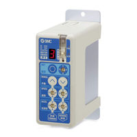
SMC LECP1, LECP2 Series - Programless Controller Step Motor (24 VDC) Manual
Brand:
SMC Corporation
| Category:
Controller
| Size: 0 MB
Table of Contents
Safety Instructions
Specifications
General specifications
Name and function of individual parts
Installation
Mounting
Environment
Wiring
Power Supply Connector
Cable / Connector specifications
Ground connection
Parallel I/O Connector
Setting
Stop position and operation mode
Auto / Manual mode setting
LED Display
How to Order
Outline Dimensions (mm)
Maintenance
General Maintenance
Limitations of Use
Limited warranty and Disclaimer/Compliance Requirements
Product disposal
Contacts
Documents / Resources
References
Advertisement
SMC Corporation LECP1 series Operation Manual (86 pages)
Programless Controller. Step Motor (servo 24 VDC)
Brand:
SMC Corporation
| Category:
Controller
| Size: 3 MB
Table of Contents
Table of Contents
2
1 Safety Instructions
5
2 Product Outline
7
Product Features
7
Product Configuration
8
How to Order
9
Actuator Cable (5M or Less)
10
Actuator Cable (8-20M)
10
Actuator Cable for with Lock and Sensor (5M or Less)
11
Actuator Cable for with Lock and Sensor (8-20M)
11
Startup Procedures
12
Confirmation of the Package Content
12
Installation
12
Wiring and Connection
12
Confirmation of the Power on Alarm
13
Data (Operation Pattern) Setting
13
Test Run
13
3 Product Specifications
14
Basic Specifications
14
Parts Description
15
Outside Dimension Diagramm
16
How to Install
17
Grounding Cable Connection
17
Installation Location
18
4 External Wiring Diagram
19
CN1: Power Supply Cable
19
CN2: Motor Power Connector and CN3: Encoder Connector
19
CN4: Parallel I/O Connector
19
5 CN1: Power Supply Cable
20
Power Supply Cable Specifications
20
Wiring of Power Supply Cable
20
Wiring of the Power Supply
20
Wiring of the Lock Release
21
Stop the Power Supply for the Motor
21
6 CN4: Parallel L/O Connector
23
Parallel I/O Specifications
23
Parallel I/O Type (NPN / PNP Type)
23
Parallel I/O Input Circuit (same for both NPN and PNP Type)
23
Parallel I/O Output Circuit
23
The Parallel I/O Signal Is Detailed
24
Parallel I/O Cable (LEC-CK4-□)
24
Derails of Input / Output Signal
24
The Change of I/O Output Signal
25
Parallel I/O Wiring Example
26
7 Setting Method
27
Setting Procedure
28
Supply of Power
28
Changes to Manual Mode
28
Return to Origin
28
Setting of Position and Operation Method
29
Test Run
35
Setting of Speed and Acceleration
35
Completion of Setting
35
Setting Parameters
36
Controller Modes
39
(A) before Return to Origin
40
(B) Auto Mode after Return to Origin
41
(C) Manual Mode after Retun to Origin
42
Test Function
43
8 Operations
44
Return to Origin
44
Positioning Operation
44
Pushing Operation
45
Successful Pushing Operation
45
Pushing Operation Is Failed (Pushing the Air)
45
Movement of the Work Piece after the Completion of the Pushing Operation
46
Jog Operation / Inching Operation
47
Servo on
48
Response Time for the Controller Input Signal
48
LED Display in Auto Mode
49
9 Operation Instruction
50
Positioning / Return to Origin
50
Pushing Operation
51
Stoppage During Operation
52
Alarm Generation and Reset
53
10 Initial Setting Value Per Electric Actuator
54
Initial Setting Value of LEF Series
54
Initial Setting Value of LEH Series
57
Initial Setting Value of LES,LESH Series
60
Initial Setting Value of LEY,LEYG Series
62
Initial Setting Value of LER Series
65
Initial Setting Value of LEPY,LEPS Series
66
Initial Setting Value of LEL Series
67
Initial Setting Value of LEM Series
68
11 Alarm Detection
69
Alarm Group Output
69
Alarm Details
70
12 Wiring of Cables / Common Precautions
73
13 Electric Actuators / Common Precautions
74
Design and Selection
74
Mounting
75
Precautions for Use
75
Operating Environment
77
Maintenance
77
Precautions for Electric Actuator with Lock
78
14 Controller and Its Peripheral Devices / Specific Product Precautions
79
Design and Selection
79
Handling
79
Installation
80
Wiring
80
Power Supply
81
Grounding
81
Maintenace
81
15 Troubleshooting
82
SMC Corporation LECP1 series Operation Manual (83 pages)
Brand:
SMC Corporation
| Category:
Controller
| Size: 3 MB
Table of Contents
Table of Contents
2
Safety Instructions
5
Outlines of Product
7
Features
7
How to Order
8
Structure of the Product
9
Procedure(How to Start the Actuator)
10
Checking the Contents of the Package
10
Mounting the Controller
10
Controller Wiring / Connection
10
Power Supply ON, and the Alarm Check
11
Data (Operation Pattern) Setting
11
Test Run
11
Specifications
12
Basic Specifications
12
Details of the Controller
13
Outer Dimensions
14
DIN Rail Mounting
14
Lecp1□□D
14
Mounting Screw
14
Lecp1
14
Mounting
15
Connection to Ground
15
Location for Mounting
16
External Connection
17
CN1: Power Supply Connector
17
CN2: Motor Power Connector, CN3: Encoder Connector
17
CN4: Parallel I/O Connector
17
CN1: Power Supply Cable
18
Power Supply Cable Specification
18
Wiring of Power Supply Cable
18
Wiring of Power Supply
18
Wiring of Forced Unlocking Switch
19
Stop the Power Supply for the Motor
19
CN4: Parallel I/O Cable
21
Paralles Input / Output
21
Parallel Input / Output Circuit (NPN, PNP)
21
Parallel I/O Input Circuit (NPN, PNP Common)
21
Parallel I/O Output Circuit
21
Parallel Input / Output Signal
22
Parallel I/O Connector Wiring (Example)
24
Setting Method
25
Setting Procedure
26
Setting Parameters
33
Controller Modes
36
(A) before Return to Origin
37
(B) Auto Mode after Return to Origin
38
(C) Manual Mode after Retun to Origin
39
Test Function
40
Operations
41
Return to Origin
41
Positioning
42
Pushing Operation
42
Successful Pushing Operation
42
Unsuccessful Pushing Operation (Idling)
43
Movement of Workpiece after Thecompletion of the Pushing Process
43
Jog / Inching Operation
44
Servo on
45
Response Time for the Controller Input Signal
45
LED Display in Auto Mode
46
Operation (Example)
47
Positioning / Return to Origin
47
Pushing Operation
48
Stoppage During Operation
49
Alarm Generation and Reset
50
Initial Setting Value Per Actuator
51
Initial Setting Value of LEF Series
51
Initial Setting Value of LEH Series
54
Initial Setting Value of LES Series
57
Initial Setting Value of LEY and LEYG Series
58
Initial Setting Value of LER Series
60
Initial Setting Value of LEP Series
61
Initial Setting Value of LEL Series
62
Initial Setting Value of LEM Series
63
Options
64
Actuator Cable [5 M or Less]
64
Actuator Cable [8 to 20M]
64
Actuator Cable (for Sensor / Lock) [5 M or Less]
65
Actuator Cable (for Sensor / Lock) [8 to 20 M]
65
Alarm Detection
66
Alarm Group Output
66
Alarms and Countermeasures
67
Wiring of Cables/Common Precautions
70
Electric Actuators/ Common Precautions
71
Design and Selection
71
Mounting
72
Handling
72
Operating Environment
74
Maintenance
75
Precautions for Actuator with Lock
75
Controller and Its Peripheral Devices / Specific Product Precautions
76
Design and Selection
76
Handling
76
Installation
77
Wiring of Cables/Common Precautions
78
Power Supply
78
Grounding
78
Maintenace
79
Troubleshooting
80
Operation Troubles
80
Position / Speed Troubles
82
Advertisement
Advertisement
Related Products
SMC Corporation LEF Series
SMC Corporation LECA6 Series
SMC Corporation LECSB
SMC Corporation LECSA
SMC Corporation LECSC
SMC Corporation LECSS
SMC Corporation LEC-BCW Series
SMC Corporation LECP6 Series
SMC Corporation LECP2 Series
SMC Corporation LECSA series
SMC Corporation Categories
Control Unit
Controller
Switch
Servo Drives
Recording Equipment
More SMC Corporation Manuals
Login
Sign In
OR
Sign in with Facebook
Sign in with Google
Upload manual
Upload from disk
Upload from URL