Sign In
Upload
Manuals
Brands
SMAR Manuals
Transmitter
Foundation 302 Series
SMAR Foundation 302 Series Manuals
Manuals and User Guides for SMAR Foundation 302 Series. We have
1
SMAR Foundation 302 Series manual available for free PDF download: Installation, Operation And Maintenance Manual
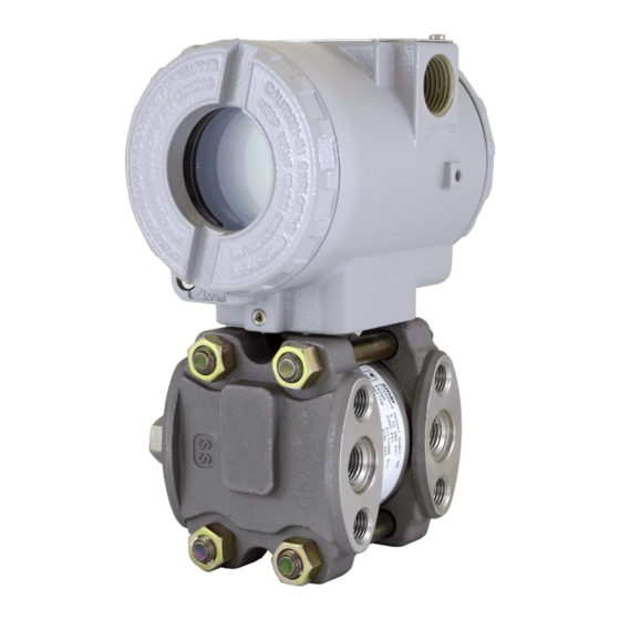
SMAR Foundation 302 Series Installation, Operation And Maintenance Manual (44 pages)
Field Devices
Brand:
SMAR
| Category:
Transmitter
| Size: 1 MB
Table of Contents
Table of Contents
3
Index of Tables
5
Introduction
5
Installation
7
Network Wiring
7
Figure 1.1 - Housing Rotation
7
Figure 1.2 - Wiring Block
7
Physical Signaling
8
Figure 1.3 - Wire Media
8
Topologies
9
Figure 1.4 - Fieldbus Network
9
Bus Topology
10
Tree Topology
10
Figure 1.5 - Bus Topology
10
Figure 1.6 - Tree Topology
10
Daisy Chain Topology
11
Figure 1.7 - Daisy-Chain Topology
11
Figure 1.8 - Daisy-Chain Wiring
11
Point-To-Point Topology
12
Fieldbus Network Components
12
Power Supply
12
Figure 1.9 - Point-To-Point Topology
12
Device Quantity
13
Terminal Blocks
13
Terminator
13
Figure 1.10 - Terminal Blocks
13
Terminator Placement
14
Psi302 Power Supply Impedance
14
Figure 1.11 - Psi302 Connection
14
Redundant Power
15
Bt302 Terminator
15
Ps302 Power Supply
15
Cabling
15
Figure 1.12 - Redundant Power
15
Cable Options
16
Total Cable Lenght
16
Table 1.1 - Cable Options
16
Figure 1.14 - Cable Entity Parameters
17
Figure 1.15 - Grounding the Shield
18
Spur Lenght
19
Recommended Maximum Spur Lenght
19
Interface and Bridge
20
Bridge Connection
20
Figure 1.17 - Bridge Connection
20
Intrinsic Safety Connection
21
Intrinsic Safety
21
Figure 1.18 - I.S. Connection
21
Table 1.4 - Temperature Classifications
22
Figure 1.19 - Repeater Connection
24
Figure 1.20 - If302 Connection
24
Figure 1.21 - Fi302 Connection
24
Attaching Devices to the Fieldbus
25
Wiring Dos and Don
25
Intrinsic Safety Galvanic Isolator
26
Figure 1.22 - Connection
26
Figure 1.23 - If302 in I. S. Installation
26
Computer Installation
27
Interface Connection
27
Figure 1.24 - Fi302 in I. S. Installation
27
Figure 1.25 - Interface Connection
27
Interface Addresing
28
Interface Configuration
28
Figure 1.26 - Interface Addressing
28
Basic Troubleshooting
29
Operation
31
The Lcd Display
31
Normal Display Operation
32
Figure 2.2 - Lcd Display
32
Table 2.1 - Display Messages
33
Configuration
35
Function Blocks
35
Display Transducer Block
35
Figure 3.2 - Transducer Display - Configuration
36
Local Programming Tree
37
Display Configuration Using Syscon
37
Table 3.1 - Parameter Function and Class Default of Device
37
Table 3.2 - Transducer Display Parameters
38
Programming Using Local Adjustment
39
Local Adjustment Methodology
39
Figure 3.7 - Local Adjustment Switches
39
Transducer Block
41
Channel
42
Calibration
42
Maintenance Procedures
43
General
43
Returning Smar Products And/Or Materials
43
Table 4.1 - Diagnostic of the Field Devices
43
Advertisement
Advertisement
Related Products
Smar DT301
SMAR DT302
SMAR DT303
SMAR LD290
SMAR LD291
Smar ld301
SMAR LD302
SMAR LD303
Smar LD400
SMAR LD400WH
SMAR Categories
Transmitter
Media Converter
Valve Positioners
Power distribution unit
Controller
More SMAR Manuals
Login
Sign In
OR
Sign in with Facebook
Sign in with Google
Upload manual
Upload from disk
Upload from URL