Sign In
Upload
Manuals
Brands
Sitex Manuals
Autopilot System
SP38 Autopilot
User Manuals: Sitex SP38 Autopilot Cable-Steer Kit
Manuals and User Guides for Sitex SP38 Autopilot Cable-Steer Kit. We have
1
Sitex SP38 Autopilot Cable-Steer Kit manual available for free PDF download: Installation And Operation Manual
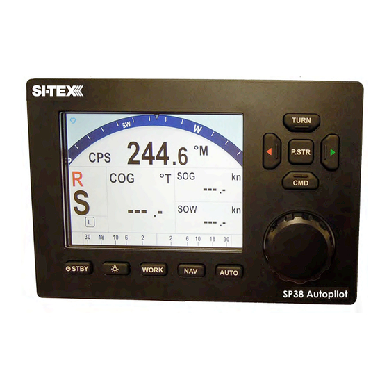
Sitex SP38 Autopilot Installation And Operation Manual (162 pages)
Advanced
Brand:
Sitex
| Category:
Autopilot System
| Size: 4 MB
Table of Contents
Installation and Operation Manual
3
Welcome
3
About this Manual
4
Table of Contents
7
How Autopilots Work
17
Manual Steering
17
Basic Autopilot System
18
Figure 1 - Basic Autopilot System
18
Figure 2 - Heading Change in AUTO Mode
21
System Overview
25
SP38 Control Head
27
Figure 3 - SP38 System Block Diagram
27
Figure 4 - Control Head
28
Signal Processor Unit
28
Figure 5 - the SP38 SPU with Wiring and Diagnostic Covers Removed
29
Compasses
30
Figure 6 - G2 GPS Compass
30
Rudder Followers
31
Figure 7 - Rotary Rudder Follower
31
Heavy Duty Rotary Rudder Follower
31
Mounting
31
Standard Rotary Rudder Follower and Rudder Linkage
31
Electrical Connections
32
Figure 8 - Rudder Follower Linkage Geometry
32
Figure 9 - Heavy Duty Rotary Rudder Follower
33
Other Equipment
34
Installation
35
Basic Requirements
37
Steering System
37
Power Supply
37
Special Tools
37
Fasteners
38
Signal Processor Unit
38
Mounting SPU
38
Wire Gauge, SPU
39
Connectors & Wiring Label, SPU
39
Table 1 - Minimum Recommended Wire Gauges
39
Figure 10A - SPU Plug Wiring Details
40
Wiring the SPU
41
Drive Box Power Supply
41
Figure 10B - SPU Connector Details
41
Power Supply (J1, Batt IN)
41
Figure 11 - Typical Battery Connection to SPU
42
3Power Supply Extension
43
Figure 12 - Reducing Supply Voltage Losses
43
Figure 13 - Wiring Connections for SP38 SPU to N2000 Networks
43
Input & Output Connections (J4, N2K000 & J7, RFU)
43
N2K Network (J7, NMEA2000)
43
Drive Outputs (J2, Motor out & J3, Drive Out)
44
Figure 14 - Wiring Connections for Rudder Followers
44
Figure 15 - Wiring Connections for Reversing DC Motors
44
Reversing DC Motor Hydraulic Systems (J2, Motor Out)
44
Rotary Rudder Follower (J4, RFU)
44
Figure 16 - Wiring Connections for Linear Actuators or Mechanical Rotary Drives
45
Figure 17 - Wiring Connections for Shunt Field Reversing Motors
45
Linear Actuators or Mechanical Rotary Drives (J2, Motor out & J3, Drive Out)
45
Shunt-Field Reversing Motors (J2, Motor out & J3, Drive Out)
45
Figure 18 - Wiring Connections for Standard Four-Way Solenoid Valves
46
Figure 19 - Wiring Connections for Constant Running Electric Pump
46
Standard Four-Way Solenoid-Activated Hydraulic Valves (J2, Motor out & J3, Drive Out)
46
Alternating Current (AC) Solenoids (J2, Motor out & J4, RFU)
47
External Alarm Output (J2, Motor out & J3, Drive Out)
47
Figure 20 - Wiring Connections for AC Solenoids
47
Figure 21 - External Alarm, Using SW'D B- Output
47
Figure 22 - External Alarm, Using SW'D B+ Output
48
Figure 23 - External Alarm, SW'D B- Output - with Power Fail Option
48
Power Failures (J1, J2 & J3)
48
Figure 24 - External Alarm, SW'D B+ Output - with Power Fail Option
49
Speed Mode and Timing Outputs (J12, MISC I/O)
49
Other Connections
50
Table 2 - Speed Mode and Timing Outputs
50
Final Steps and Post-Installation Checks for SPU Installation
51
Figure 25 - Thruster Signals for SPU-T
51
Control Head
52
Mounting Control Head
52
Figure 26 - SP38 Control Head - Rear View
52
Wiring the Control Head
53
NMEA 2000 Network Connection
53
Ethernet
53
Figure 27 - Battery Connection to Master SP38 Head
53
Other Equipment
54
Final System Installation Verificatio
54
Getting Started
55
Autopilot Operations
55
System On/Off
55
Table 3 - Turning off SP38 System
55
Using the Control Head - LCD Screen and Buttons
56
Figure 28 - Introductory Display
56
Figure 29 - Using the Control Head
56
Operating Modes and Menus Continued
59
Alarm Clear
59
Figure 30 - a Typical Menu
59
System Setup
60
Figure 31 - Autopilot in Standby Mode
60
Figure 32 - Data Sources Used by SP38 Autopilot
60
Dockside Setup
62
Vessel Type
63
Table 4 - Vessel Type
63
Alarm Output Port
64
Thrust Type
64
Figure 33 - Set Vessel Type
65
Drive Setup
66
Compass Setup
68
Figure 34 - Set Compass Type in Compass Configuration Menu
68
Sea Trials Procedures
69
Basic Operations
73
Main Menu Setup
75
Figure 35 - System Menu Tree
75
Figure 36 - System Menu Screenshot
75
Network Config Menu
79
Figure 37 - Network Configure Menu
79
Figure 38 - Dockside Menu Enter from System Menu
82
Figure 39 - SP38 System Setup
83
Setup Procedures
83
NMEA 2000 Compass to System
85
Rotary Feedback
86
Standby Menu
87
Figure 40 - Standby Menu
87
Station Lock
88
Backlight Level
89
Battery
89
Compass Cal - Compass Calibration
89
Compass Source
89
Fishzag Time
89
Power Steer Mode
90
Power Steer Menu
90
Figure 41 - Typical Power Steer Mode Screen
90
Figure 42 - Power Steer Menu
90
Stdby/P.str Limits - Power Steer Rudder Limits
91
Auto/Nav Limits
91
RAI Offset
91
Auto Mode
92
Figure 43 - Typical Auto Mode Screen
92
Figure 44 - Typical Auto Menu Screen
93
Figure 45 - Guidelines for Setting Counter Rudder
94
Parameter Set
94
Seastate
94
There Are Two Turn Rate Settings; One Is for Low Speed Operations (LO) and One Is for High Speed Operations (HI)
94
Turn Rate
94
ALC - Automatic Leeway Correction
95
Figure 46 - HI and lo Speed Icons (Left of Rudder Angle Indicator)
95
Speed Source
95
Speed Trip Pt - Speed Trip Point
95
These Two Functions Are Only Available When the Parameter Is Not Set to "None." Complete Instructions Are Included with the CT7 Thruster Interface
95
Thruster Assist / Thruster Gain
95
NAV Mode
96
Figure 47 - Typical NAV Mode Screen (Normal Display)
96
Figure 48 - Nav Menu
97
Nav Menu
97
Nav Source
97
To Access the Nav Menu, Double-Press the NAV Button
97
Waypt. Arrival - Waypoint Arrival
97
XTE Limit - Cross-Track Error Limit
97
Correction
98
Table 5 - Nav Mode Correction
98
XTE Sense - Cross-Track Error Sense
98
Commanded Heading Displayed
99
Correction Set to CTS - Steering a Direct Bearing
99
Figure 49 - Steering with Correction Set to CTS
99
Max Correction
99
Correction Set to XTE - Cross-Track Error Steering
101
Figure 50 - Steering with Correction Set to XTE
101
Correction Set to both - Steering To/Along a Track
102
Figure 51 - Response of Vessel to a Large Cross-Track Error
102
Figure 52 - Steering with Correction Set to both
103
Refer to the Navigation System's Manual for Signal Quality Measurements
103
Alternate Navigation Display
104
Dodge
104
Figure 53 - Typical NAV Mode Screen (Alternate Display)
104
Figure 54 - a Dodge in Progress (in AUTO Mode)
105
Figure 55 - Vessel Track During a Dodge Manoeuvre in AUTO Mode
105
Figure 56 - Typical Jog Lever Activated Screen
106
Advanced Operations
109
Advanced Operations
111
WORK Mode
111
Figure 57 - Typical WORK Mode Screen (Engaged)
112
Automatic WORK Mode
113
Manual WORK Mode
113
Figure 58 - Work Mode Menu
114
Work Menu
114
The States Shown Are "Off", "A_On" and "A_Rdy" (Abbreviations for Automatic on and Automatic Ready, Respectively), or "M_On" and "M_Rdy" (Manual on and Manual Ready)
115
Figure 59 - Typical Special Turn Query
116
Special Turns & Turn Menu
116
Figure 60 - U-Turn Query
117
Figure 61 - U-Turn Vessel Path
117
U-Turn
117
Circle Turn
118
Figure 62 - Circle Turn Query
118
Figure 63 - Circle Turn Vessel Path
118
Figure 64 - M.O.B. Turn Query
119
Figure 65 - M.O.B. Turn Vessel Path
119
Figure 66 - Fishzag Turn Query
120
Figure 67 - Fishzag Turn
120
Fishzag
120
Figure 68 - Turn Menu Screen
121
Figure 69 - Station Lock Icons on the Screen
122
Station Lock/Unlock
122
Care and Maintenance
123
Cleaning and Appearance
125
Protection of Wires and Cabling
125
Periodic Checks
125
Fuse Replacement
126
Appendices
127
Appendix 1
129
Appendix 1
129
NMEA 0183 Heading Sources
129
Figure 70 - NMEA 0183 / NMEA 2000 System
129
Appendix 2
130
Appendix 2
130
Non-NMEA 2000 Product Support
130
Figure 71 - GNSS G2 GPS Compass
130
Figure 72 - Typical NMEA 0183 Connections
130
Figure 73 - Fluxgate Compass
132
Figure 74 - Wiring Connections for Analog Compasses
132
Figure 75 - Externally Gimballed Magnetic Compass with Magnetic Sensor
133
Figure 76 - CR-203 Handheld Remote
135
Figure 77 - TS-203 Fixed Remote
136
Figure 78 - Wiring Connections for Control Head, Handheld and Fixed Remotes
137
Figure 79 - Jog Lever
138
Figure 80 - Wiring Connections for Jog Levers
138
Figure 81 - External Rudder Angle Indicator - 3" Model
140
Figure 82 - Wiring Connections for Rudder Angle Indicators
140
Table 6 - NMEA 0183 Sentences Accepted by the SP38
142
Table 7 - NMEA Sentence Priority
143
Appendix 3
145
Appendix 3
145
Error Messages
145
Table 8 - Warning Messages
145
Table 9 - Error Messages
146
Table 10 - Critical Error Messages
147
Appendix 4
148
Diagnostic LEDS
148
Table 11 - Diagnostic Leds
148
Appendix 5
149
Appendix 5
149
Upgrading Firmware
149
Appendix 6
150
Appendix 6
150
General Specification
150
Table 12 - General Specifications
150
Appendix 7
151
Appendix 7 Compass Safe Distances
151
Table 13- Compass Safe Distances
151
CE Compliance (European Conformity)
152
Warranty Information
153
User Notes and Settings
157
User Settings 2
159
Table 14 - User Settings
160
Advertisement
Advertisement
Related Products
Sitex Categories
Fish Finder
Autopilot System
More Sitex Manuals
Login
Sign In
OR
Sign in with Facebook
Sign in with Google
Upload manual
Upload from disk
Upload from URL