
Summary of Contents for Sitex SP38 Autopilot
- Page 1 Sitex SP38 Autopilot Advanced Autopilot Systems Installation and Operation Manual COMPLIES WITH CE REGULATIONS PN 29010101...
-
Page 3: Installation And Operation Manual
Riverhead, NY 11901 E-mail:sales@sitex.com customerservice@sitex.com Warranty Prior to the installation and/or operation of any Sitex equipment, please take a moment to read and accept all warranty conditions as detailed in the Warranty Information section of this manual. WARNING This Autopilot is for navigation assistance only. Whenever underway, your... -
Page 4: About This Manual
About this Manual This manual provides essential information for the safe and reliable operation of the Sitex SP38 Advanced Autopilot System. You are urged to read this manual in its entirety before you use your autopilot for the first time, and to keep it handy until you become thoroughly familiar with the operation of your autopilot. - Page 5 Sitex SP38 Installation and Operation Table of Contents, List of Figures and Tables Manual Format This manual has been formatted to be printed on both sides of the pages, and on standard North American Letter-size paper (8.5” x 11”). If you have obtained this manual as a soft-copy, please note that it is in Adobe® Portable Document Format (“pdf”), and so may be viewed and printed with Adobe Reader®, or...
- Page 6 Sitex SP38 Installation and Operation Table of Contents, List of Figures and Tables Document H istory Revision: Date: By: Description: 1R0 November 2 018 First R elease June 2019 2R0 ...
-
Page 7: Table Of Contents
Sitex SP38 Installation and Operation Table of Contents, List of Figures and Tables Table of Contents Installation and Operation Manual ........................2 Welcome ..........................3 About this Manual ......................... 3 Table of Contents ........................6 How Autopilots Work ......................16 Manual Steering ...............................16... - Page 8 Sitex SP38 Installation and Operation Table of Contents, List of Figures and Tables Final Steps and Post-Installation Checks for SPU installation ..............50 Control Head ..............................51 Mounting Control Head ..........................51 Wiring the Control Head ..........................52 NMEA 2000 network connection ........................ 52 Ethernet ..............................52...
- Page 9 Sitex SP38 Installation and Operation Table of Contents, List of Figures and Tables Speed Trip Pt – Speed Trip Point .......................94 Speed Source .............................94 ALC - Automatic Leeway Correction ......................94 Thruster Assist / Thruster Gain ......................... 94 These two functions are only available when the parameter is not set to “None.”...
- Page 10 Sitex SP38 Installation and Operation Table of Contents, List of Figures and Tables Appendices ........................126 Appendix 1 ...............................128 NMEA 0183 Heading Sources ........................128 Appendix 2 ...............................129 Non-NMEA 2000 Product Support ......................129 Appendix 3 ..............................144 Error Messages ............................144 Appendix 4 .................................147 Diagnostic LEDS ............................147...
- Page 11 Figure 30 – A Typical Menu ..........................58 Figure 31 – Autopilot in Standby Mode ......................59 Figure 32 – Data Sources used by SP38 Autopilot ..................59 Figure 33 – Set Vessel Type ........................... 64 Figure 34 – Set Compass Type in Compass Configuration Menu ..............67 Figure 35 –...
- Page 12 Sitex SP38 Installation and Operation Table of Contents, Lists of Figures and Tables Figure 48 – Nav Menu ............................ 96 Figure 49 – Steering with Correction set to CTS .................... 98 Figure 50 – Steering with Correction set to XTE ..................100 Figure 51 –...
- Page 13 Sitex SP38 Installation and Operation Table of Contents, Lists of Figures and Tables List of Tables Table 1 – Minimum Recommended Wire Gauges ..................38 Table 2 – Speed Mode and Timing Outputs ....................49 Table 3 – Turning Off SP38 System ....................... 54 Table 4 –...
- Page 14 Sitex SP38 Installation and Operation - 13 - Document PN 29010101 V2r0...
- Page 15 Sitex SP38 Installation and Operation Introduction - 14 - Document PN 29010101 V2r0...
- Page 16 Sitex SP38 Installation and Operation - 15 - Document PN 29010101 V2r0...
-
Page 17: How Autopilots Work
During sea trials, and later on normal operation, you may want to adjust some of those values, so that they better match your boat’s unique design dynamics. However, the information in this section can be applied in general to any Sitex autopilot, and is not necessarily specific to the P-Series. -
Page 18: Basic Autopilot System
Sitex SP38 Installation and Operation How Autopilots Work Basic Autopilot System Figure is a block diagram of the major components of an autopilot system. NAVIGATION DEVICES CONTROL HEAD DISPLAYS STATUS AND HEADING [OPTIONAL] SUPPLY NAVIGATION INFORMATION FROM THE SPU, AND... - Page 19 “RFU”), a device that tells the SPU what position the rudder is in at any given time. Autopilot Operation Maintaining a Heading: AUTO Mode With a Sitex Autopilot, following a Track or Course that you want to be on is very simple: • Set the autopilot into AUTO mode.
- Page 20 Sitex SP38 Installation and Operation How Autopilots Work • If the boat isn’t coming back on-course very quickly, the SPU’s algorithms will not back the rudder off right away, and might even move the rudder a bit farther to Starboard for a while.
-
Page 21: Figure 2 - Heading Change In Auto Mode
Sitex SP38 Installation and Operation How Autopilots Work Changing Heading Heading changes are very simple with a Sitex autopilot as well. Imagine for example, that the autopilot is steering your boat Southwest, and you now wish to change direction to Southeast (see... - Page 22 Navigation System, or it may be another device or system, like a GPS receiver (such as a Sitex GPS Compass), a LORAN C receiver, etc. (all such external devices are in general referred to in this manual using the generic term Navigation System).
- Page 23 Sitex SP38 Installation and Operation How Autopilots Work Cross and/or currents are compensated for automatically each time the Navigation System updates the Cross-Track Error. This is why NAV mode is the answer to the “track slip” problem that can occur in AUTO mode, when a cross/current exists.
- Page 24 AUTO/ALC mode is first engaged. Power Steer: “Drive by Wire” Most Sitex autopilots have a POWER STEER mode, which provides a way for the user to control the rudder directly. In effect, the autopilot acts as a sort of “electronic steering wheel”, allowing the operator to steer the boat manually, in a similar way as when using a...
-
Page 25: System Overview
Sitex SP38 Installation and Operation System Overview System Overview - 24 - Document PN 29010101 V2r0... - Page 26 Sitex SP38 Installation and Operation - 25 - Document PN 29010101 V2r0...
-
Page 27: Sp38 Control Head
Sitex SP38 Installation and Operation System Overview System Overview This chapter provides a brief description of the major elements of the SP38 Advanced Autopilot System, its functions, and their relationships to each other. Figure 3 shows a block diagram of a typical example of the SP38 electronics only system, showing the interconnections between the elements of the system. -
Page 28: Signal Processor Unit
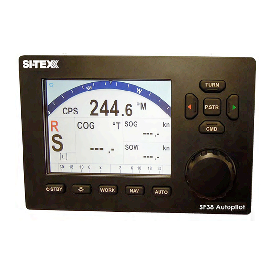
Sitex SP38 Installation and Operation System Overview Control Head PN 20140004 (SP38 Second Station Kit, Colour Head) PN 30140008 (SP38 Colour Head only) The SP38 Control Head (Figure 4) connects to a Signal Processor Unit (SPU) via NMEA 2000 NETWORK/CAN-bus through 6m NMEA 2000 standard light cables included with the units. -
Page 29: Figure 5 - The Sp38 Spu With Wiring And Diagnostic Covers Removed
2 NMEA 0183 ports. The SPU requires the rudder feedback signal sent to its analog port at J4. There are other wiring ports that are provided for the backward compactivity to Sitex older autopilots. See appendices under Legacy products for more details. -
Page 30: Compasses
System Overview Compasses The Compass is a critical component in the proper operation of the SP38 Autopilot System. The autopilot system’s ability to steer the vessel to a given Heading desired by the Operator can only be as accurate as the Compass. -
Page 31: Rudder Followers
Standard Rotary Rudder Follower and Rudder Linkage PN 20330008 and 20330007 The Sitex SP38 is normally supplied with a Sitex Medium Duty Rotary Rudder Follower. The Rudder Follower is used to transmit the position of the vessel’s rudder to the SPU. It should be connected to the part of the steering system that the autopilot controls. -
Page 32: Electrical Connections
If the length of cable supplied is too short to reach all the way to the SPU, obtain a terminal strip and sufficient additional cable from your Sitex Dealer. Mount the terminal strip in a convenient and dry location where it will not be subjected to moisture of any kind. -
Page 33: Figure 9 - Heavy Duty Rotary Rudder Follower
Sitex SP38 Installation and Operation System Overview Figure 9 – Heavy Duty Rotary Rudder Follower - 32 - Document PN 29010101 V2r0... -
Page 34: Other Equipment
Besides the optional equipment described above, there is a wide choice of other equipment available for use with the SP38 Advanced Autopilot system see Appendices for Legacy product compatibility or contact your Sitex Dealer for information and details. - 33 -... -
Page 35: Installation
Sitex SP38 Installation and Operation Installation - 34 - Document PN 29010101 V2r0... - Page 36 Sitex SP38 Installation and Operation - 35 - Document PN 29010101 V2r0...
-
Page 37: Basic Requirements
Sitex SP38 Installation and Operation Installation This chapter describes all the steps you must follow to physically install a SP38 Autopilot System into your vessel. Each of the standard components of the system are described, both physical mounting and electrical wiring, and then some final checks are provided. Commonly-used accessories are also described. -
Page 38: Fasteners
In general, fasteners are not supplied with the system – since different surfaces need various types of fasteners. However, no matter which types are best suited to your vessel, Sitex strongly recommends that you use stainless steel and/or non-corroding hardware to secure all equipment in the system. -
Page 39: Wire Gauge, Spu
Undersized wiring will result in power losses which can affect overall efficiency and performance. Refer to the table below. If in doubt, contact your Sitex Dealer for help. Once the SPU is securely mounted, you can begin wiring the various components of the system, one at a time. -
Page 40: Figure 10A - Spu Plug Wiring Details
Installation Sitex SP38 Installation and Operation Note that the plug screws must be turned counter-clockwise several turns (using a small slotted screwdriver), to open up the plug’s wire clamp, before a wire is inserted into that clamp; the screw must then be turned clockwise until the wire is tightly held in the clamp. -
Page 41: Wiring The Spu
Installation Sitex SP38 Installation and Operation Figure 10b – SPU Connector Details Wiring the SPU Power Supply (J1, Batt IN) The SP38 SPU operates on any voltage from 10VDC to 30VDC. This allows operation with vessel battery systems of nominal voltages from 12 to 24 VDC. -
Page 42: Figure 11 - Typical Battery Connection To Spu
Installation Sitex SP38 Installation and Operation Figure 11 – Typical Battery Connection to SPU - 41 - Document PN 29010101 V2r0... -
Page 43: 3Power Supply Extension
2000 drop Cable to the NMEA 2000 network. Network (J7, NMEA2000) Sitex Network is an NMEA 2000 port. A 1m Pigtail (flying end) and Male End Cable is provided to connect the SPU to NMEA 2000 network through J7. Figure 13... -
Page 44: Rotary Rudder Follower (J4, Rfu)
Drive Outputs The SP38 SPU is capable of directly driving a variety of steering systems. Optional Drive Boxes are available for those systems not directly by the SP38. Contact your Sitex Dealer for more information. Reversing DC Motor Hydraulic Systems (J2, Motor Out) Figure 15 –... -
Page 45: Linear Actuators Or Mechanical Rotary Drives (J2, Motor Out & J3, Drive Out)
Installation Sitex SP38 Installation and Operation Linear Actuators or Mechanical Rotary Drives (J2, Motor Out & J3, Drive Out) Some Linear Actuators incorporate a bypass valve. To operate properly, the bypass valve should be activated by the SW’D B+ output on the SPU. Similarly, most mechanical drives incorporate a solenoid-activated clutch. -
Page 46: Standard Four-Way Solenoid-Activated Hydraulic Valves (J2, Motor Out & J3, Drive Out)
Installation Sitex SP38 Installation and Operation Standard Four-Way Solenoid-Activated Hydraulic Valves (J2, Motor Out & J3, Drive Out) Figure Connection to 12 VDC or 24 VDC solenoids should be made as per the diagram in In this configuration, the autopilot supplies the positive voltage (SW’D B+) whenever the autopilot is in POWER STEER, AUTO, or NAV modes. -
Page 47: Alternating Current (Ac) Solenoids (J2, Motor Out & J4, Rfu)
Alternating Current (AC) Solenoids (J2, Motor Out & J4, RFU) Sitex’ s CT4 Drive Box (PN 20350003) should be used to interface between the SP38 SPU and AC solenoid systems. Connect the CT4 to the SPU as per the instructions shipped... -
Page 48: Power Failures (J1, J2 & J3)
The Note also lists a number of Piezo alarms which are known to work well with SP38 systems. Please ask your Sitex Dealer (or go to ComNav’s web site) for Application Note 2007-01. Power Failures (J1, J2 & J3) Some installations require separate monitoring for power failures. -
Page 49: Speed Mode And Timing Outputs (J12, Misc I/O)
Installation Sitex SP38 Installation and Operation The alternative circuit, using Switched B+ (SW'D B+) as the alarm output: Figure 24 – External Alarm, SW'D B+ Output – with Power Fail Option Speed Mode and Timing Outputs (J12, MISC I/O) The SP38 SPU outputs two status signals on the J12 – MISCELLANEOUS connector. -
Page 50: Other Connections
Installation Sitex SP38 Installation and Operation All three outputs are logic-level, open-drain outputs direct from the SPU’s microcontroller, and must be used only within the following voltage/current limits: Each output requires its own external pull-up resistor, which must be wired only ... -
Page 51: Final Steps And Post-Installation Checks For Spu Installation
10. If you have a NMEA 0183 compass (such as SSRC), check it is connected to NAV1 or NAV2 port 11. If you have an old Sitex CR203 or TS203, check it is connected to J10. Caution! During the first few weeks of operation, repeat the checks above at least once. -
Page 52: Control Head
Sitex SP38 Installation and Operation Installation Control Head Mounting Control Head The SP38 Control Head is typically mounted in the vessel’s wheelhouse. It can also be mounted in more exposed locations, such as on a flying bridge, since it is fully splash-proof (however be advised that the SP38 Control Head is not submersible). -
Page 53: Wiring The Control Head
Sitex SP38 Installation and Operation Installation Wiring the Control Head The SP38 Control Head operates in the same voltage range as the SP38 SPU. See 3.2.2 Wire Gauge Requirements (see Table 1) for details. Caution! The SP38 Head are NOT reverse-polarity protected. -
Page 54: Other Equipment
Sitex NF38 and TS38 Remote Controllers are NMEA 2000 devices. Installation for these devices should follow the guidance from NMEA 2000 standard. At default, SP38 autopilot uses a heading device and navigation device from the NMEA 2000 network. Refer to the manual of these devices for installation details. -
Page 55: Getting Started
Sitex SP38 Installation and Operation Installation Getting Started This chapter describes all the basic concepts you need to be familiar with when using your SP38 Advanced Autopilot System, and the steps needed to prepare it for use. Autopilot Operations After it is installed, almost all of your interaction with your autopilot system will be done by means of the Control Head. -
Page 56: Using The Control Head - Lcd Screen And Buttons
Sitex SP38 Installation and Operation Installation SP38 Autopilot, 180503049 SPU: P-SPU, 180702023 Waiting for IP... SP38 0.1, June 9/2018 Figure 28 – Introductory display If you release the STANDBY/ON/OFF button before the 3-second countdown has completed, the autopilot will abort the countdown, and remain in STANDBY mode. - Page 57 Sitex SP38 Installation and Operation Installation The elements of the Control Head (with reference to the identifiers above) are: LCD Screen. As long as the SP38 system is powered on, the LCD screen normally displays the compass heading, rudder angle, and mode of operation; it can also be displaying desired heading, system status, other information, and various menus.
- Page 58 Sitex SP38 Installation and Operation Installation 8) PORT ARROW button. Pressing and maintaining this button while in POWER STEER mode moves the rudder to port for as long as the button is held. The Rudder will remain at this position until brought back by opposite Arrow button.
-
Page 59: Operating Modes And Menus Continued
Sitex SP38 Installation and Operation Installation Operating Modes and Menus Continued Figure 30 – A Typical Menu All menus are arranged with the parameter names on the left side of the screen, and the current value for each parameter on the right side. -
Page 60: System Setup
By default, the SPU looks for heading data from the NMEA 2000 network. The Heading may come from other connection ports on the SPU. Refer to other equipment in Appendix for how to use a Sitex Magnetic Compass, a Fluxgate compass, Rate Compass or other NMEA 0183 compliant compasses. - Page 61 Sitex SP38 Installation and Operation Installation To simplify the initial match up, it is recommended after you wire the system, you only power on one device for each data type. This way, the SPU will connect the same one. If you want to use a non-NMEA 2000 data source, for example a fluxgate compass for heading, you can change the input port for a particular source.
-
Page 62: Dockside Setup
Sitex SP38 Installation and Operation Installation Dockside Setup Before the SP38 Autopilot can steer your vessel, at the minimum, you need to go through the Drive Setup to fit the SPU drive circuit with your steering system. This is done through the Dockside Setup... -
Page 63: Vessel Type
Sitex SP38 Installation and Operation Installation Vessel Type Set the vessel type to match (as closely as possible), the kind of craft that the autopilot is being installed on. The system then automatically selects a specific set of equations and constants –... -
Page 64: Alarm Output Port
Sitex SP38 Installation and Operation Installation Drive Setup Pressing the ENTER button when this line is highlighted starts a script in which the autopilot automatically determines the orientation of the Rudder Follower Unit, measuring the physical limits of the rudder’s range of motion, figures out what kind of steering system (i.e. -
Page 65: Figure 33 - Set Vessel Type
- Vessel Type). Figure 33 – Set Vessel type NOTE: At this step in the setup process, all of the various Vessel Types (Displacement, Stern, Semi, etc.) can be selected, for SP38 autopilot. - 64 - Document PN 29010101 V2r0... -
Page 66: Drive Setup
“Drive”, as used on the menus, sometimes refers to the hydraulic and/or electrical system that the boat uses to control the steering mechanism (rudder, etc.), and other times to the mechanism itself). If you continue to have problems, contact your Sitex Dealer for assistance. - 65 - Document PN 29010101 V2r0... - Page 67 Sitex SP38 Installation and Operation Installation Drive Setup Continued After detecting the drive type, a SP38 with an RFU gives you the option to bleed your hydraulic steering system. If you wish to do this, please refer to the hydraulic system’s manual.
-
Page 68: Compass Setup
Sitex SP38 Installation and Operation Installation Compass Set-up Figure 34 and press ENTER. The list of all Highlight Compass Setup shown in four supported compass heading sources will be displayed (see Table Figure 34 – Set Compass Type in Compass Configuration menu... -
Page 69: Sea Trials Procedures
Connect the gyro compass to NAV1 port b. Change the selection for NAV1 from NMEA to SSRC. Note: you should do compass calibration at the start of the sea trials. For Sitex Fluxgate compass follow Dockside Menu instruction for compass Calibration process. For Rate Compass (SSRC), follow Rate compass manual instructions enclosed with the unit. - Page 70 Sitex SP38 Installation and Operation Installation 4. Start with “Rudder Gain” and “Counter Rudder” set to the factory defaults (for Hi): 5 and 3. 5. Highlight “Seastate” and set it to 1. 6. Highlight “Turn Rate.” Select a setting that is approximately ¾ of your boat’s comfortable turning rate at a normal cruising speed (to find your “Comfortable...
- Page 71 Sitex SP38 Installation and Operation Installation Adjust Seastate for Hi Speed 1. To set Seastate, switch to AUTO mode, and then watch the Port and Starboard rudder movement arrows at the ends of the screen’s RAI bar. In normal conditions, there should be rudder movement about 15% to 20% of the time.
- Page 72 Sitex SP38 Installation and Operation Installation Some suggestions and points to keep in mind: Typically, you will find that you will only need to make small changes to the “calm condition” steering parameters already set, to handle a wide variety of sea conditions.
-
Page 73: Basic Operations
Sitex SP38 Installation and Operation Basic Operation Basic Operations - 72 - Document PN 29010101 V2r0... - Page 74 Sitex SP38 Installation and Operation - 73 - Document PN 29010101 V2r0...
-
Page 75: Main Menu Setup
Sitex SP38 Installation and Operation Basic Operation Main Menu SP38 System allows user to adjust the screen to suit backlight, time, language and many other useful parameters. See below in Figure 35 for a full list of menu items. System Layout Each menu item can be adjusted allowing comfortable screen displays and data readings. - Page 76 Sitex SP38 Installation and Operation Basic Operation The System menu has all of the adjustable parameters that are involved with the SP38 Head Display. To access the System menu, double-press the CMD button for the MAIN Menu, and then press the TURN KNOB button to select.
- Page 77 Sitex SP38 Installation and Operation Basic Operation Distance Unit There are four Distance Unit choices: m (Meter), Km (Kilometer), mil (Miles), nm (Nautical Miles). Speed Unit There are four Speed Unit choices: m/s (meter/second), Km/s (Kilometer/second), mph (mile/second), Kn (Knots)
- Page 78 This provides the following information for the SP38 Head on a N2K network: Network addr. (Network address eg.21) Manufacturer (404 for Sitex devices) Model ID (Sitex Product Model: SP38 Autopilot) S/W (Software Revision e.g. SP38 Head SPU Info...
-
Page 79: Network Config Menu
Navigation Source, multiple SP38 SPUs’ and multiple SP38 Heads’ that are involved with a SP38 Autopilot connecting to a NMEA 2000 Network. To access the Network Config menu, double-press the CMD button to bring up the MAIN Menu and then press TURN KNOB to select. - Page 80 Allows users to select one SPU from multiple SPUs on the NMEA 2000 network. Please note that the screen will show all the devices on the NMEA 2000 Network, you must then select the device with “Sitex SPU.” Selecting a device which is not SPU, will show an error message.
- Page 81 Data Source (PGN) on the network, the SP38 Autopilot will pick the first that is available. If there is none available, the SP38 Autopilot will do nothing. It is up to the user to confirm they are using the correct data for navigations.
-
Page 82: Figure 38 - Dockside Menu Enter From System Menu
Sitex SP38 Installation and Operation Basic Operation Setup Menu Figure 38 - Dockside Menu Enter from System Menu Set up the adjustable parameters for use in “STANDBY (User Config.), Power Steer (P. Steer), AUTO, NAV, Work mode & Turn” modes which are stored in the SP38 SPU. Please see the parameter descriptions under “Basic &... -
Page 83: Setup Procedures
Sitex SP38 Installation and Operation Basic Operation Setup procedures For typical Sitex SP38 NMEA 2000 system - SP38 Head and SPU with NMEA 2000 Compass and Rotary Feedback, do the following: NMEA 2000(N2K) Connection - Trunk (Backbone) cable NMEA 2000(N2K) Connection - 6m drop cable, Male & Female (PN31110052) NMEA 2000(N2K) Connection - 6m cable, Pigtail &... - Page 84 Sitex SP38 Installation and Operation Basic Operation For “No Link” to SPU: Repair and Reset: 1. Make sure the NMEA 2000 wires are connected to the SPU properly. 2. Press the Enter button to acknowledge alarm 3. Press and hold the CMD button to take control 4.
-
Page 85: Nmea 2000 Compass To System
Sitex SP38 Installation and Operation Basic Operation For “Faulty Head” The “NO COMMAND HEAD” alert identifies a connection failure to the SPU upon initial start- up. The “Compass error” alert occurs when the SPU can’t identify the Compass source. To correct either of these alerts, do the following: 1. -
Page 86: Rotary Feedback
Sitex SP38 Installation and Operation Basic Operation To configure NMEA 2000 Compass as HDG (Heading Source) and/or POS (Position Source) 1. Press Enter to acknowledge the alarm 2. Press the CMD button to take control 3. Double Press the CMD button to bring up the menu. -
Page 87: Standby Menu
Sitex SP38 Installation and Operation Basic Operation Standby Menu The Standby menu consists of a number of items that have a general bearing on how the autopilot operates. To access the Standby menu, double-press the red STANDBY/ON/OFF button. * To get the full menu, it must be Standby mode. -
Page 88: Station Lock
Sitex SP38 Installation and Operation Basic Operation Station Lock The SP38 system can have many Control Stations limited only by the NMEA 2000 network. One of these Control Stations is always the main control, and the others are simply repeater stations. -
Page 89: Compass Source
Sitex SP38 Installation and Operation Basic Operation Compass Source There are a number of separate inputs for the many different types of compasses that may be used with the SP38 (N2000, Analog, Nav1 and Nav2) system. You may choose to have more than one type connected at any given time. -
Page 90: Power Steer Mode
Sitex SP38 Installation and Operation Basic Operation Power Steer Mode To enter POWER STEER mode, press and hold the P.STR button for approximately half a second, until the large “P” mode indicator appears in the upper left corner of the display... -
Page 91: Stdby/P.str Limits - Power Steer Rudder Limits
Sitex SP38 Installation and Operation Basic Operation Stdby/P. Str Limits - Power Steer Rudder Limits When you initially set up the SP38 system, you will move the rudder from hard over port to hard over starboard so that the autopilot can measure these positions. -
Page 92: Auto Mode
Sitex SP38 Installation and Operation Basic Operation Auto Mode In AUTO mode, the autopilot will steer the vessel on your desired Heading. To enter AUTO mode, press and hold the AUTO button for about 1 second, until the large letter `A´ appears... -
Page 93: Figure 44 - Typical Auto Menu Screen
Sitex SP38 Installation and Operation Basic Operation If you need to, you can quickly “dodge” around obstacles, and automatically Notes on AUTO Mode return to your original Commanded Heading when the boat is clear of the obstacle, without having to turn the COURSE CHANGE knob. -
Page 94: Seastate
Sitex SP38 Installation and Operation Basic Operation Like Rudder Gain, there are two numbers shown; one for LO speed, and one for HI speed. The parameter values do not have any units. The following diagram provides a general guide to setting Counter Rudder: Figure 45 –... -
Page 95: Speed Trip Pt - Speed Trip Point
Sitex SP38 Installation and Operation Basic Operation When the SP38 is in AUTO or NAV mode, it always indicates which steering parameter set is in effect. This is shown just to the left of the Rudder Angle Indicator, and consists of a small box shape with either H for Hi or L for Lo in it. -
Page 96: Nav Mode
Sitex SP38 Installation and Operation Basic Operation NAV Mode In NAV mode, the SP38 Advanced Autopilot system can use steering information from an external NMEA 0183 Navigation System, to steer to a destination, or along a route of waypoints leading to a final destination. -
Page 97: Nav Menu
Sitex SP38 Installation and Operation Basic Operation Nav Menu The Nav menu contains a number of parameters used when operating the autopilot in NAV mode. To access the Nav menu, double-press the NAV button. LEVEL 1 LEVEL 2 LEVEL 3 Nav Source N2000, Nav1 &... -
Page 98: Correction
Sitex SP38 Installation and Operation Basic Operation Auto (automatic sequencing): Displays “Waypoint Arrival” on the Control Head screen, accompanied by an audible • alarm. However, the autopilot will automatically turn the vessel to the next waypoint in a route even if the alarm is not acknowledged by pressing the ENTER button. -
Page 99: Max Correction
Sitex SP38 Installation and Operation Basic Operation Because of this confusion, the SP38’s handling of XTE can be switched from “Norm” (normal) to “Rev” (reverse). In “Norm”, the autopilot will respond normally to the sense of the cross-track error. In “Rev”, the autopilot will respond in the opposite way in response to the same information. - Page 100 Sitex SP38 Installation and Operation Basic Operation Test this out to be familiar with it, by performing the following steps: 1) Change “Correction” in the Nav menu to “CTS” 2) Make sure the Navigation System is turned on and that a waypoint is programmed in.
-
Page 101: Correction Set To Xte - Cross-Track Error Steering
Sitex SP38 Installation and Operation Basic Operation Correction set to XTE – Cross-Track Error Steering Cross-track error is the perpendicular distance from the track to the vessel’s position. When using Cross-Track Error Steering, the autopilot initially steers on its present heading, and monitors the Cross-Track Error reported by the Navigation System. -
Page 102: Correction Set To Both - Steering To/Along A Track
Sitex SP38 Installation and Operation Basic Operation If there is a large cross-track error, the autopilot may overshoot the intended track. This is a function of turn rate, vessel speed, and position updates received from the Navigation System. For best performance, it is always best to minimize any cross-track error before putting the autopilot into NAV mode. -
Page 103: Refer To The Navigation System's Manual For Signal Quality Measurements
Sitex SP38 Installation and Operation Basic Operation Figure 52 – Steering with Correction set to Both When steering along a track, the SP38 tries to minimize cross-track error by steering to a heading that lies between the perpendicular to the track and the destination waypoint. The farther you are off track, the closer to the perpendicular the heading will be. -
Page 104: Alternate Navigation Display
Sitex SP38 Installation and Operation Basic Operation Alternate Navigation Display An alternative display is available for NAV mode. To access this display, enter NAV mode by pressing the NAV button until the letter “N” appears in the upper left portion of the display. -
Page 105: Figure 54 - A Dodge In Progress (In Auto Mode)
Sitex SP38 Installation and Operation Basic Operation Once the button is released, the Autopilot will turn the vessel back to the commanded course (i.e., Heading, Track, or Angle, depending on which operating mode is in effect). Figure 54 – A Dodge in Progress (in AUTO Mode) Caution! During a Dodge turn (for example, while one of the ARROW buttons is maintained), the Autopilot will not limit the rate of turn of the vessel. -
Page 106: Figure 56 - Typical Jog Lever Activated Screen
Sitex SP38 Installation and Operation Basic Operation If desired, you can also bring the rudder back to centre (Dead Ahead) part-way through a Dodge. For example, you might want to center the rudder in order to maintain a temporary but specific Heading that the vessel has reached during the dodge. - Page 107 Sitex SP38 Installation and Operation Basic Operation If one or both of the Power Steer Rudder Limits and/or the Auto/NAV Limits are set, then • the autopilot will stop moving the rudder when it gets to the smaller of the limits.
- Page 108 Sitex SP38 Installation and Operation - 107 - Document PN 29010101 V2r0...
-
Page 109: Advanced Operations
Sitex SP38 Installation and Operation Advanced Operations - 108 - Document PN 29010101 V2r0... - Page 110 Sitex SP38 Installation and Operation - 109 - Document PN 29010101 V2r0...
-
Page 111: Advanced Operations
Sitex SP38 Installation and Operation Adanced Operation Advanced Operations This chapter describes the advanced modes of operation and features of a P-Series system, and shows you how to use them. WORK Mode WORK mode is a special mode, for use in conditions that are different than normal autopilot operation. -
Page 112: Figure 57 - Typical Work Mode Screen (Engaged)
Sitex SP38 Installation and Operation Advanced Operation Figure 57 – Typical WORK Mode Screen (Engaged) To disable WORK mode, press the WORK button again, for approximately 1 second, until a confirming beep is heard and the letter `W´ disappears from the display. WORK mode can also be cancelled by switching to either STANDBY or POWER STEER mode. -
Page 113: Automatic Work Mode
Sitex SP38 Installation and Operation Advanced Operation Rudder Bias will be the first line on the list, and will show the current helm bias. You can change this value to suit, using the COURSE CHANGE knob. This feature is useful in order to accommodate changing load or sea conditions. -
Page 114: Work Menu
Sitex SP38 Installation and Operation Advanced Operation Work Menu The Work menu has all of the adjustable parameters that are involved with WORK mode. To access the Work menu, double-press the WORK button. LEVEL 1 LEVEL 2 LEVEL 3 Autotrim Manual &... -
Page 115: The States Shown Are "Off", "A_On" And "A_Rdy" (Abbreviations For Automatic On And Automatic Ready, Respectively), Or "M_On" And "M_Rdy" (Manual On And Manual Ready)
Sitex SP38 Installation and Operation Advanced Operation Work T rip P t. -‐ W ork T rip P oint This is the speed below which WORK mode can be engaged, and above which WORK mode will be disengaged automatically. -
Page 116: Special Turns & Turn Menu
Sitex SP38 Installation and Operation Advanced Operation Special Turn and Turn Menu Pre-define Special Turns There are a number of Special Turns pre-programmed into the SP38 system. Special Turns can be executed only in AUTO and NAV modes. To execute a Special Turn (with the autopilot in the appropriate mode): 1) Press the TURN button. -
Page 117: U-Turn
Sitex SP38 Installation and Operation Advanced Operation U-Turn For a U-Turn, the autopilot calculates a reciprocal course to the vessel’s heading, and then turns the vessel to that heading, in the appropriate direction, once the PORT or STARBOARD ARROW button is pressed. -
Page 118: Circle Turn
Sitex SP38 Installation and Operation Advanced Operation Circle Turn For a circle turn, the autopilot steers a never-ending circle in the appropriate direction once the PORT or STARBOARD ARROW button is pressed. The Turn Rate setting in the Auto menu governs the rate of turn. -
Page 119: Figure 64 - M.o.b. Turn Query
Sitex SP38 Installation and Operation Advanced Operation M.O.B. – Man Over-Board The autopilot can perform a Williamson / Man Overboard turn, sometimes known as an Emergency or E-turn. This will bring the vessel onto a reciprocal heading; typically, right down the vessel’s own wake. -
Page 120: Fishzag
Sitex SP38 Installation and Operation Advanced Operation Pre-Tack Turn For a Pre-Tack turn, the autopilot makes a course change in the degrees set by the Pretack Angle. Pre-Tack Angle is set in Turn Menu. Fishzag As its name implies, the Fishzag turn was developed specifically for fishing. -
Page 121: Figure 68 - Turn Menu Screen
Sitex SP38 Installation and Operation Advanced Operation Turn Menu The TURN menu has all of the adjustable parameters that are involved with TURN mode. To access the TURN menu, double-press the TURN button. LEVEL 1 LEVEL 2 LEVEL 3 On & Off... -
Page 122: Station Lock/Unlock
Sitex SP38 Installation and Operation Advanced Operation Station Lock/Unlock Setting the Station Lock parameter in the Standby menu to Lock prevents any of the Repeaters from being able to take command. When station lock is set to Lock, the image of a key will be shown in the upper right corner of the display, next to the repeater R. -
Page 123: Care And Maintenance
Sitex SP38 Installation and Operation Care and Maintenance - 122 - Document PN 29010101 V2r0... - Page 124 Sitex SP38 Installation and Operation - 123 - Document PN 29010101 V2r0...
-
Page 125: Cleaning And Appearance
Sitex SP38 Installation and Operation Care and Maintenance Care and Maintenance The SP38 Advanced Autopilot System has been designed to provide many years of reliable service. The following periodic care and maintenance tips will help to ensure the longevity of your autopilot. -
Page 126: Fuse Replacement
Sitex SP38 Installation and Operation Care and Maintenance Fuse Replacement There are two fuses used on the SPU. Replace fuses only with the same type and rating, as per the table below. Should a fuse blow, determine the cause before replacing. -
Page 127: Appendices
Sitex SP38 Installation and Operation Appendices - 126 - Document PN 29010101 V2r0... - Page 128 Sitex SP38 Installation and Operation - 127 - Document PN 29010101 V2r0...
-
Page 129: Nmea 0183 Heading Sources
Appendices Appendix 1 NON- NMEA 2000 Heading Sources The following is how to install and connect a Sitex Magnetic/Fluxgate Compass and Rotary Feedback Follower. NMEA 2000(N2K) Connection - Trunk (Backbone) cable NMEA 2000(N2K) Connection - 6m drop cable, Male & Female (PN31110052) NMEA 2000(N2K) Connection - 6m cable, Pigtail &... -
Page 130: Non-Nmea 2000 Product Support
PN 11220012 or 11220013 (G2) – NMEA0183 model with 15 or 30 metre cable PN 11220014 or 11220015 (G2B) – NMEA0183 model with 15 or 30 metre cable The Sitex GPS Compasses are state-of-the-art devices which can provide accurate 2D Heading and Position data to autopilots, sonar, chart-plotters, AIS transponders. - Page 131 Sitex SP38 Installation and Operation Appendices For standard installation, Port 1 of GNSS compass is set for GPS (SOG, COG) signals and Port 2 of GNSS compass is set to compass signals (HDT) signal. For proper operation, the connected device(s) must fully comply with NMEA 0183 Standard (version 3.00):...
-
Page 132: Figure 73 - Fluxgate Compass
J9 – C (see the Compass section for how to connect NMEA compasses. OMPASS If you ordered your SP38 system with a Sitex Fluxgate Compass, the cable wires connect to the J9 receptacle, as per the diagram in Figure... -
Page 133: Figure 75 - Externally Gimballed Magnetic Compass With Magnetic Sensor
5. Select Compass Setup 6. Select Analog Compass from none to Flux 7. It will display “Sitex Fluxgate found” 8. After Dockside, the screen returns to “Compass” 9. Select “Exit” on the Dockside Setup Menu, DO NOT use the MENU button to go to the previous screen. - Page 134 Sitex SP38 Installation and Operation Appendices To configure a Magnetic compass: 1. Enter SPU DOCKSIDE Menu: power-down & up the system, press LEFT & RIGHT ARROW KEYS <> at the same time when the instruction is on the screen. Note that the “D”(Dockside Setup Menu) on the left side of the screen 3.
-
Page 135: Figure 76 - Cr-203 Handheld Remote
Sitex SP38 Installation and Operation Appendices P-Series Remote (Remote CR203 & TS203): CR-203 Remote PN 20310026 – 12m (40’) cable PN 20310028 – 18m (60’) cable The CR-203 Handheld Remote is specifically designed to operate with the Commander P2 Advanced Autopilot System. The CR-203 Remote provides selection of STANDBY, TILLER, AUTO, and NAV mode. -
Page 136: Figure 77 - Ts-203 Fixed Remote
Sitex SP38 Installation and Operation Appendices TS-203 Remote PN 20310025 The TS-203 Fixed Remote is a heavy duty Full-Follow-Up (FFU) Lever control which allows the operator to control the tiller steering and autopilot functions from any work station, flying bridge or remote location on the vessel. -
Page 137: Figure 78 - Wiring Connections For Control Head, Handheld And Fixed Remotes
Sitex SP38 Installation and Operation Appendices If you have P-Series Remote such as CR203 or TS203, wire them into the plug mated to the receptacle labelled J10 – Control Head as the following diagram. Control Head Connection PLUG INTO PLUG INTO J10 –... -
Page 138: Figure 79 - Jog Lever
Sitex SP38 Installation and Operation Appendices Other Controls, Indicators and Sensors Jog Levers PN 20310002 (1 set of switches) PN 20310003 (2 sets of switches) ComNav’s Non-Follow-Up (NFU) Jog Lever is a permanently mounted, watertight, electrical switch specifically designed for marine use. The spring-centered lever is moved port or starboard as desired to provide non-follow-up (time dependent) electrical control of the vessel’s steering system. - Page 139 Sitex SP38 Installation and Operation Appendices In order to use the Jog Levers connected in the above manner, the autopilot must be turned on. The autopilot will then move the rudder either port or starboard for as long as the Jog Lever is held activated.
-
Page 140: Figure 81 - External Rudder Angle Indicator - 3" Model
Rudder Angle Indicator (RAI) – 3” PN 20360014 The Sitex RAI is a backlit 3” (76 mm) diameter gauge that displays the actual position of the vessel’s rudder. The RAI is flush mounted, encased in high impact resistant polycarbonate plastic with a water resistant front face, and requires a lighting voltage supply of 12, 24 or 32 VDC. - Page 141 Sitex SP38 Installation and Operation Appendices Appendix 3 NMEA 2000 PGN numbers Accepted and Transmitted by the Autopilot Transmitting standard PGNS 59392, 59904, 60928, 126996, 126464, 126208, 127250, 127245, 127237, 128259, 129025, 129026, 129283, 129284, 126993 Receiving standard PGNs...
-
Page 142: Table 6 - Nmea 0183 Sentences Accepted By The Sp38
Sitex SP38 Installation and Operation Appendices NMEA 0183 Sentences Accepted and Transmitted by the Autopilot The SP38 Advanced Autopilot system receives and transmits serial data in NMEA 0183 format. Messages Accepted The SP38 accepts the following NMEA 0183 sentences (the * in front of the sentences... -
Page 143: Table 7 - Nmea Sentence Priority
Sitex SP38 Installation and Operation Appendices Sentence Priority Data Used Sentence (larger number is higher priority) Magnetic heading *HDM True heading *HDT Magnetic heading, *HDG Magnetic variation Range to waypoint *BWC Vessel speed *VTG Vessel speed *VHW Vessel speed *VBW... - Page 144 1) $ ⇒ the symbol that starts all NMEA 0183 sentences 2) P ⇒ identifies a proprietary sentence 3) CMN ⇒ the identifier assigned to Sitex Marine Ltd. by NMEA 4) S ⇒ status type sentence 5) Mode: SB ⇒ STANDBY mode, PS ⇒ POWER STEER mode,...
-
Page 145: Error Messages
Error Messages There are a number of different error messages that display for varying reasons and at different times in the SP38 autopilot system. These messages are displayed on the Control Head screen, and are usually accompanied by an audible alarm. -
Page 146: Table 9 - Error Messages
Sitex SP38 Installation and Operation Appendices The following messages are classified are “severe” errors. Typically, these messages describe a condition that prevents normal operation in the current mode, but operation in other modes may still be possible. The error messages may be temporarily suppressed by... -
Page 147: Table 10 - Critical Error Messages
Check all wiring as well as the battery/batteries. The SP38 has detected a problem in its program ROM ERROR memory. Return the unit to your Sitex Dealer for repair. The SP38 cannot detect the presence of a Rudder Follower Unit. -
Page 148: Diagnostic Leds
Sitex SP38 Installation and Operation Appendices Appendix 4 Diagnostic LEDs The Signal Processor Unit is equipped with a number of Light-Emitting Diode (LED) lamps that can assist in trouble-shooting should a problem arise with the autopilot system. To observe the LEDs, remove the metal cover on the Diagnostic section. -
Page 149: Upgrading Firmware
Sitex is constantly doing research and development related to our Autopilot Systems. From time to time, this can result in new features and benefits that can be incorporated into an existing system installation, in the field – by a Sitex Dealer, or even by the vessel operator. -
Page 150: General Specification
Sitex SP38 Installation and Operation Appendices Appendix 6 General Specifications Parameter Specification Dimensions 218x 152 x 62 mm (10.6” x 5.6”x 2.4”) Bracket Mount Head 157 x 118 x 73 mm (6.2 x 4.6 x 2.9”) @ 20° max tilt –... -
Page 151: Compass Safe Distances
Sitex SP38 Installation and Operation Appendices Appendix 7 Compass Safe Distances The following Compass Safe Distances were determined using a UKAS calibrated 23 Axis Magnetometer, for both standard compasses and steering/emergency compasses. Standard Steering Compass Compass Sitex PN Description Limit Limit 5.4°/H... -
Page 152: Ce Compliance (European Conformity)
Annex A, Section A.6: Immunity to Radiated Interference Test results and a declaration of conformity are on file at the Sitex Head Office. SI-TEX Marine Electronics 25 Enterprise Zone Drive, Ste 2 Riverhead, NY 11901 - 151 -... -
Page 153: Warranty Information
Sitex SP38 Installation and Operation Warranty Warranty Information CERTIFICATE OF LIMITED WARRANTY Providing you present valid proof of purchase, SI-TEX Marine Electronics warrants all parts of each new product against defects in material and workmanship under normal use and will repair or exchange any parts proven to be defective at no charge for a period of two years from the original date of purchase, except as provided below under Limited Warranty Exceptions. - Page 154 Sitex SP38 Installation and Operation Warranty THERE ARE NO WARRANTIES OR GUARANTEES EXPRESSED OR IMPLIED WHICH EXTEND BEYOND THE DESCRIPTION OF THE FACE HEREOF, INCLUDING WARRANTIES OF FITNESS FOR A PARTICULAR PURPOSE AND MERCHANTABILITY. SI-TEX MARINE ELECTRONICS HAS NO OTHER LIABILITY TO PURCHASE FOR DIRECT OR CONSEQUENTIAL DAMAGE OR ANY THEORY INCLUDING ABSOLUTE LIABILITY, TORT, OR CONTRACT.
- Page 155 CUSTOMER SERVICE If you encounter problems during the installation or operation of this product, or cannot find the information you need, please contact Sitex Customer Service. The contract numbers and e-mail address for Sitex Customer Service are: Sitex Main Office ……………….+1-631-996-2690 Sitex Fax…………………………+1-631-996-2693...
- Page 156 Sitex SP38 Installation and Operation Warranty - 155 - Document PN 29010101 V2r0...
-
Page 157: User Notes And Settings
Sitex SP38 Installation and Operation User Notes and Settings - 156 - Document PN 29010101 V2r0... - Page 158 Sitex SP38 Installation and Operation - 157 - Document PN 29010101 V2r0...
-
Page 159: User Settings 2
User Notes and Settings Sitex SP38 Installation and Operation User Settings Once your SP38 system has been installed and set up correctly, make a record of all the settings for future reference, in the table below. Parameter Range Default Value... -
Page 160: Table 14 - User Settings
User Notes and Settings Sitex SP38 Installation and Operation Parameter Range Default Value User Settings 1 User Settings 2 Power Steer Menu Stdby/P. Str Off, or 5° up to physical limits Rudder Limits from Dockside Setup Auto/Nav Rudder Off, or 5° up to physical limits... - Page 161 User Notes and Settings Sitex SP38 Installation and Operation Parameter Range Default Value User Settings 1 User Settings 2 Work Menu Auto/Nav rudder limit or physical Rudder Bias Set at Runtime limit Autotrim Off, On Work Trip Pt. 1 – 10 Rudder Scale 0.25 –...
- Page 162 User Notes and Settings Sitex SP38 Installation and Operation User Notes - 161 - Document PN 29010101 V2r0...
Need help?
Do you have a question about the SP38 Autopilot and is the answer not in the manual?
Questions and answers