Sign In
Upload
Manuals
Brands
Sinee Manuals
Inverter
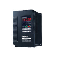
EM303A-0R4-2CB
User Manuals: Sinee EM303A-0R4-2CB Inverter
Manuals and User Guides for Sinee EM303A-0R4-2CB Inverter. We have
1
Sinee EM303A-0R4-2CB Inverter manual available for free PDF download: User Manual
Sinee EM303A-0R4-2CB User Manual (140 pages)
EM303A series General Purpose Inverter
Brand:
Sinee
| Category:
Inverter
| Size: 2 MB
Table of Contents
Safety Information
2
Safety Precautions
2
Table of Contents
6
Model List of EM303A-XXX-1C
8
Model List of EM303A-XXX-2C
8
Supplement for EM303A-XXX-1C, EM303A-XXX-2C
8
Overview
9
EM303A Model List and Technical Specifications
9
EM303A Model and Rated Output Current
9
Model List of EM303A
9
EM303A Technical Specifications
10
Basic Functions of EM303A
11
Process PID Control
11
Program Operation (Simple PLC)
11
Wobbulation Operation (Textile Only)
11
Low Noise Design
12
Current Limit
12
Energy Autosaving
12
Constant Power Output
12
EM303A Operation Status Definition
13
Multi-Function Numeric Input Terminals
13
Multi-Function Analog Output Terminals
13
Multi-Function Numeric Output Terminal
13
Control Modes of Inverter
14
Setting Modes of Inverter
14
Speed Setting Modes
15
Torque Input Mode
16
EM303A Outlook
17
Operation Control Mode of Inverter
17
Control Circuit Terminal Block
17
Main Circuit Terminal Block
17
2 Installation
18
Verifying Product
18
Nameplate
18
Model Numbering Scheme
18
Overall and Installation Dimensions
19
Keypad Dimensions for Installation
19
Overall and Keypad Dimensions of EM303A for Installation
19
Overall and Installation Dimensions of EM303A
20
Considerations of Installation Site
21
Direction and Space of Installation
21
Ambient Temperature
21
Installation Direction and Space
21
Disassembly and Assembly of Keypad
22
Remove the Front Cover
22
Disassemble the Keypad
23
Assemble the Keypad
23
3 Wiring
24
Connections to Peripherals
24
EM303A Peripherals Connections
24
Wiring Main Circuit Terminals
25
Main Circuit Terminal Functions
26
Standard Wiring of Main Circuit
26
Wiring Main Circuit on Input Side
26
Installing a Circuit Breaker
26
Installing a Leakage Circuit Breaker
27
Installing an Electromagnetic Contactor
27
Connecting to the Terminal Block
27
Installing an AC Reactor
27
Installing a Surge Absorber
28
Installing a Noise Filter on Power Supply Side
28
Connecting the Inverter to Motor
28
Wiring the Output Side of Main Circuit
28
Never Connecting Power Supply Cable to Output Terminals
29
Never Short-Circuiting or Grounding Output Terminals
29
Never Using a Phase-Shifting Capacitor
29
Installing a Noise Filter on the Output Side
29
Countermeasures against Radio Frequency Interference (RFI)
30
Cable Length between Inverter and Motor
30
Countermeasures against Inductive Interference
30
Countermeasures against RFI
30
Main Circuit Cable and Terminal Screw Size
31
Main Circuit Cable and Terminal Screw Specifications
31
Ground Wiring
32
Wiring Braking Resistor and Braking Unit
32
Wiring Control Circuit Terminals
32
Function and Wiring of Control Circuit Terminals
33
Wiring the Analog Input Terminals
34
Wiring Multi-Function Input Terminal
34
Wiring of Terminals VS and VF
34
Wiring of Terminals IS and if
34
Wiring Relay Output Terminal
35
Wiring Multi-Function Output Terminal
35
Wiring Analog Output Terminals
35
Wiring Communication Terminal
36
Size of Control Circuit Cable and Screw
36
Control Circuit Wiring Precautions
36
Connect to PC or PLC through RS485 Terminal
36
Standard Control Circuit Wiring
37
Extending Keypad Wire
38
Wiring Check
38
Disassemble the Keypad and Connect Extension Keypad Wire
38
4 Keypad Operation
39
Type and Function of Keypad
39
LED Keypad
39
LED Keypad Operation Mode
40
5 Trial Operation
41
Trial Operation Procedures
41
Procedures of Trial Operation
41
Trial Operation Precautions
43
Turn off the Power
43
Check at Power-On
43
Idling Operation
43
On-Load Operation
44
Operation Status Monitoring
44
Connecting Motor to Mechanical Load
44
Starting up the Inverter
44
6 Parameter Tables
45
Format of Parameter Tables
45
Unit and Its Abbreviation
45
Group F0: General Parameters
46
Section 1 General Parameters
46
Group F1: Motor Parameters
48
Group F2: Input/Output Terminal Parameters
49
Functions of Numeric Multi-Function Output Terminals
51
Analog Outputs Full Scales
52
Group F3: Preset Speed Operation Parameters
53
Group F4: General Parameters of PID
54
Group F5: General Parameters of Vector Control
56
Group C0: Monitoring Parameters
58
Group E0: Fault Parameters
59
Group F6: Program Operation Control (PLC)
61
Section 2 Advanced Parameters
61
Group F8: Input/Output Bias
64
Group FA: Advanced Parameters of Vector Control
69
Group FE: Terminal Function User Defined Parameters
75
7 Parameter Description
77
Group F0: General Parameters
77
Speed Reference Input Monitoring
77
Torque Reference Input Monitoring
77
F0-04=0 Keypad Control Mode
79
F0-04=1 Terminal Control Mode
79
F0-04=2 RS485 Control Mode
79
2-Wire Sequence
80
3-Wire Sequence
81
Acceleration/Deceleration Time
83
Automatic Torque Boost
84
Speed Search Start
85
Coast to Stop
86
Ramp to Stop
86
Stop Mode Setting
86
Deadband of Switching the Forward/Reverse of Motor
87
Permission of Motor Forward/Reverse
87
Group F1: Motor Parameters
88
Parameter Lock
88
Reset Default
88
Equivalent Model of Induction Motor
89
Group F2: Input/Output Terminal Parameters
91
Alternate Motor Switching
97
External Fault Input
97
Power Supply Modes of Programmable Terminals
97
Program Operation Reset
97
Group F3: Preset Speed Parameters
99
Preset Speed Commands and Preset Speed Terminals
99
Setting Preset Speed Terminals
99
Programming Mode of Acceleration/Deceleration Time Terminals
100
DC Brake Process at Start
102
DC Brake Process at Stop
102
Lower Limit Frequency Control
103
Differentiation
104
Group F4: General Parameters of Pid
104
Integration
104
Proportion
104
EM303A PID Control Logic
105
Function of PID Control
105
Internal Process PID Control Logic of EM303A
106
PID Numeric Setting
107
Setting Channel Options
107
Output Overshoot Suppression
110
Output Periodic Oscillation Suppression
110
Group F5: General Parameters of Vector Control
112
Illustration of PID Parameter
112
Torque Control (SVC1)
113
Torque Setting Channel Options
114
Group C0: Monitoring Parameters
117
8 Autotuning Motor Parameters
119
Precautions before Autotuning
119
Equivalent Model of 3-Phase AC Induction Motor
119
Autotuning Procedure
120
Automatic Torque Boost and Slip Compensation
121
9 Troubleshooting
123
Faults
123
Fault Analysis
125
Parameter Setting Failures
125
Abnormal Motor Operation
125
Excessively Long Acceleration Time
125
Excessively Long Deceleration Time
126
Inverter Overheating
126
Electromagnetic Interference (EMI) and Radio-Frequency Interference
126
Leakage Current Circuit Breaker for Leakage Protection
127
Mechanical Vibration
127
Inverter Stops Output While Motor Runs
127
Output Frequency Does Not Output as Per the Setting Frequency
127
10 Maintenance and Inspection
128
Daily Inspection
128
Periodic Maintenance
128
Periodic Maintenance and Replacement of Parts
129
Part Replacement Guidelines
129
Outline of Warranty
129
11 Accessories
130
Keypad Extension Wire
130
Remote Operation Case
130
Braking Resistor
131
Braking Unit
132
Connecting Cable
132
Cable for Braking Unit and Braking Resistor
132
12 Communication Protocol of EM303A
133
Application Scope
133
The Typical RTU Message Frame Format
133
Physical Interface
133
Frame Structure of Receiving Message
134
Frame Structure of Sending Message
134
Description of Protocol Format
136
Address Code
136
Command Code
136
Allocation of Register’s Addresses
136
CRC Parity
137
Details of 0X08 Circuit Diagnoses and Setting
137
Write F0-07=30.00Hz
138
Start Inverter Operation
138
Inverter Stops
138
Advertisement
Advertisement
Related Products
Sinee EM303A-0R5-2CB
Sinee EM303A-0R7-2CB
Sinee EM303A-0R7G/1R1P-3CB
Sinee EM303A-011G/015P-3CB
Sinee EM303A-015G/018P-3CB
Sinee EM303A-037G/045P-3C
Sinee EM303A-090G/110P-3C
Sinee EM303A-075G/090P-3C
Sinee EM303A-055G/075P-3C
Sinee EM303A-045G/055P-3C
Sinee Categories
Inverter
Servo Drives
DC Drives
More Sinee Manuals
Login
Sign In
OR
Sign in with Facebook
Sign in with Google
Upload manual
Upload from disk
Upload from URL