Sign In
Upload
Manuals
Brands
SIMS GRASEBY Manuals
Medical Equipment
3400
SIMS GRASEBY 3400 Manuals
Manuals and User Guides for SIMS GRASEBY 3400. We have
1
SIMS GRASEBY 3400 manual available for free PDF download: Technical & Service Manual
SIMS GRASEBY 3400 Technical & Service Manual (111 pages)
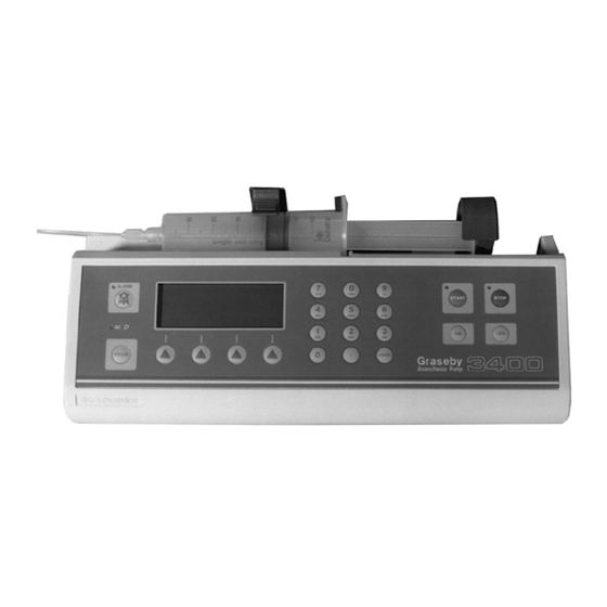
Anaesthesia Syringe Pump
Brand:
SIMS GRASEBY
| Category:
Medical Equipment
| Size: 3 MB
Table of Contents
Table of Contents
4
General
11
Warnings and Caution
11
Abbreviations Used
12
Chapter 1
13
Introduction, Features, Classification and Specification
13
Introduction
14
General Information
14
Front View of the 3400 Pump
15
Features
16
Classification
16
Specification
17
Brief History of Graseby Bedside Syringe Pumps
18
Chapter 2
21
Configuration & Diagnostic Mode, and Thrust Adjustments
21
Configuration Mode
21
Calling up the Configuration Mode
22
Changing an Option
22
Moving to the Next Parameter
22
Syringe Brands
22
Display Language
23
Bolus Beep
23
Preset Bolus Dose
23
Mass Units
23
LCD Contrast
23
Baud Rate
23
Max Rate
23
Diagnostic Mode
24
Calling up the Diagnostic Mode
24
Moving to the Next Parameter
24
Diagnostic Displays
24
Exiting from the Diagnostic Mode
25
Disassembly and Assembly of Casing
25
Taking the Casing Apart
25
Assembly
25
Occlusion Measurements
26
Thrust Measurements
26
Syringe Stiction
26
Thrust Checks
27
Thrust Adjustments
28
Chapter 3
29
Functional Descriptions
29
Introduction
30
Drive System
30
DC Motor and Leadscrew
30
Processor
30
Toggle Mechanism
30
Plunger Clamp
30
Occlusion Sensing System
31
Clutch Assembly and Opto-Sensor
31
Occlusion Detection
31
Electro/Mechanical Control System
31
Motor Speed
31
Motor Rotation
31
Mechanical Characteristics
31
Sensing (Alarm) Systems
32
Introduction
32
Syringe Nearly Empty
32
End of Infusion/Occlusion
32
AC Power Failure
32
Battery Voltage Low
32
Self Tests/Pump Malfunction
32
Drive Disengaged, or Syringe Not Fitted
32
Syringe Sizing System
32
Software
33
Design Methods
33
Self Tests
33
Chapter 4
34
Circuit Descriptions
34
Introduction
35
Main Board Circuit
36
Sub-Circuits
36
Processor Core Circuit
36
Description
36
Motor Interface Circuit Description
37
Introduction
37
Transients; Suppression
37
Motor Speed Control
37
Power Control Circuit
38
Logic Circuit Supply; VCC
38
RAM and Clock Supply
38
Sensors Interface Circuit
38
Introduction
38
Circuit Description
38
RS232 Interface Circuit
39
Circuit Description
39
Input/Output Circuit
39
Front Panel Interface
39
RS232 'D' Connector Connections
39
LED Illumination
40
Real Time Clock
40
Liquid Crystal Display
40
Sounder
40
Regulator Board Circuit
41
Introduction
41
Live Circuit and T1 Primary Description
41
T1 Secondary
41
Batteries Circuit
41
Overvoltage Protection
42
Plug PL11 Outputs
42
Setting RV1
42
Temperature/Voltage Range for Setting RV1
42
Size Sensors and Board
43
Opto Sensors and Board
43
Umbilical Board Connections
43
Umbilical Cable Connector
43
Overall Block Diagram of the 3400 System
44
Main Board Block Diagram
45
Processor Core Circuit Diagram
46
Motor Interface Circuit Diagram
47
Power Control Circuit Diagram
48
Sensors Interface Circuit Diagram
49
Communications (RS232) Circuit Diagram
50
Main Board Input/Output Interface Circuit Diagram
51
Umbilical Cable Connections Diagram
52
Umbilical Board Connections Diagram
53
Regulator Circuit Diagram (Overview)
55
Regulator Live Circuit Diagram
56
Regulator Isolated Circuit Diagram
57
Main Board: Layout of Components
58
Regulator Board: Layout of Components
59
Syringe Size Sensors Circuit Diagram
60
Opto Sensors Circuit Diagram
61
Umbilical Board: Layout of Components
62
Membrane Switch Panel
63
Internal Ribbon Cable and 'D' Connector Connections
64
Chapter 5
65
Fault Codes
65
Cleaning
66
Repair Procedures
68
Removal
71
Renewal
72
Front Case Spares Kit
76
Size Sensor Flag Spares Kit
76
Rear Case Spares Kit
76
Functional Tests
78
Introduction
78
Chapter 6
82
Linear Accuracy
82
General Assembly
84
Pole Clamp Assembly: Non-Rotating
85
General Assembly
86
Chapter 7
89
Plunger Clamp and Half Nut Assemblies
89
Pole Clamp Assembly: Non-Rotating
90
Pole Clamp Assembly: Rotating
91
Leadscrew Assembly
92
Opto Sensors Board Assembly
93
Size Sensors Board Assembly
94
Main Board Assembly
95
Main Board Assembly
96
Regulator Board Assembly
98
Regulator Board Assembly
99
Distribution Board Assembly
100
CHAPTER 8 Syringe Conversion Procedures
102
Programming Procedures
103
Appendix
105
Introduction
105
Warnings
106
Reassembly
107
Setting the Size Sensor Flag
108
Advertisement
Advertisement
Related Products
SIMS GRASEBY MR10
SIMS GRASEBY Categories
Medical Equipment
More SIMS GRASEBY Manuals
Login
Sign In
OR
Sign in with Facebook
Sign in with Google
Upload manual
Upload from disk
Upload from URL