
Related Manuals for SIMS GRASEBY 3400

Summary of Contents for SIMS GRASEBY 3400
- Page 1 Graseby 3400 Anaesthesia Syringe Pump TECHNICAL SERVICE MANUAL Document Number 00SM-0132 Issue 6.0...
- Page 2 All possible care has been taken in the preparation of this publication, but SIMS Graseby Limited accepts no liability for any inaccuracies that may be found. SIMS Graseby reserves the right to make changes without notice both to this publication and to the product which it describes.
- Page 3 SIMS Graseby Ltd. , i i Page ii Issue 6.2 (Feb 01) 3400 Service Manual...
-
Page 4: Table Of Contents
Max rate ..................2-3 Diagnostic mode ................. 2-4 Calling up the Diagnostic mode ........... 2-4 Moving to the next parameter ............2-4 Diagnostic displays ..............2-4 Exiting from the Diagnostic mode ..........2-5 Page iii 3400 Service Manual Issue 6 (July 00) - Page 5 Battery voltage low ..............3-3 Self tests/pump malfunction ............3-3 Drive disengaged, or syringe not fitted ........3-3 Syringe sizing system ..............3-3 Software ....................3-4 Design methods ................3-4 Self tests ..................3-4 Page iv Issue 6 (July 00) 3400 Service Manual...
- Page 6 Plug PL11 outputs ..............4-8 Setting RV1 ................4-8 Size sensors and board ..............4-9 Opto sensors and board ..............4-9 Umbilical board connections ............. 4-9 Umbilical cable connector ..............4-9 Page v 3400 Service Manual Issue 6 (July 00)
- Page 7 Introduction ..................6-1 Plunger clamp alarm checks ............... 6-4 Ramp check procedures .............. 6-4 Linear accuracy ..................6-5 Test procedures ................6-5 Plunger clamp alignment ..............6-5 Test procedures ................6-5 Page vi Issue 6 (July 00) 3400 Service Manual...
- Page 8 Warnings ..................... A-2 Caution ....................A-2 Opening the case ................A-2 Removal of old SSF ................A-2 Reassembly ..................A-3 Final testing ..................A-3 Setting the Size Sensor Flag .............. A-4 Page vii 3400 Service Manual Issue 6 (July 00)
- Page 9 Page Front view of the 3400 pump ............1-2 Thrust measuring set up .............. 2-7 Overall block diagram of the 3400 system ......... 4-10 Main board block diagram ............4-11 Processor core circuit diagram ..........4-12 Motor interface circuit diagram ..........4-13 Power control circuit diagram.............
- Page 10 Leadscrew assembly ..............7-9 Opto sensors board assembly ........... 7-10 Size sensors board assembly ............ 7-11 Main board assembly ..............7-12 Regulator board assembly ............7-15 Distribution board assembly ............7-17 Page ix 3400 Service Manual Issue 6 (July 00)
-
Page 11: General
Warnings and cautions SIMS Graseby Ltd. General This Technical Service Manual (TSM) together with the Instruction Manual for the 3400, contains the information that is required in order to carry out the following actions to the pump: • operation, •... -
Page 12: Abbreviations Used
Light Emitting Diode Manually Controlled Infusion Milliampere Milligram Millilitre Millimetre Patient Controlled Analgesia Printed Circuit Board Plug Pulse Width Modulation Prefilled syringe Resistor R.F. Radio Frequency Random Access Memory Read Only Memory Volts Page xi 3400 Service Manual Issue 6 (July 00) -
Page 13: Introduction, Features, Classification And Specification
CHAPTER 1 INTRODUCTION, FEATURES, CLASSIFICATION AND SPECIFICATION 3400 ANAESTHESIA SYRINGE PUMP... -
Page 14: Introduction
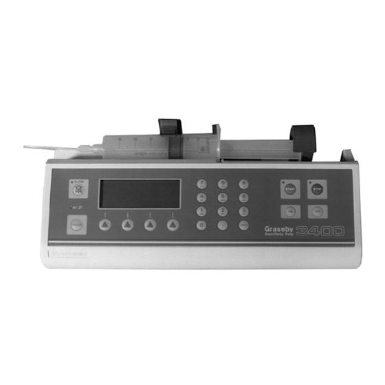
INTRODUCTION, FEATURES, CLASSIFICATION AND SPECIFICATION Introduction The 3400 anaesthesia syringe pump (Fig. 1.1) is based on a micro-controller design and has been purpose developed by Graseby for the administration of anaesthetics, mainly in a hospital operating theatre. The pump allows a Manually Controlled Infusion, and/or a bolus to be infused using the normal brands of syringe. -
Page 15: Front View Of The 3400 Pump
SIMS Graseby Ltd. Figure 1.1 Front view of the 3400 pump 1 — 2 Issue 6 (July 00) 3400 Service Manual... -
Page 16: Features
Nearly Empty alarm; etc., • designed in consultation with users. Classification The following classification information applies to the 3400, and is to the IEC 601-1:1988 requirement. Insulation The pump is a Class II (double insulated) device. Also classified as internally powered equipment. -
Page 17: Specification
Specification SIMS Graseby Ltd. Graseby pumps are subject to continual development and the 3400 may, therefore, differ Specification slightly from the following specification: Dimensions: 325 mm (long) x 195 mm (high) x 115 mm (deep) with the pole clamp fitted and the plunger clamp closed. -
Page 18: Brief History Of Graseby Bedside Syringe Pumps
A larger liquid crystal display was used on the 3400 with the ability to display text in different sizes, also ‘soft-keys’ were used to make the user interface simpler. The range of syringe sizes that could be used was also increased. For more advanced applications the pump could be controlled by a computer. - Page 19 A large text vacuum fluorescent display was added, and the increased syringe size range of the 3400 remained. A DC input supply (10 V to 28 V DC) version of the 3200 is also manufactured by SIMS Graseby. This variant is primarily intended for use in an aviation environment.
- Page 20 CHAPTER 2 CONFIGURATION & DIAGNOSTICS MODE, AND THRUST ADJUSTMENTS 3400 ANAESTHESIA SYRINGE PUMP...
-
Page 21: Configuration & Diagnostic Mode, And Thrust Adjustments
WARNING The Configuration Mode must only be used by personnel who have been appropriately trained in using the 3400. The Configuration mode allows various parameters to be made available, which in turn allows various settings within these parameters to be set to the values required for the infusion. -
Page 22: Calling Up The Configuration Mode
1. Options: BD Plastipak Terumo Braun Omnifix Monoject IMS Pump-jet 30 Injectomat 50 ml Braun Perfusor: a conversion kit is required, see Chapter 8. 2 — 2 Issue 6 (July 00) 3400 Service Manual... -
Page 23: Display Language
(up to 400 ml/h) and the bolus infusion (up to 1200 ml/h). Table 2.1 Syringe size and maximum automatic continuous infusion rate Syringe size Max. auto. cont. infusion rate (ml/h) 50/60 30/35 3400 Service Manual Issue 6 (July 00) 2 — 3... -
Page 24: Diagnostic Mode
Diagnostic The Diagnostic mode must only be used by appropriately qualified personnel. mode The 3400 has been designed so that the Diagnostic mode parameters will only be available if a set sequence of pump buttons are pressed. Calling up With the AC power connected and switched on (or under internal battery power) press the the Diagnostic ON button. -
Page 25: Exiting From The Diagnostic Mode
The screws should be tightened to a torque of between 70 and 75 cNm, and in the order shown in the diagram below: GM0595-B 3400 Service Manual Issue 6 (July 00) 2 — 5... -
Page 26: Occlusion Measurements
The thrust of a particular pump may, therefore, differ from the original factory set level. The occlusion thrust of the 3400 pump is factory set at Graseby’s to be between 5.7 kg and 6.2 kg (767 mmHg and 834 mmHg). -
Page 27: Thrust Checks
The thrust checks that are detailed below use the weights that correspond to the factory set Thrust checks occlusion threshold levels for a 3400 (i.e. 5.7 and 6.2 kg). If a different occlusion level setting is required then the weights will have to be adjusted accordingly. The thrust adjustment procedures are detailed on page 2-8. -
Page 28: Thrust Adjustments
In order to obtain the thrust required it may be necessary to repeat steps 2 to 7 above. Finalise the assembly of the pump casing (see page 2-5). 10. Carry out tests No 9 and 10 detailed in the functional test procedures (see page 6-3). 2 — 8 Issue 6 (July 00) 3400 Service Manual... -
Page 29: Functional Descriptions
CHAPTER 3 FUNCTIONAL DESCRIPTIONS 3400 ANAESTHESIA SYRINGE PUMP... -
Page 30: Introduction
FUNCTIONAL DESCRIPTIONS Introduction This Chapter explains how the 3400 operates. Reading this chapter will help a technician to rectify any possible faults that may occur within the pump. The functional descriptions of the pump may be divided into five separate areas, and each... -
Page 31: Occlusion Sensing System
Mechanical The mechanical characteristics of the system are: characteristics • Gearbox reduction ratio: 150:1. • Leadscrew pitch: 1.587 mm. • Syringe characteristic: 1 ml/1.8 mm (BD 60 ml syringe). 3 — 2 3400 Service Manual Issue 6 (July 00) -
Page 32: Sensing (Alarm) Systems
Introduction In addition to the occlusion sensing system (see page 3-2) the following sensing systems are also operative within the 3400. Syringe A metal flag protrudes from the left hand side of the half nut (in parallel with the leadscrew), nearly empty this is the nearly empty flag. -
Page 33: Software
ROM test (16 bit CRC). • RAM test. • Power supply voltage test. • Keyboard test. This test checks for shorted keys. The pump’s settings are stored in EEPROM in the processor. 3 — 4 3400 Service Manual Issue 6 (July 00) -
Page 34: Circuit Descriptions
CHAPTER 4 CIRCUIT DESCRIPTIONS 3400 ANAESTHESIA SYRINGE PUMP... -
Page 35: Introduction
CHAPTER 4 CIRCUIT DESCRIPTIONS Introduction This Chapter describes the action of the circuits that are used to operate the 3400 and also shows the associated circuit diagrams and circuit board layouts. The 3400 contains five separate circuit boards, as follows: •... -
Page 36: Main Board Circuit
IC9 for its operating software. Pins 44 and 43 on IC12 are held at Vcc and ground (respectively) as the reference inputs to the processor’s built in A to D converter. 4 — 2 Issue 6 (July 00) 3400 Service Manual... -
Page 37: Motor Interface Circuit Description
IC12 will change the duty cycle of the PWM output. By using this feedback system the speed of the motor can be closely controlled to within set limits. 3400 Service Manual Issue 6 (July 00) 4 — 3... -
Page 38: Power Control Circuit
Vcc’, of 3 V. Sensors interface circuit Introduction The six opto-sensors (Fig. 4.16 and 4.18) used in the 3400 are multiplexed onto three lines into the processor and are used to carry out sensing functions that include the following: •... -
Page 39: Rs232 Interface Circuit
The four columns of the matrix, pins 9 to 12 on PL2 (inclusive), are connected to IC1, the parallel out serial register. As each column is pulled low , the status of each button in that column is input to the processor. 3400 Service Manual Issue 6 (July 00) 4 — 5... -
Page 40: Led Illumination
Q4 and the associated components C3, R6, R12 and R17 constitute a low pass filter which allows the PWM signal (SOUND) from the processor, to activate the sounder. The sounder is connected to plug PL1. 4 — 6 Issue 6 (July 00) 3400 Service Manual... -
Page 41: Regulator Board Circuit
SIMS Graseby Ltd. Regulator board Regulator board circuit The 3400 utilizes a primary switching power supply, as shown on Figures 4.11, 4.12 and Introduction 4.13, thus allowing the pump to operate with an AC input voltage between 100 V and 250 V. -
Page 42: Overvoltage Protection
Table 4.2 Temperature/voltage range for setting RV1 Ambient temperature DC output voltage (°c) (68 ohm load) 7.015 7.027 7.038 7.050 7.062 7.073 7.085 7.096 7.108 7.120 7.131 7.143 7.154 7.166 4 — 8 Issue 6 (July 00) 3400 Service Manual... -
Page 43: Size Sensors And Board
This method of design means that only the ribbon cable and the batteries connector link the two case halves, thus facilitating, when required, ease of servicing. 3400 Service Manual Issue 6 (July 00) 4 — 9... -
Page 44: Overall Block Diagram Of The 3400 System
Overall block diagram SIMS Graseby Ltd. Figure 4.1 Overall block diagram of the 3400 system 4 — 10 Issue 6 (July 00) 3400 Service Manual... -
Page 45: Main Board Block Diagram
SIMS Graseby Ltd. Main board block diagram Figure 4.2 Main board block diagram 3400 Service Manual Issue 6 (July 00) 4 — 11... -
Page 46: Processor Core Circuit Diagram
PG1/XA14 KEYBOARD5 PG2/XA15 VCC' PG3/XA16 IC15B PG4/XA17 PG5/XA18 62256 SCLK 32.768KHz PG7/RW TCI_MODULE_BYPASS IC15C DS1202S IO_CLK IC15E IO_DATA IO_CLR MC68HC11K1FN R65D POWER_OFF 10K# GM0324-A Figure 4.3 Processor core circuit diagram 4 — 12 3400 Service Manual Issue 6 (July 00) -
Page 47: Motor Interface Circuit Diagram
SIMS Graseby Ltd. Motor interface Figure 4.4 Motor interface circuit diagram 3400 Service Manual Issue 6 (July 00) 4 — 13... -
Page 48: Power Control Circuit Diagram
Power control SIMS Graseby Ltd. Figure 4.5 Power control circuit diagram 4 — 14 3400 Service Manual Issue 6 (July 00) -
Page 49: Sensors Interface Circuit Diagram
SIMS Graseby Ltd. Sensors interface Figure 4.6 Sensors interface circuit diagram 3400 Service Manual Issue 6 (July 00) 4 — 15... -
Page 50: Communications (Rs232) Circuit Diagram
Communications (RS232) SIMS Graseby Ltd. Figure 4.7 Communications (RS232) circuit diagram 4 — 16 3400 Service Manual Issue 6 (July 00) -
Page 51: Main Board Input/Output Interface Circuit Diagram
SIMS Graseby Ltd. Main board input/output Figure 4.8 Main board input/output interface circuit diagram 3400 Service Manual Issue 6 (July 00) 4 — 17... -
Page 52: Umbilical Cable Connections Diagram
SIMS Graseby Ltd. Figure 4.9 Umbilical cable connections diagram 4 — 18 3400 Service Manual Issue 6 (July 00) -
Page 53: Umbilical Board Connections Diagram
UM17 OPT1 SIZE UM15 OPT2 SENSORS UM18 OPTDRV1 HEADER 6 SER_GND UM10 SERIAL UM16 PORT POWER SUPPLY UM14 UM12 HEADER 4 HEADER 5X2 GM0332-A Figure 4.10 Umbilical board connections diagram 3400 Service Manual Issue 6 (July 00) 4 — 19... - Page 54 SIMS Graseby Ltd. 4 — 20 3400 Service Manual Issue 6 (July 00)
-
Page 55: Regulator Circuit Diagram (Overview)
SIMS Graseby Ltd. Regulator circuit Figure 4.11 Regulator circuit diagram (overview) 3400 Service Manual Issue 6 (July 00) 4 — 21... -
Page 56: Regulator Live Circuit Diagram
COMSIG OUT2 BUZ80 COMP 10nF SENSE 470R VREF OSC1 COMSIG 330K OSC2 COMSIG BIAS SHUTDN DISCH RESET SCREEN1 HV9120P 390K COMPWR COMPWR GM0334-A COMSIG Figure 4.12 Regulator live circuit diagram 4 — 22 3400 Service Manual Issue 6 (July 00) -
Page 57: Regulator Isolated Circuit Diagram
BATT+ 2 Amp 1K5 TH 3K6 1% 220R TL431 470R 220R 2K2 1% TIC106B BC184L 2.2µF/50V 1000µF ESD GND SCREEN2 ESD GND BATT– GM0335-A Figure 4.13 Regulator isolated circuit diagram 3400 Service Manual Issue 6 (July 00) 4 — 23... -
Page 58: Main Board: Layout Of Components
Main board components SIMS Graseby Ltd. Figure 4.14 Main board: layout of components 4 — 24 3400 Service Manual Issue 6 (July 00) -
Page 59: Regulator Board: Layout Of Components
SIMS Graseby Ltd. Regulator board components 3000 SERIES PSU 130-013 ISS. PL11 GM0337-A Figure 4.15 Regulator board: layout of components 3400 Service Manual Issue 6 (July 00) 4 — 25... -
Page 60: Syringe Size Sensors Circuit Diagram
Syringe size sensors board SIMS Graseby Ltd. OPT1 SIZE SENSOR B GM0338-A Figure 4.16 Syringe size sensors circuit diagram GM0339-A Figure 4.17 Syringe size sensors board: layout of components 4 — 26 Issue 6 (July 00) 3400 Service Manual... -
Page 61: Opto Sensors Circuit Diagram
OPTO2 DRIVE ENGAGEMENT DETECTOR Note: Cableform is hardwired CHOKE GM0340-A Figure 4.18 Opto sensors circuit diagram OPTO0 OPTO1 128-090 OPTO2 ISS. GM0341-A Figure 4.19 Opto sensors board: layout of components 3400 Service Manual Issue 6 (July 00) 4 — 27... -
Page 62: Umbilical Board: Layout Of Components
Distribution board components SIMS Graseby Ltd. Figure 4.20 Umbilical board: layout of components 4 — 28 Issue 6 (July 00) 3400 Service Manual... -
Page 63: Membrane Switch Panel
SIMS Graseby Ltd. Membrane switch panel SEL1 SEL2 SEL0 SEL3 BOLUS START ALARM STOP CANCEL GM0343-A Figure 4.21 Membrane switch panel circuit 3400 Service Manual Issue 6 (July 00) 4 — 29... -
Page 64: Internal Ribbon Cable And 'D' Connector Connections
Internal ribbon cable SIMS Graseby Ltd. Figure 4.22 Internal ribbon cable and ‘D’ connector connections 4 — 30 Issue 6 (July 00) 3400 Service Manual... -
Page 65: Fault Codes
CHAPTER 5 FAULT CODES, CLEANING AND REPAIR PROCEDURES 3400 ANAESTHESIA SYRINGE PUMP... -
Page 66: Cleaning
FAULT CODES, CLEANING AND REPAIRS Fault codes Comprehensive fault codes have been designed into the 3400 so that should a fault occur it can easily be identified. The Fault code numbers are used to indicate the type of fault that has occurred. - Page 67 External interference... Check communication link and (Comms.) fault. e.g. static interference interface cable. or R.F. interference. Circuit fault. Return to SIMS Graseby. Internal fault. External interference... Relocate the pump. e.g. static interference or R.F. interference. Circuit fault. Return to SIMS Graseby.
-
Page 68: Repair Procedures
Cleaning CAUTION The 3400 must not be immersed in any liquids. Immediately wipe off any liquid that may be spilt on the pump. The outer surfaces of the pump can be cleaned by wiping them over with a damp cloth (a dilution of soapy water may be used if necessary). - Page 69 Once the required access has been obtained and the repair carried out the tray can be refitted by replacing the fixing screw, and the casing closed as detailed on page 2-5. 5 — 4 Issue 6 (July 00) 3400 Service Manual...
- Page 70 (see Fig. 7.1 and 7.2). Remove and retain the two brackets. Carefully easing out the flag from its housing, lift up the square lay shaft and toggle mechanism. (contd.) Issue 6 (July 00) 5 — 5 3400 Service Manual...
-
Page 71: Removal
The motor and gearbox are coupled to the right hand end of the leadscrew assembly. Uncouple the leadscrew assembly from the gearbox by pulling it away from the gear box shaft. 5 — 6 Issue 6 (July 00) 3400 Service Manual... -
Page 72: Renewal
Fit a new clutch and disc assembly by reversing steps 2 to 4 detailed above, and then assemble the casing as detailed on page 2-5. Carry out the thrust checks and plunger clamp checks/adjustments as detailed on page 2-7 and 6-3 respectively. Issue 6 (July 00) 5 — 7 3400 Service Manual... - Page 73 Assemble the casing as detailed on page 2-5. Super nut Early 3400 pump's were fitted with a half nut, and in May 1999 the half nut was replaced with renewal a three-quarter super nut. The following procedures only make reference to the presently installed super nut, which is a direct replacement for the original half nut.
- Page 74 Fit a new sensor board by reversing steps 2 to 6 detailed above, and then close the casing as detailed on page 2-5. Carry out the syringe size sensors tests as detailed on page 6-1. Issue 6 (July 00) 5 — 9 3400 Service Manual...
- Page 75 If an old style front or rear case becomes damaged and requires replacing then the appropriate repair kit is available from SIMS Graseby. There are two kits (front or rear case) which each contain all the necessary instructions and parts to carry out a repair.
-
Page 76: Front Case Spares Kit
Case screws (6 off) 5001-0345 M4x12 pozi pan These items may be obtained individually. Note: The Case rear label will be Country dependent, and can be supplied, e.g. 0132-0091 240 V English Issue 6 (July 00) 5 — 11 3400 Service Manual... - Page 77 CHAPTER 6 FUNCTIONAL TESTS 3400 ANAESTHESIA SYRINGE PUMP...
-
Page 78: Functional Tests
Syringe size 60 displayed Note: SIMS Graseby manufacture a set of 18 Syringe Size Sensor gauges (Part No. 0131-0202, see Appendix page A-5). The SIMS Graseby Customer Care Department is able to take orders for these gauges and will supply the current price. This set of gauges enables test No. - Page 79 Infusion Check that the infusion rate The displayed rate of infusion rate. can be changed changes. (see Instruction Manual). Press STOP. The pump changes to its set-up mode. (contd.) Issue 6 (July 00) 6 — 2 3400 Service Manual...
- Page 80 ... START the pump. ENDED (KVO=.5) appears. Note: When carrying out test No. 11(ii) on a Perfusor pump ensure that the syringe is set to a minimum of 18 ml. 3400 Service Manual Issue 6 (July 00) 6 — 3...
- Page 81 3. Two new thicker washers (Part No. 5014-3020) in place of the previously fitted thinner washers on the status sensors board. New square style flag Old ramp style flag Notch New style plate GM1087-A Issue 6 (July 00) 6 — 4 3400 Service Manual...
-
Page 82: Linear Accuracy
Run the pump for 5 seconds. Using the taper gauge check that the front edge of the plunger clamp is between 8.0 mm and 10 .0 mm above the surface of the case. 3400 Service Manual Issue 6 (July 00) 6 — 5... - Page 83 CHAPTER 7 ILLUSTRATED PARTS LIST 3400 ANAESTHESIA SYRINGE PUMP...
-
Page 84: General Assembly
3400 Illustrated Parts List SIMS Graseby Ltd. CHAPTER 7 ILLUSTRATED PARTS LISTS Figure 7.1 General assembly Item Description Part number Remarks Model 3400 English 0132-0001 110 V model 0132-0701 German 0132-0707 Zeneca 0132-0710 German Perfusor 0132-0714 English with Euro mains plug... -
Page 85: Pole Clamp Assembly: Non-Rotating
SIMS Graseby Ltd. 3400 Illustrated Parts List Figure 7.1 General assembly (contd) Item Description Part number Remarks Case screws 5001-0345 6 required Motor and gearbox assembly 0132-0015 Leadscrew assembly 0132-0086 See Fig. 7.4 Occlusion sensing assembly 0131-0067 Support tube 0127-0047 Plunger clamp assembly See Fig. -
Page 86: General Assembly
Sims Graseby Ltd. 3400 IPL Figure 7.1 General assembly 3400 Service Manual 7 — 3 Issue 6 (July 00) - Page 87 SIMS Graseby Ltd. 3400 Illustrated Parts List 7 — 4 Issue 6 (July 00) 3400 Service Manual...
- Page 88 3400 Illustrated Parts List SIMS Graseby Ltd. Figure 7.1 General assembly (contd) Item Description Part number Remarks — Technical service manual 00SM-0132 Not illustrated — Size sensor gauge set 0131-0202 Not illustrated Kit contains the following items: 18 size sensor gauges.
-
Page 89: Plunger Clamp And Half Nut Assemblies
SIMS Graseby Ltd. 3400 Illustrated Parts List Figure 7.2 Plunger clamp and half nut assemblies Item Description Part number Remarks Plunger clamp and half nut assemblies Plunger clamp and tube 0127-0044 Plunger clamp cover and internal kit 0131-0239 Kit contains the following items: Plunger clamp cover, Plunger clamp lock,... -
Page 90: Pole Clamp Assembly: Non-Rotating
3400 Illustrated Parts List SIMS Graseby Ltd. Fig. 7.3a Pole clamp assembly: non-rotating Item Description Part number Remarks Pole clamp assembly (new version) 0131-0129 See Fig. 7.3a GM0800-A Figure 7.3a Pole clamp assembly - Non-rotating 3400 Service Manual Issue 6 (July 00) -
Page 91: Pole Clamp Assembly: Rotating
SIMS Graseby Ltd. 3400 Illustrated Parts List Fig. 7.3b Pole clamp assembly: rotating Item Description Part No. Remarks Rotating pole clamp assembly 0131-0083 Securing plate 0131-0074 Locating ring 0127-0064 Handle 0127-0060 Crescent circlip 5030-5710 External circlip type 7100-010 5030-4010 Spirol pin 3 x 26... -
Page 92: Leadscrew Assembly
3400 Illustrated Parts List SIMS Graseby Ltd. Figure 7.4 Leadscrew assembly Item Description Part number Remarks Leadscrew sub assembly 0132-0086 Leadscrew coupling 0127-0074 Figure 7.4 Leadscrew assembly 3400 Service Manual Issue 6 (July 00) 7 — 9... -
Page 93: Opto Sensors Board Assembly
SIMS Graseby Ltd. 3400 Illustrated Parts List Figure 7.5 Opto sensors board assembly Item Description Part number Remarks Opto sensors board assembly 0128-0090 Note: The items below are for reference only and are not available as spare parts Opto interrupter HOA 0875-051... -
Page 94: Size Sensors Board Assembly
3400 Illustrated Parts List SIMS Graseby Ltd. Figure 7.6 Size sensors board assembly Item Description Part number Remarks Size sensors board assembly 0130-0017 Note: The items below are for reference only and are not available as spare parts Size sensor moulding... -
Page 95: Main Board Assembly
SIMS Graseby Ltd. 3400 Illustrated Parts List Figure 7.7 Main board assembly Item Description Part number Remarks Main board assembly 0132-0011 Sounder 3430-1205 Sounder restraint kit 0131-0240 Kit contains the following items: Nut M3 - 2 off, screw M3 x 16 - 2 off, Pillar - 2 off... -
Page 96: Main Board Assembly
3400 Illustrated Parts List SIMS Graseby Ltd. R46 R44 GM0237-B Figure 7.7 Main board assembly 3400 Service Manual Issue 6 (July 00) 7 — 13... - Page 97 SIMS Graseby Ltd. 3400 Illustrated Parts List Figure 7.7 Main board assembly (contd) Item Description Part number Remarks R01 to R04, R27, R29, R30, R32, R39, R45, R46, R50, R55 to R60, R64 and R66, Resistor, 10K, 5%, 1/8 W, 20 off...
-
Page 98: Regulator Board Assembly
3400 Illustrated Parts List SIMS Graseby Ltd. Figure 7.8 Regulator board assembly - AC Power Item Description Part number Remarks Regulator board assembly 0128-0013 Fuse cover 3412-0228 FS1, Fuse 500 mA 5 x 20 mm, 3410-3705 UL-BUSSMANN S500 FS2, Fuse 1A 5 x 20 mm... -
Page 99: Regulator Board Assembly
SIMS Graseby Ltd. 3400 Illustrated Parts List Figure 7.8 Regulator board assembly - AC power (contd) Item Description Part number Remarks R13, Res 390K 5% 1/8 W R14, Res 330K 5% 1/8W R15, R19, R25, Res 4K7 5% 1/8 W - 3 off... -
Page 100: Distribution Board Assembly
3400 Illustrated Parts List SIMS Graseby Ltd. Figure 7.9 Distribution board assembly Item Description Part number Remarks Distribution board assembly 0132-0016 Note: The following items are for reference only and are not available for spare parts Connector INC 26 way... - Page 101 CHAPTER 8 BRAUN PERFUSOR CONVERSION 3400 ANAESTHESIA SYRINGE PUMP...
-
Page 102: Syringe Conversion Procedures
Syringe conversion procedures Introduction The 3400 can easily be converted, if required, in order to use the ‘Braun Perfusor 50 ml syringe’. The Perfusor conversion kit part number is 0131-0048. The conversion procedures are detailed below and are shown in Figure 8.1. -
Page 103: Programming Procedures
Set the pump to the brand of syringe that is going to be used and then press the STOP button in preparation for the next infusion. Figure 8.1 Braun Perfusor conversion: parts required 8 — 2 Issue 6 (July 00) 3400 Service Manual... - Page 104 APPENDIX FITMENT OF NEW MODIFIED SIZE SENZOR FLAG 3400 ANAESTHESIA SYRINGE PUMP...
-
Page 105: Introduction
The SSF and shims etc. that will be required to modify a 3400 pump are supplied in kit form (part No. 0137-0025), and this spares kit will include the following: •... -
Page 106: Warnings
SIMS Graseby Ltd. WARNINGS When a new SSF has been fitted to a 3400 pump, the pump must be tested using the Syringe Size Sensor gauges (Part No. 0131- 0202) available from SIMS Graseby. Page 3 gives details of the Final Testing procedures. -
Page 107: Reassembly
1.4 mm. If necessary, use a combination of shims to obtain the thickness required, up to a maximum of 2.4 mm. During production at SIMS Graseby a 1.6 mm shim is initially fitted. Using the modified SSF, reassemble in reverse order to that given in 1 to 6 above, all the components that were disassembled. -
Page 108: Setting The Size Sensor Flag
SIMS Graseby Ltd. SETTING THE SIZE SENSOR FLAG 1. Using the 3400 size sensor test gauges (see page 5) place the 20 ml minimum gauge (Part No. 131-170) into the pump's cradle. 2. If necessary rotate the adjustment screw until 20 appears on the display, and then rotate the adjustment screw counter-clockwise until 10 appears on the display. - Page 109 Appendix The SIMS Graseby Size Sensor Gauge set (Part No. 0131-0202) contains the gauges that are used to carry out the Size Sensor tests on the 3400. These gauges are listed below: 3400 Syringe Size Sensor Gauges (white) PART No.
- Page 110 IN AN EMERGENCY CONTACT: SIMS Graseby Limited Colonial Way, Watford, Herts , UK, WD2 4LG Tel: (+44) (0)1923 246434 Fax: (+44) (0)1923 231595 Web: www.graseby.co.uk Part No. 00SM-0132 Issue 6 July 2000 © SIMS Graseby Ltd. 2000 PRINTED ON RECYCLED PAPER...
Need help?
Do you have a question about the 3400 and is the answer not in the manual?
Questions and answers