Sign In
Upload
Manuals
Brands
Sierra Monitor Corporation Manuals
Measuring Instruments
5100-88-IT
Sierra Monitor Corporation 5100-88-IT Manuals
Manuals and User Guides for Sierra Monitor Corporation 5100-88-IT. We have
1
Sierra Monitor Corporation 5100-88-IT manual available for free PDF download: Manual
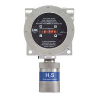
Sierra Monitor Corporation 5100-88-IT Manual (62 pages)
5100-**-IT series. Toxic Gas Sensor Module
Brand:
Sierra Monitor Corporation
| Category:
Measuring Instruments
| Size: 3 MB
Table of Contents
Table of Contents
4
Table of Contents
7
Product Description
7
General
7
Modes of Operation
8
Analog Operation
8
Modbus Operation
8
Remote Sensor
8
Sentry Interface
8
HART Connection
9
Optional Integral Relays
9
Remote Alarm Reset
9
Product Configuration
8
Theory of Operation
8
List of Figures
9
Mechanical
9
Enclosure
9
Figure 1: Model 5100-XX-IT Toxic Gas Sensor Module - Mounting Options
9
Figure 2: Model 5100-05-IT-S1/S2 Toxic Gas Sensor - Stainless Steel Enclosure, Dimensions
10
Figure 3: Model 5100-05-IT-A1/A2 Toxic Gas Sensor - Cast Aluminum Enclosure, Dimensions
10
Sensor Assembly
11
Transmitter Electronics
11
Interconnect Wiring
11
Power Requirements
11
Cautions & Warnings
12
Calibration Frequency
12
Quick Start
13
Gas Sensor Modules - General
12
Introduction
12
Wiring Warnings
12
Module Installation
13
Overview
13
Transmitter Installation
13
Wiring
13
Startup and Operation
14
Zero Stabilization
14
Installation
15
Figure 4: Specific Gravities
15
Figure 5: Typical Mounting Options
15
Sensor Module Locations
15
Wiring
16
4.2.2.1 Termination Resistor Jumpers
16
Analog 4-20 Ma Operation
16
Bias Jumpers (BIAS A, BIAS B)
16
Modbus Operation Using RS-485 Connection
16
Sentry Operation Using Sentry Connection
16
General
17
Enclosure Installation
17
Figure 6: Minimum Wire Gauges
17
Transmitter and Sensor Installation
18
Figure 7: Sensor Module Address Switch Positions
19
Figure 8: Transmitter Face Plate
19
Module Address Switch
19
Figure 10: RS-485 - Termination, BIAS Jumper
20
Figure 9: Interface Board Connectors
20
Figure 11: Ma Circuit Types
21
Figure 12: 4-20 Ma Circuit Type Connections for 5100-XX-IT
22
Figure 13: Wiring Connections for Modbus and Sentry Interface
23
Figure 14: Wiring Connections for Remote Alarm Reset
24
Operation
25
Data Entry Keypad
25
Figure 15: Face Plate with Operator Keypad
25
Introduction
25
Figure 16: Master Menu
26
Figure 17: Operation Display Values
26
Main Menu
26
Set-Up
27
Figure 18: Set-Up Configuration Part 1
28
Figure 19: Set-Up Configuration Part 2
29
Figure 20: Maintenance Menu
29
Calibration
30
Maintenance Sub-Menu
29
Calibration Frequency
30
Calibration Gas Delivery Methods
30
Calibration Preparation
30
Figure 21: Model 5358-01 Calibration Adapter
30
Sensor Exposure to Gas
31
Calibration Sub-Menu
32
Figure 22: Calibration Sub-Menu
32
5100-03-IT Oxygen Deficiency
33
5100-88-IT Carbon Dioxide
33
Appendix A. Service
34
Appendix A.1. Sensor Module Configuration
34
Appendix A.2. Enclosure Replacement
34
Figure 23: Module Components
34
Appendix A.3. Transmitter Replacement
35
Appendix A.4. Sensor Replacement
35
Appendix A.6.2. Module Displays "Starting" for more than 1 Hour
36
Appendix A.5. Installation Inspection
36
Appendix A.5.1. Controller Installation
36
Appendix A.5.2. Cabling Installation
36
Appendix A.5.3. Sensor Module Installation
36
Appendix A.5.4. Moisture Traps and Rainshields
36
Appendix A.5.5. Standard Voltages
36
Appendix A.6. Inspection and Troubleshooting Guide
36
Appendix A.6.1. Ir Module Does Not Respond to Gas
36
Appendix A.6.6. Display Shows "H" or "L
37
Appendix A.6.9. Display Shows "S" - Sentry Connection
37
Appendix A.6.7. Display Shows "M" - Not Calibrated
37
Appendix A.6.8. Display Shows "C" - Calibration Mode
37
Appendix A.6.5. Module Shows "***Calibration Required
37
Appendix A.6.3. Module Does Not Display the Correct %PPM
37
Appendix A.6.4. Display Shows 'F' - Sensor Missing or Bad Sensor
37
Appendix A.6.10. Diagnostic Leds
37
Appendix B. Specifications
38
Appendix C. Model Numbers and Parts List
41
Appendix D. Limited 2 Year Warranty
42
Appendix E. Remote Sensor Drawing
43
Figure 24: Remote Sensor Drawing
43
Appendix F. Modbus Memory Map
44
Appendix G. HART
45
Figure 25: Wiring Connections Table
45
Figure 26: 4-20 Ma Circuits Types 5100-XX-IT - Connections - HART
46
Appendix H. Gas Sensor Module Calibration
52
Appendix H.1. Calibration for 5100-25-IT
52
Figure 27: Electrolyte Replacement
52
Figure 28: Sensor Assembly - Exploded View
54
Figure 29: Model 5100-25-IT-A1/A2 and Model 5100-26-IT-A1/A2
55
Figure 30: Model 5100-25-IT-S1 and Model 5100-26-IT-S1
55
Appendix H.2. Calibration for 5100-26-IT
56
Appendix I. 5100-88-IT Dimensions
57
Figure 31: Model 5100-88-IT-A1 Dimensions
57
Appendix J. 5100-05-IT FM Performance Approval
58
Appendix K. 5100-XX-IT SIL-2 Certificates
60
Appendix L. 5100-05-IT ATEX Certificate
60
Advertisement
Advertisement
Related Products
Sierra Monitor Corporation 5100-21-IT
Sierra Monitor Corporation 5100-03-IT
Sierra Monitor Corporation 5100-05-IT
Sierra Monitor Corporation 5100-06-IT
Sierra Monitor Corporation 5100-02-IT
Sierra Monitor Corporation 5100-08-IT
Sierra Monitor Corporation 5100-10-IT
Sierra Monitor Corporation 5100-12-IT
Sierra Monitor Corporation 5100-25-IT
Sierra Monitor Corporation 5100-26-IT
Sierra Monitor Corporation Categories
Carbon Monoxide Alarm
Accessories
Measuring Instruments
Security Sensors
Controller
More Sierra Monitor Corporation Manuals
Login
Sign In
OR
Sign in with Facebook
Sign in with Google
Upload manual
Upload from disk
Upload from URL