Table of Contents
Advertisement
Quick Links
Toxic Gas Sensor Module
Effective for all systems manufactured after May 2017.
5100-03-IT
5100-04-IT
5100-10-IT
5100-12-IT
Model 5100-XX-IT
IT Series
APPLICABILITY & EFFECTIVITY
5100-05-IT (FM Approved)
5100-21-IT
5100-25-IT
5100-06-IT
5100-08-IT
5100-26-IT
5100-88-IT
Manual # T12020
Document Revision: D4
Advertisement
Table of Contents

Subscribe to Our Youtube Channel
Related Manuals for Sierra Monitor Corporation 5100-03-IT


Summary of Contents for Sierra Monitor Corporation 5100-03-IT
- Page 1 Model 5100-XX-IT IT Series Toxic Gas Sensor Module APPLICABILITY & EFFECTIVITY Effective for all systems manufactured after May 2017. 5100-03-IT 5100-04-IT 5100-05-IT (FM Approved) 5100-06-IT 5100-08-IT 5100-10-IT 5100-12-IT 5100-21-IT 5100-25-IT 5100-26-IT 5100-88-IT Manual # T12020 Document Revision: D4...
- Page 2 This manual contains information regarding technology that is protected under one or more issued or pending United States and foreign patents. Sierra Monitor and Sentry IT are trademarks of Sierra Monitor Corporation. All other trademarks are the property of their respective owners.
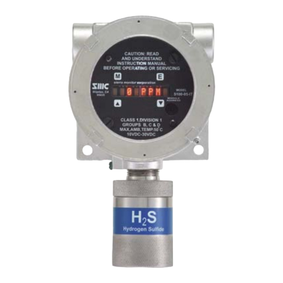
- Page 3 Model 5100-XX-IT Toxic Gas Sensor Module FM PERFORMANCE APPROVAL ONLY THE FOLLOWING ITEMS, FUNCTIONS AND OPTIONS ARE FM* APPROVED Model 5100-05-IT Hydrogen Sulfide Gas Sensor Module Sensor Module Model 5100-05-IT Sensor Module - Hydrogen Sulfide Calibration Equipment Model 1250-01 Gas Sensor Calibration Kit, Type A Model 1260-05 Hydrogen Sulfide in N2, 25 ppm Gas Cylinder Model 1260-45...
-
Page 4: Table Of Contents
Model 5100-XX-IT Toxic Gas Sensor Module TABLE OF CONTENTS Product Description ........................7 General ................................. 7 Product Configuration ..........................8 Theory of Operation ............................. 8 Modes of Operation ............................8 1.4.1 Sentry Interface ............................. 8 1.4.2 Modbus Operation ..........................8 1.4.3 Analog Operation .......................... - Page 5 Model 5100-XX-IT Toxic Gas Sensor Module Sensor Exposure to Gas ..........................31 Calibration Sub-Menu ..........................32 6.5.1 5100-03-IT Oxygen Deficiency ......................33 6.5.2 5100-88-IT Carbon Dioxide......................... 33 Appendix A. Service .......................... 34 Appendix A.1. Sensor Module Configuration ......................34 Appendix A.2. Enclosure Replacement ........................ 34 Appendix A.3.
- Page 6 Model 5100-XX-IT Toxic Gas Sensor Module LIST OF FIGURES Figure 1: Model 5100-XX-IT Toxic Gas Sensor Module – Mounting Options ............9 Figure 2: Model 5100-05-IT-S1/S2 Toxic Gas Sensor – Stainless Steel Enclosure, Dimensions ......10 Figure 3: Model 5100-05-IT-A1/A2 Toxic Gas Sensor – Cast Aluminum Enclosure, Dimensions ......10 Figure 4: Specific Gravities ............................
-
Page 7: Product Description
ATEX Approval (5100-05-IT) The 5100-XX-IT is designed and approved for installation and operation in hazardous locations. Members of the 5100-XX-IT Series Toxic Gas family include: • 5100-03-IT Oxygen Gas Sensor Module • 5100-04-IT Carbon Monoxide Gas Sensor Module • 5100-05-IT Hydrogen Sulfide Gas Sensor Module •... -
Page 8: Product Configuration
Model 5100-XX-IT Toxic Gas Sensor Module Product Configuration Various module mounting configurations can be implemented without special fixtures. Where applicable, these options are factory configured prior to shipment. Mounting configuration can be selected by the installer or field technician and are fully described in this manual. Sensor must always be oriented downward. Theory of Operation Electrochemical sensors are fuel cell-like devices consisting of an anode, cathode, and electrolyte. -
Page 9: Hart Connection
Model 5100-XX-IT Toxic Gas Sensor Module 1.4.5 HART Connection A HART interface option is available. Refer to Appendix G for information. 1.4.6 Remote Alarm Reset An input is available for connection of remote alarm reset. Figure 14 provides the wiring termination for connecting the remote alarm reset. -
Page 10: Figure 2: Model 5100-05-It-S1/S2 Toxic Gas Sensor - Stainless Steel Enclosure, Dimensions
Model 5100-XX-IT Toxic Gas Sensor Module Figure 2: Model 5100-05-IT-S1/S2 Toxic Gas Sensor – Stainless Steel Enclosure, Dimensions Figure 3: Model 5100-05-IT-A1/A2 Toxic Gas Sensor – Cast Aluminum Enclosure, Dimensions NOTE: Figure 2 and Figure 3 are valid for all except 5100-25/26-IT. See Appendix Page 10 of 62... -
Page 11: Transmitter Electronics
Model 5100-XX-IT Toxic Gas Sensor Module 1.5.2 Transmitter Electronics Electronic Assembly consisting of one printed circuit board assembly mounted under a cover plate, plugged into one field termination board. Connectors for wiring for power, signal interface and alarm relays are located on the bottom of the termination board. -
Page 12: Cautions & Warnings
Model 5100-XX-IT Toxic Gas Sensor Module CAUTIONS & WARNINGS Introduction Although the IT Transmitter Modules are designed and constructed for installation and operation in industrial applications including “hostile” environments, caution should be taken to insure that the installation is made in compliance with this instruction manual and that certain procedures and conditions are avoided. -
Page 13: Quick Start
Model 5100-XX-IT Toxic Gas Sensor Module QUICK START Overview The gas sensor module has been supplied factory calibrated and ready for immediate installation and operation. An installer familiar with installation and operation of gas detection products can use this section to begin immediate use of the module. -
Page 14: Startup And Operation
Model 5100-XX-IT Toxic Gas Sensor Module Startup and Operation To begin operation of the sensor module, activate the instrument loop with 10-30V DC. Each time the sensor module is powered up it will perform a warm-up for approximately 1.0 minutes (60 seconds). During this time the display will read “Starting”. -
Page 15: Installation
Model 5100-XX-IT Toxic Gas Sensor Module INSTALLATION Sensor Module Locations NOTE: All IT modules are factory pre-configured and calibrated. All modules are tagged to indicate the configuration including the sensor module number Identify all components during unpacking and install using the factory configuration. The gas sensor module utilizes a diffusion type sensor which should be Model Gas Density... -
Page 16: Wiring
Model 5100-XX-IT Toxic Gas Sensor Module Wiring 4.2.1 Analog 4-20 mA Operation For a 3-wire non-isolated connection, set jumpers, located on the bottom of the transmitter board, to the lower position as illustrated in Figure 12. Verify that both jumpers are in the position marked by 3-wire. When using a 3-wire connection, a minimum of an 18 AWG, 3-conductor shielded cable must be used. -
Page 17: General
Model 5100-XX-IT Toxic Gas Sensor Module 4.2.4 General Install conduit as required by local code or construction specifications. Provide for splice boxes where multiple modules will be wired to a single run. Pull conductors of the correct gauge wire from the controller to each splice box and from the respective splice box to each planned module location. -
Page 18: Transmitter And Sensor Installation
Model 5100-XX-IT Toxic Gas Sensor Module Transmitter and Sensor Installation When all pre-wire is complete: 1. Install sensor assembly in the open hub on the module enclosure. The sensor assembly thread must be fully seated into the hub and tightened to maintain explosion proof assembly. 2. -
Page 19: Module Address Switch
Model 5100-XX-IT Toxic Gas Sensor Module Module Address Switch For digital interface applications the module address switch (or Modbus node) Figure 8 must be set per the table below. Position Address Position Address Sensor 1 Sensor 09 Sensor 2 Sensor 10 Sensor 3 Sensor 11 Sensor 4... -
Page 20: Figure 9: Interface Board Connectors
Model 5100-XX-IT Toxic Gas Sensor Module Figure 9: Interface Board Connectors Figure 10: RS-485 – Termination, BIAS Jumper Page 20 of 62... -
Page 21: Figure 11: Ma Circuit Types
Model 5100-XX-IT Toxic Gas Sensor Module Figure 11: mA Circuit Types Page 21 of 62... -
Page 22: Figure 12: 4-20 Ma Circuit Type Connections For 5100-Xx-It
Model 5100-XX-IT Toxic Gas Sensor Module Figure 12: 4-20 mA Circuit Type Connections for 5100-XX-IT Page 22 of 62... -
Page 23: Figure 13: Wiring Connections For Modbus And Sentry Interface
Model 5100-XX-IT Toxic Gas Sensor Module 5100-XX-IT TO SENTRY (dry contact only unpowered) 5100-XX-IT TO MODBUS DEVICE Figure 13: Wiring Connections for Modbus and Sentry Interface Page 23 of 62... -
Page 24: Figure 14: Wiring Connections For Remote Alarm Reset
Model 5100-XX-IT Toxic Gas Sensor Module 5100-XX-IT Remote Alarm Reset (Unsupervised) (dry contact only unpowered) 5100-XX-IT Remote Alarm Reset (Supervised) 4.7K OHM (CUSTOMER SUPPLIED) SWITCH IN SWITCH IN Figure 14: Wiring Connections for Remote Alarm Reset 5100-05-IT REMOTE ALARM RESET (SUPERVISED) Page 24 of 62... -
Page 25: Operation
Model 5100-XX-IT Toxic Gas Sensor Module OPERATION Introduction The Gas Sensor Module utilizes a visual menu system operated by means of a magnet. A magnetic tool (5358- 50) is supplied for this purpose. The menu system is used to configure alarm set-points, calibrate the sensor module, and for maintenance procedures and alarms acknowledge. -
Page 26: Main Menu
Model 5100-XX-IT Toxic Gas Sensor Module Main Menu Function Display Description Reference Mode Switch [M] ▲ ▼ Enter Switch [E] ▲ ▼ Switch [▲] Previous Menu ▲ ▼ Switch [▼] Next Menu Down ▲ ▼ 5100-XX First screen at power up: Model No. VXX-XX-- Second screen at power up: Version No. -
Page 27: Set-Up
Key [▼] will adjust the value downwards. Once it reaches the desired setpoint, Key [E] will accept it and ACK will appear. Set-points can be configured using this menu up to the following values: Factory Alarm Set Points Model Warning Alarm 5100-03-IT 19.5% 16.5% 5100-04-IT 50 PPM 100 PPM 5100-05-IT... -
Page 28: Figure 18: Set-Up Configuration Part 1
Model 5100-XX-IT Toxic Gas Sensor Module • 4-20mA – Use the [▲] or [▼] keys to select Calib or CalibOut menu and press [E]. The “Calib” section of the menu allows the user to calibrate the 4 mA and 20 mA outputs. To calibrate the 4 mA and 20 mA outputs it is necessary to have an amp meter connected to the 5100-XX-IT and upon selecting the 4 mA output calibration then the [▲] or [▼] keys can be used to adjust the 4 mA reading on the amp meter until it reads 4 mA. -
Page 29: Maintenance Sub-Menu
Model 5100-XX-IT Toxic Gas Sensor Module Gas Range Adjustment Example Enter Range S.P. Function - Range Adjust ▲ ▼ Select [E] to select or ▲ or ▼ to select another and press [E] Enter *100 PPM ▲ ▼ Down 10 PPM Press [E] if selecting 0-10 PPM range ▲... -
Page 30: Calibration
Model 5100-XX-IT Toxic Gas Sensor Module CALIBRATION Calibration Frequency The Gas Sensor Module has been calibrated in the factory prior to shipment. It is recommended that the user calibrate before placing into service. The sensor module must be calibrated every 180 days at a minimum. Periodic functional tests are advisable for critical applications and hostile environments. -
Page 31: Sensor Exposure To Gas
Calibration gas must be delivered to the sensor using the flow rate and duration listed below: Model Calibration Gas Flow Period 5100-03-IT 300 cc of Zero Air or exposure to Ambient Air (3 minutes) 5100-04-IT Carbon Monoxide 300 cc/min Until Stable (minimum 3 minutes) -
Page 32: Calibration Sub-Menu
Banner: Select span, enter <E> to calibrate sensor 10PPM-SP Sub A Banner: (5100-03-IT) Specify Cal gas <E> when done Enter C 4 PPM Banner: Apply span gas, then enter <E> to calibrate gas sensor Sub B ... -
Page 33: 5100-03-It Oxygen Deficiency
Model 5100-XX-IT Toxic Gas Sensor Module 6.5.1 5100-03-IT Oxygen Deficiency It is recommended to use fresh Air as the calibration source for the Oxygen detector. If the area is known to be safe with adequate air flow, you may use the surrounding Air to set the instrument span at 20.9 %. If the condition of the environment is unknown, then the customer may use a cylinder of Zero Air as the span gas. -
Page 34: Appendix A. Service
Model 5100-XX-IT Toxic Gas Sensor Module Appendix A. Service Appendix A.1. Sensor Module Configuration The gas sensor module is comprised of the following sub-assemblies (Figure 23): 5100-XX-IT Gas Sensor Module (See Appendix SPL21810 Aluminum Enclosure SPL21823 316SS Enclosure XXXXXXX Transmitter Assembly (See Appendix XXXXXXX Sensor Assembly (See... -
Page 35: Appendix A.3. Transmitter Replacement
Model 5100-XX-IT Toxic Gas Sensor Module Appendix A.3. Transmitter Replacement The transmitter assembly should be replaced when it is determined that it is unreliable, noisy or cannot be adjusted for calibration. This may occur due to age, corrosion or failed components. To replace the transmitter assembly: 1. -
Page 36: Appendix A.5. Installation Inspection
Model 5100-XX-IT Toxic Gas Sensor Module Appendix A.5. Installation Inspection Prior to system start-up or trouble shooting, the entire system should be visually inspected. The following are guidelines for that inspection. Appendix A.5.1. Controller Installation • Controller installed in conformance to instruction manual recommendations. •... -
Page 37: Appendix A.6.3. Module Does Not Display The Correct %Ppm
Model 5100-XX-IT Toxic Gas Sensor Module Appendix A.6.3. Module Does Not Display the Correct %PPM 1. Power cycle the unit. 2. Recalibrate the sensor. Appendix A.6.4. Display Shows ‘F’ – Sensor Missing or Bad Sensor 1. Power down the unit. 2. -
Page 38: Appendix B. Specifications
0-25% Vol +/- 0.1% +/- 0.2% +/- 0.2% +/- 0.1% <10 sec. +/- 0.2% 2 years 5100-03-IT O 5100-04-IT CO 0-500 PPM 1200 PPM +/- 1 PPM +/- 1 PPM +/- 1 PPM 0.5 PPM <35 sec. +/- 1 PPM... - Page 39 Model 5100-XX-IT Toxic Gas Sensor Module Operating Range Ambient Temp ( Ambient Temp ( Relative Humidity 15 – 90% 5100-03-IT O 5 to 122 -15 to 50 15 – 90% 5100-04-IT CO - 4 to 122 -20 to 50 15 – 90%...
- Page 40 Model 5100-XX-IT Toxic Gas Sensor Module Cross Sensitivity Data 5100-12-IT Nitrogen Dioxide 5100-04-IT Carbon Monoxide Conc. Response Conc. Response 300 PPM 0 PPM 15 PPM ~38 PPM 15 PPM -1.5 to 0 PPM 5 PPM ~3 PPM 5 PPM -0.05 to 0 PPM 35 PPM ~10 PPM 35 PPM...
-
Page 41: Appendix C. Model Numbers And Parts List
Gas Cylinder, Air, (Type A), 105 liters 1260-04 Gas Cylinder, CO 100 PPM, (Type A) 57 liters 5200-21-IT Sensor, for 5100-21-IT Gas Cylinder, H2S in N2, 25 PPM, (Type A) 57 Sensor Assembly, Aluminum, for 5100-03-IT - 1260-05 SPL21834 liters Oxygen 1260-06... -
Page 42: Appendix D. Limited 2 Year Warranty
Appendix D. Limited 2 Year Warranty Sierra Monitor Corporation warrants its products to be free from defects in workmanship or material under normal use and service for two years after date of shipment. SMC will repair or replace without charge any equipment found to be defective during the warranty period. -
Page 43: Appendix E. Remote Sensor Drawing
For conduit with M20 thread, install adapter 39218 (2X) where shown (see Figure 24). NOTE: The distance between the sensor and transmitter is 15 feet for models 5100-04/05/10-IT. However, the distance is 10 feet for Model 5100-03-IT. Typical Wire Connections at all Terminations: Color Position... -
Page 44: Appendix F. Modbus Memory Map
Model 5100-XX-IT Toxic Gas Sensor Module Appendix F. Modbus Memory Map Register Description Read/ Comments Write 40001 Concentration Gas concentration multiplied by Gas Scale (e.g. 209 = 20.9%) 40002 Temperature Temperature in degrees Celcius scaled by a factor of 10 Boolean indicating the Alarm relay status (0 = No Alarm, 1 - (High) Alarm). -
Page 45: Appendix G. Hart
Model 5100-XX-IT Toxic Gas Sensor Module Appendix G. HART Figure 25: Wiring Connections Table Page 45 of 62... -
Page 46: Figure 26: 4-20 Ma Circuits Types 5100-Xx-It - Connections - Hart
Model 5100-XX-IT Toxic Gas Sensor Module Figure 26: 4-20 mA Circuits Types 5100-XX-IT – Connections - HART Page 46 of 62... - Page 47 Model 5100-XX-IT Toxic Gas Sensor Module Hart Protocol Menu HART (Highway Addressable Remote Transducer) Protocol is the global standard for sending and receiving digital information across analog wires between smart devices and control or monitoring system. HART is a bi- directional communication protocol that provides data access between intelligent field instruments and host systems.
- Page 48 Model 5100-XX-IT Toxic Gas Sensor Module Device Specific Commands Summary Command Description Number Key Press Set Alarm Level Set Warning Level Set Alarm Relay Action Set Warning Relay Action Reset Alarms Abort Calibration Set Calibration Gas Level Apply ZERO Gas Apply SPAN Gas RESERVED Force Gas Value...
- Page 49 Model 5100-XX-IT Toxic Gas Sensor Module Command 133: Set Alarm Relay Action Request Data Bytes: Byte Format Description 0=Latching (default) Unsigned-8 2=Non-Latching Command Specific Response Data Bytes: Byte Format Description Unsigned-8 Returns new Alarm Relay Action value Command 134: Set Warning Relay Action Request Data Bytes: Byte Format...
- Page 50 Model 5100-XX-IT Toxic Gas Sensor Module Command 141: Force Gas Value Request Data Bytes: Byte Format Description Unsigned-8 Sets the Force Gas Value, range 0 to 100 Command Specific Response Data Bytes: Byte Format Description Unsigned-8 Returns new Force Gas Value Command 142: Reset Force Gas Value This command will signal the module to set the Force Gas Value to 0.
- Page 51 Model 5100-XX-IT Toxic Gas Sensor Module Command 146: Set Trouble Mode Output Current Request Data Bytes: Byte Format Description Current output required to indicate Trouble, in micro- Unsigned-16 amperes Command Specific Response Data Bytes: Byte Format Description Unsigned-16 Returns new Trouble current value Command 149: Set Gas Factor Request Data Bytes: Byte...
-
Page 52: Appendix H. Gas Sensor Module Calibration
Model 5100-XX-IT Toxic Gas Sensor Module Appendix H. Gas Sensor Module Calibration Appendix H.1. Calibration for 5100-25-IT NOTE: Supplement to Instructions in Section 6. 1. Equipment Required The following tools and equipment will be required for calibration: • Permeation Device Calibrator (Model 9210-00), with Ammonia Permeation Tube (Model 9211-09). - Page 53 Model 5100-XX-IT Toxic Gas Sensor Module 4. Equipment Required • Electrolyte Recharge Kit (SPX27057 for Model 5100-25-IT and SPX27061 for Model 5100-26-IT) consisting of the electrolyte, package of 5 membranes, 5 0-Rings and alcohol wipes to clean the electrode. • Tweezers to aid in removing and replacing the membrane.
-
Page 54: Figure 28: Sensor Assembly - Exploded View
Model 5100-XX-IT Toxic Gas Sensor Module m) Recalibrate the transmitter following the instructions in Section 6. (WHITE) Figure 28: Sensor Assembly – Exploded View Spare Parts SPX27057 Recharge Kit NH3 SPX27061 Recharge Kit HF SPX57009 Membrane Kit (both) SPX99017 Electrolyte NH3 SPX99018 Electrolyte HF 5200-25-IT... -
Page 55: Figure 29: Model 5100-25-It-A1/A2 And Model 5100-26-It-A1/A2
Model 5100-XX-IT Toxic Gas Sensor Module Figure 29: Model 5100-25-IT-A1/A2 and Model 5100-26-IT-A1/A2 Figure 30: Model 5100-25-IT-S1 and Model 5100-26-IT-S1 Page 55 of 62... -
Page 56: Appendix H.2. Calibration For 5100-26-It
Model 5100-XX-IT Toxic Gas Sensor Module Appendix H.2. Calibration for 5100-26-IT NOTE: Supplement to Instructions in Section 6. 1. The calibration of the Model # 5100-26-IT HF gas sensor module is accomplished by using a 5 ppm Chlorine standard (Type C kit with # 1260-06 cylinder). Scale range is 0-10 ppm with 5 ppm being mid-scale. 5 ppm Cl2 is equivalent to 5 ppm HF. -
Page 57: Appendix I. 5100-88-It Dimensions
Model 5100-XX-IT Toxic Gas Sensor Module Appendix I. 5100-88-IT Dimensions Figure 31: Model 5100-88-IT-A1 Dimensions Page 57 of 62... -
Page 58: Appendix J. 5100-05-It Fm Performance Approval
Model 5100-XX-IT Toxic Gas Sensor Module Appendix J. 5100-05-IT FM Performance Approval Page 58 of 62... - Page 59 Model 5100-XX-IT Toxic Gas Sensor Module Page 59 of 62...
-
Page 60: Appendix K. 5100-Xx-It Sil-2 Certificates
Model 5100-XX-IT Toxic Gas Sensor Module Appendix K. 5100-XX-IT SIL-2 Certificates Our SIL-2 Certificates for the 5100-04-IT, the 5100-05-IT and the 5100-06-IT can be found on our website at: http://www.sierramonitor.com/gas/support/downloads.php Appendix L. 5100-05-IT ATEX Certificate Page 60 of 62... - Page 61 Model 5100-XX-IT Toxic Gas Sensor Module Page 61 of 62...
- Page 62 Model 5100-XX-IT Toxic Gas Sensor Module Page 62 of 62...
Need help?
Do you have a question about the 5100-03-IT and is the answer not in the manual?
Questions and answers